
|
|
| Elliott Sound Products | Solid State Relays & How To Make And Use Them |
 Main Index
Articles Index Main Index
Articles Index
|
Many will have you believe that electromechanical relays (EMRs) are outmoded and no longer a valid design choice. Others will happily recommend that you use one, even when it should be obvious that it will fail catastrophically due to sustained arcing. There are countless places where it simply doesn't make sense to even consider anything else, and others where an EMR shouldn't even be considered. Although one could be forgiven for thinking that there must be a better way to switch things on and off, in many cases an EMR is the simplest, cheapest and most reliable way to do it. Being electro-mechanical devices, an electromagnet is used to attract a moveable piece of steel (the armature), which activates one or more sets of contacts. The relay as we know it was invented by Joseph Henry in 1835. It has been in constant use ever since, and they are likely to be with us for many decades to come.
There are places where EMRs are not suitable, particularly when switching high-voltage DC at any current above a couple of hundred milliamps. Some industrial processes involve flammable atmospheres (either due to gas or fine suspended particles), where the arc from an EMR may cause an explosion. There are fully sealed types for just this type of use, but like all contacts that arc, they will eventually wear out. Each time the contacts arc, a small amount of material is transferred from one contact to the other, and this will cause eventual failure.
Occasionally, you see posts on forum sites that try to convince the hapless questioner that breaking 96V at 20A or more can be done with a conventional relay (EMR). It's immediately apparent that the moron who claimed that has never tried it, and should have kept his 'ideas' to himself. Yes, you can get specialised relays that can do it, but they are (by definition) not only specialised but very expensive. The only option for the DIY or hobbyist constructor is to use a carefully selected SSR. A suitably rated (and designed for purpose) safety cutout should also be included.
For every complex problem there is an answer that is clear, simple, and wrong. H. L. Mencken
A lack of understanding can easily lead to catastrophic (and very dangerous) failures, and there are no easy answers (see above). Hopefully this helps to explain why I go into so much detail - it's not possible to explain complex problems with simple answers. There are other articles on the ESP site that cover EMRs in some detail, including more advanced applications ...
Relays, Selection & Usage (Part 1)
Relays (Part 2), Contact Protection Schemes
Contact Arc Mitigation & Prevention
This article covers 'solid state' relays (SSRs) only, and there are several different types of SSR. Some are suitable for use in audio circuits, but most are not. Some shouldn't even be used to turn on transformers (as explained further below), even though their specifications may lead you to think that they would be ideal.
There are many misconceptions about the suitability (or otherwise) of different switching schemes. Many of these are due to a lack of understanding, especially with transformers. The purpose of this article is to provide details of the different types of SSR, and where they are best used. It's quite easy to describe every different relay type, because there are limited switching devices that are suitable for the task.
Many websites discuss solid state relays, but the intention here is not just to provide a primer, but to look more deeply than you'll find elsewhere. There are many pitfalls that need to be avoided to provide reliable switching, and as with all semiconductors, heat is the enemy and must be removed. There are places where SSRs are used where you might expect them to last forever, but they don't. Since electronic devices are normally so reliable, we need to examine the things that can go wrong, and learn how to specify an SSR for what we need to do.
There are thousands of different SSRs on the market. They range from miniature PCB mounting types intended for switching small-signal or other low voltages, up to large modular types that are used to start electric motors and other high-current loads. Some of the important parameters are as follows ...
It's quite easy for a microcontroller to activate a small SSR, which can be used to activate a bigger (electromechanical) relay, which in turn activates a contactor to power a large motor in an industrial process. This can be thought of as a crude form of amplification, where a very small current (10mA may be enough) may ultimately result in a huge machine or an entire production line starting up or shutting down.
An important alternative to a purely electronic solution is a hybrid. This will consist of an electromagnetic relay that can handle the rated load current, with a solid-state relay in parallel. This approach is covered in detail in the article Hybrid Relays using MOSFETs, TRIACs and SCRs. This approach (literally) provides the best of both worlds, with the low contact dissipation of an EMR, and the elimination of arcing provided by MOSFET, TRIAC or SCR relays. However, these are not suitable for critical safety applications, where the connected circuit is rendered safe by a (usually fairly large) air-gap between open contacts. All semiconductors will have some leakage (typically only microamps), and can fail - almost always short-circuit.
Many SSRs are activated by an optocoupler. Light (usually from an infrared LED) shines on a phototransistor, photodiode, photovoltaic cell or a photo-TRIAC (or occasionally an LDR - light-dependent resistor). All of these devices are 'off' when dark, so no current flows. When illuminated, they either fall to a low resistance state, or become 'active', and pass current to the switching device(s). There are several possibilities for switching, and the choice depends on what you wish to achieve. The most common are ...
SCR (silicon controlled rectifier) - aka thyristor (AC only)
TRIAC - bidirectional thyristor (AC only)
MOSFET - metal oxide semiconductor field effect transistor (AC or DC, includes audio) IGBT - insulated gate bipolar transistor (AC or DC)
Apart from the EMR, MOSFET SSRs are the only ones that can be used with audio. The other devices listed all cause gross distortion, that gets worse as the level is reduced. MOSFETs have a fairly linear ohmic region (RDS-on) that introduces some distortion, but with well-chosen devices it will be minimal. Keeping RDS-on as low as possible means that any distortion is minimised.
There are also hybrid relays, which combine the best of both worlds. For example, speaker protection relays are nearly always EMRs, but these will fail if the DC voltage is over 35V or so. This is solved by using a hybrid, having an EMR to carry the signal current, and an SSR to handle switching off the DC fault current. This approach is described in Hybrid Relays using MOSFETs, TRIACs and SCRs, but only MOSFETs are suitable candidates.
A (relatively) recent development is the Si8751/2 isolated MOSFET driver IC. This is a far better option than photovoltaic couplers, because they are inherently very slow due to the limited current provided by the photovoltaic cells. This device is discussed in detail in the Project 198 MOSFET Relay article.
Most power SSRs (i.e. those intended for AC mains switching) use TRIACs or SCRs as the switching device, and an optocoupler such as an MOC3052 (or the earlier MOC3022) to turn on the main switching device(s). These ICs have been around for a very long time, and have been the mainstay of commercial light dimmers for almost as long as I can remember. While these devices are incredibly common, they are not without their foibles (ok, they are actual problems in some cases). The MOC3052 is a far better choice in new design, as they are more resistant to spontaneous conduction.
Also available is a similar device (e.g. MOC3042) that has inbuilt logic that prevent the opto-TRIAC from turning on except when the supply voltage is close to zero. These are known as 'zero-crossing' types, and while suitable for resistive loads, they cannot be used for dimmers, and must never be used to apply power to transformers. A transformer's inrush current is maximised when it's switched on at (or near) zero volts (see the Transformers series of articles for waveforms that show this to be true). While many people choose to think that zero voltage switching is the best for transformers or motors, they are wrong. Minimum inrush current is always achieved when power is applied at the peak of the voltage waveform.
While TRIACs are convenient, if you need high current switching then SCRs should be used. These are available in considerably higher current (and voltage) ratings than TRIACs, but of course you have to mount two devices, plus a few support components. Both TRIACs and SCRs have a forward voltage of between 1-2V, so they dissipate 1-2W/ amp of load current. This might not seem like much until you need to switch 20A, so the dissipation is at least 20W for a TRIAC (or 2 × 10W for SCRs). You can buy complete modules (some quite cheaply), and they share one common characteristic - they have a metal backing plate that's intended for mounting onto a heatsink.
Indeed, this is a primary failing of SSRs in general. The contacts (and internal structure) of a 20A EMR will probably have a resistance of less than 10mΩ, and the entire structure will dissipate perhaps 4W at rated current. This requires no cooling, as the structure itself will be able to dissipate the heat generated. Most SSRs will dissipate at least 20W under the same conditions, and because the switching is performed by semiconductors, their junction temperatures must be kept below the maximum allowable (as described in the datasheet).
However, SSRs do have distinct advantages in many applications, and a combination of the two technologies (a hybrid relay) may be the best choice to minimise heatsink requirements, ensure zero arcing and maintain very low electrical noise. Arcs are very noisy, electrically speaking - they were used as the first form of radio-frequency transmission. A hybrid relay is more complex, and the additional cost (and space occupied) may not be warranted in many cases.
With any technology, there will be advantages and disadvantages. This is especially true where the 'mature' technology has been around for such a long time, and has remained viable even in the face of fierce competition. The attributes shown below are somewhat simplified, but they cover the majority of differences. By design, EMRs have a coil which is an inductor. This causes back-EMF when the coil current is interrupted, and mechanical inertia means that there is always a delay for turn-on and turn-off. TRIAC and SCR SSRs will not turn off until the load current falls to zero, but can be activated almost instantly (a few microseconds at most).
Electromagnetic Solid State Mechanical parts subject to wear
No moving parts
10 8
Overall, the electromechanical relay scores better, with 10 ticks and 8 crosses. SSRs don't fare as well, with the number of ticks and crosses reversed. In fairness, they are really about equal in terms of benefits and limitations, but EMRs are a long way from being 'dead'. Many of the limitations of EMRs and SSRs can be eliminated or reduced by using a hybrid - both an EMR and an SSR, wired in parallel. These are covered in detail in the article Hybrid Relays using MOSFETs, TRIACs and SCRs. While hybrid relays are commercially available, they tend to be expensive. You can build your own for a great deal less, but the final cost depends on the final specifications.
Because an SSR has no moving parts, mechanical wear is not possible. The theoretical life is infinite, but this cannot be achieved for fairly obvious reasons. However, they are also sensitive to heat, and cooling must be provided to maintain junction temperatures below the maximum allowable (typically around 150°C). The requirement for a heatsink arises much sooner than expected - anything over 1W is hard for a package in free air to dissipate, especially if enclosed in a chassis with little airflow. EMRs usually have far lower internal losses in the contacts and internal structure, and no cooling is necessary with any example you are likely to encounter. Some do have vents that can be opened after automated soldering and washing, but most don't.
Engineering is all about managing compromises to find the best solution for the lowest cost (initial and maintenance). Anyone who over-specifies everything to enhance reliability with no regard to cost is either working for a military/ aerospace organisation or perpetually looking for a job. DIY is different, but ultimately budgetary pressures will always impose a limit upon what ends up being used. For the majority of more mundane applications like soft-start systems such as Project 39 or speaker DC protection systems (e.g. Project 33), an EMR is usually the best choice (but only if the amplifier supply voltage is no more than ±35V DC for P33).
Switching high voltage (> 30V) and high current DC is guaranteed to cause an arc that will often destroy an EMR. Most will create a continuous arc at around 45V if the current is greater than a couple of amps. This is a situation where there is almost no choice, but some arc suppression techniques are very effective. For DC SSRs, there are two main choices - MOSFETs or IGBTs. Bipolar transistors can be used, but the high base current needed means that they are generally unsuitable except for low current applications (such as powering the drive IC for a MOSFET or IGBT). Darlington/ Sziklai compound configurations reduce the base drive current, but increase the saturation (on) voltage, thus increasing power dissipation. Expect around 0.95V saturation voltage with a well-designed triple-transistor (NPN, PNP, NPN) switch (1W/A close enough when the drivers are included). These are not suitable for distortion-free AC and are rarely seen since MOSFETs came along.
TRIAC and SCR based solid state relays are not suited for use with electronic loads, and that includes lighting such as compact fluorescent and most early LED lamps. In some cases they might seem to work, but if the mains current waveform is examined you may see current spikes of several amps occurring every half-cycle - for a single lamp! This will (not might - will) eventually lead to failure of the lamp, the SSR or both. Electronic loads should only ever be switched using electro-mechanical or MOSFET relays, and should be tested thoroughly as a complete installation, and verified to ensure that operation is safe for both relay and load.
The warning above should not be ignored. The use of electronic loads and conventional TRIAC dimmers has been a problem since the introduction of compact fluorescent lamps, and remains with LED lamps which also use a switchmode power supply (an electronic load). Many of the newer lamps have solved this issue to some extent, but to get optimum performance a 3-wire trailing-edge dimmer should be used. See Project 157, 3-Wire Trailing-Edge Dimmer for details of a dimmer that works with any dimmable lamp (including incandescent).
A transformer followed by a bridge rectifier and filter capacitors is different, and a TRIAC can usually be used because the magnetising current will be greater than the latching or holding current. See the section on TRIAC SSRs for details of these parameters. If you do plan to use a TRIAC with a transformer, you must test it thoroughly before use to make sure it doesn't misbehave. Toroidal transformers have a lower magnetising current than E-I types, making testing all the more important.
EMRs provide complete isolation of the signal (including mains), with leakage currents that are solely due to the insulation materials used. Even with 230V mains, leakage can be expected to be a few nanoamps at the most. SSRs (all of them) have some leakage, and cannot isolate completely. While the leakage current is unlikely to be harmful, it's not worth taking the risk, as any semiconductor can short out if/ when it fails. Relay contacts can stick too, so never work on any mains-powered circuitry unless it's isolated from the mains - either by un-plugging, or (if you must work on it live) an isolation transformer. You can still die of course, so only qualified persons should ever work on live mains!
One advantage of MOSFET relays in particular is that they can be used with audio, with very little added distortion (usually below audibility). None of the other semiconductor switching devices can do that. There are MOSFETs with such low on resistance (RDS-on) that they will dissipate very little power, even at high current. If you aim for a device with 10mΩ RDS-on, each MOSFET will only dissipate 1W at an average current of 10A, equivalent to 400W into an 4Ω load (typical peak power will be over 2.4kW!).
Apart from a short description here, I won't go into much detail of MOSFET relays, because the topic is covered in depth in the article MOSFET Solid State Relays and Project 198. The P198 circuit should be particularly attractive, because everything has been optimised, using the latest and (so far at least) by far the best isolated driver IC available. The PCB and components are all very reasonably priced, although the end result will cost more than an EMR. However, it can handle any likely DC voltage and/ or current you may need, simply by selecting the optimal MOSFETs.
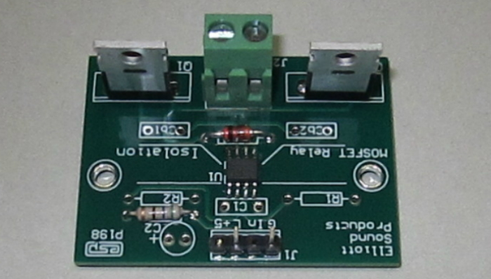
The photo shows a completed P198 board, in this case fitted with ultra-low RDS-on MOSFETs. It's suitable for high power audio switching (RDS-on is about 3.6mΩ for each MOSFET), and with high voltage devices it can handle mains switching easily. It can be used as a lamp dimmer (leading or trailing edge) or small induction motor speed control (leading edge mode only). The IC used in the relay shown is an Si8752, which acts like an LED to the drive circuit. The MOSFETs are selected to suit the application - high voltage (relatively) low current or vice versa. Those shown in Figure 3.3 are an example only.
The only advantage of the next circuit is simplicity, but for most tasks it's fundamentally useless. The 12V supply is required for the optocoupler, which has a maximum rated 30V collector to emitter voltage (with the base open). That means that you can't use the main supply if it's greater than 30V, but you might be able to use a zener regulator to get the +12V supply. If you need a 'real' MOSFET relay for DC, then you're far better off using the Figure 3.1 circuit with one MOSFET. It's polarity sensitive of course, but there are no voltage limits, and it can be on the supply side of the load, something that's harder to do with simplified versions. There are many other possibilities, but they are not 'general purpose' circuits, and are more typically designed into the final circuit.
The benefit of using an isolator such as the Si8752 (or Si8751) is that the MOSFET switch can be used anywhere in the circuit, with the only restrictions on voltage, current and power being imposed by the MOSFET used. While Figure 3.3 does (sort of) qualify as a MOSFET relay, it's really only a switch, and it needs a DC supply to operate. If the +12V supply is floating (referred to the MOSFET's source) then the circuit can be used anywhere you like (high-side or low-side), but providing the extra supply is an added expense and means more parts are used. The diode (D1) is optional, and is necessary if the load is inductive.
MOSFET relays can also be turned on and off with photovoltaic optocoupler ICs - the LED shines onto a bunch of tiny photo-cells which generate enough voltage to turn the MOSFET(s) on. Unfortunately, they are somewhere between slow and incredibly slow, depending on the MOSFET capacitance. Slow switching means high dissipation during the switching period. Some have circuitry to ensure a fast turn-off, but there's nothing you can do to make them turn on quickly (other than use several in parallel). The typical output current is only around 50µA, so with a pair of MOSFETs, it may take up to 5ms for them to turn on because the gate capacitance has to be charged to the threshold voltage before anything useful happens. This might be fast enough for some applications. but it's way too slow for others.
An example of a photo-voltaic optocoupler is the Toshiba TLP591B, but there are many others. All have similar limitations, and they're not inexpensive (around AU$5.00 each). It's sometimes possible to use a small switchmode power supply to provide power, that can then be controlled using a standard phototransistor optocoupler, but this is expensive and bulky. If you need a fully isolated MOSFET relay, it's hard to find anything that will beat the Project 198 circuit. It can be used with AC or DC as shown, but for DC it only needs one MOSFET (the other position is shorted between drain and source).

Photovoltaic optocouplers are fairly common, but MOSFETs with a high gate-source capacitance mean longer turn-on times, and this can be a limitation in many applications. The VOM1271 has an internal 'turn-off' circuit, so at least dissipation is minimised when the SSR turns off. The VOM1271's output voltage is only 8.9V with 30mA LED current, with a short-circuit current of 47µA. For a pair of MOSFETs with a combined input capacitance of 8.4nF (a pair of IRFP460 MOSFETs as shown), it can take up to 6ms to reach full conduction, depending on the load current and supply voltage. The total input capacitance is the gate to source plus Miller (drain to gate) capacitance, and the latter can create 'interesting' effects.
In particular, device dissipation can be very high during the critical turn-on period, although it usually only lasts for a few milliseconds. Unlike the Si8751/2 ICs, there is no miller clamp circuitry to prevent the MOSFET(s) from turning on when the supply voltage is applied with a fast risetime. The MOSFET Relays article describes the circuitry to make a discrete Miller clamp if it proves necessary. The article also shows how to make a turn-off circuit, using a 2.2MΩ resistor and a JFET.
You'll notice that a 12V zener diode is included in all MOSFET and IGBT circuits. This is included to protect the gate's insulation, which is easily damaged by an over-voltage, however it may be caused. It's cheap insurance, and I don't recommend leaving it out of the circuit.
You can also get integrated MOSFET relays, usually in a six or eight-pin package. An example is the LCA110, rated for 350V at up to 100mA RMS or 200mA DC, and there are many similar devices. This type of IC almost always uses a photovoltaic optocoupler, and turn-on/ turn-off times are rather leisurely - 3ms is quoted for 5mA LED current. The TLP592A(F) is another, rated for 60V AC/ DC, and 500mA RMS or 1A DC. Turn-on time is quoted as 2ms (max) and turn-off is 500µs (max). There are numerous similar devices, with many using circuitry similar to that shown in Figure 3.4 (but usually without the 'turn-off' circuit). I expect that a zener is included internally, but its not mentioned in the datasheets.
As of August 2022, TI (Texas Instruments) has advance information available for a new IC, the TPSI3050-Q1 [ 9, 10 ]. This is a magnetically-coupled gate driver that rivals the Si8751/2 devices, but with higher output current. Unfortunately, it's not available from any of the major distributors, so I'm unable to provide any test results. The datasheet is detailed (to put it mildly) and it extends to 40 pages. The IC can be configured in a number of ways, and it's very flexible. An example circuit is shown next, configured for '2-wire' input mode, which offers the simplest configuration.

The isolation is magnetic, using silicon-dioxide insulation which is said to offer a dielectric strength of ~500V RMS/ µm. The internal structure includes a driver stage that can both source and sink current (to/ from the MOSFET gates), so it doesn't need the Miller clamps shown for the Si875x IC. There's a great deal of detail in the datasheet, but a complete circuit (with 'typical' component values) isn't provided. The values shown above are largely estimates, and a MOSFET gate resistor has not been included (a gate drive network is shown in the datasheet, but isn't included in the evaluation module).
The amount of power consumed (and delivered to the MOSFET gates) is determined by the PXFR pin and associated resistor. There are seven power levels available, and I selected the 'mid-range' value in Fig. 3.1.1. The power level is increased as RXFR is increased, with maximum power delivered with 20k. While I've shown the circuit in '2-wire' mode, you can get faster switching using the '3-wire' configuration. This requires a separate 5V supply connected to VDPP. Current consumption can be up to 37.56mA (RXFR = 20k).
The datasheet for the TPSI3050-Q1 does no-one any real favours. Everything you need to know is there, but it's 'distributed' throughout the datasheet in a way that makes it very hard to read. A couple of 'reference' designs would have been very useful. The evaluation board is (allegedly) available, and the datasheet for that is more concise (18 pages). It includes the schematic and provides some useful information.
Most SSRs are normally open, and require a signal to turn on. This is very unlike EMRs, which can provide both normally open (NO) and normally closed (NC) operation, including changeover types. It is possible to use depletion mode MOSFETs, but they are far less readily available than enhancement mode types, and have a limited range of voltage and current ratings. Most are also far more expensive for similar ratings, so normally closed SSRs are uncommon. This is a nuisance, because normally closed relays are used in many applications.
The equivalent is to use a standard MOSFET, IGBT, SCR or TRIAC SSR that normally has power, so is turned on by default. To turn it off means removing the drive signal. If a pair of SSRs are used to provide a changeover function (SPDT - single-pole, double-throw in EMR parlance), you must ensure that there's an in-built delay. Because switching can be almost instantaneous, any overlap (where both relays are partially on) could cause serious circuit malfunction. This is especially true with TRIAC and SCR types used with AC, because the set that's conducting will continue to do so until the current falls to zero. This may require a delay of up to 10ms to ensure that the conducting SSR has actually turned off. If you need this functionality, a supervisory circuit would be advisable to lock out the non-conducting SSR until the other has completely ceased conduction.
While IGBTs may seem ideal for relays, they can have some disadvantages compared to MOSFETs. It may seem that a disadvantage is speed - MOSFETs are much faster than IGBTs, but for relays this is rarely a major consideration. One of their benefits is that they are available with very high voltage ratings (up to 2,500V), and often (but not always) have a lower voltage drop at maximum current. A couple of examples are shown below, selected for the same voltage, current and similar power ratings only. Each MOSFET will dissipate 103W at 30A, while the IGBTs will only dissipate 55.5W. However, note that the dissipation limit is at 25°C, and the datasheet will show the derating factor for elevated temperatures. Like a MOSFET where an increase of temperature increases RDS-on, the voltage drop across an IGBT (VCE-sat) also rises with increasing temperature. However, this is only an issue with very high current - at low current (e.g. 5A through a 30A IGBT) it will typically remain fairly constant.
Technology Type No. Ratings V Drop @ 30A Cost (2020)
MOSFET R6030ENZ4C13 30A, 600V, 305W 3.45V (104W) AU$7.80 IGBT STGW30V60F 30A, 600V, 260W 1.85V (56W) AU$6.19
Those shown above are examples only, and do not include the dissipation of the reverse diode. You can get IGBTs that can handle transient currents up to 570A, and voltages up to 2.5kV (not in the same device though!). Although you will see specifications that seem quite impossible, they are almost always 'short-term', typically for no more than 1ms or so. All semiconductors are ultimately limited by allowable power dissipation vs. temperature, and any time you need to switch significant current you're going to need a heatsink. Adding a large aluminium heatsink (likely with a fan to provide the best cooling possible) does nothing for the apparent size reduction compared to a large EMR or contactor.
There appear to be very few IGBT relays available. There don't seem to be any reasons that you can't use the Project 198 board with IGBTs (although I've not tested this), but it can't switch audio, and for AC applications the IGBTs must have 'anti-parallel' (aka freewheeling) diodes. Some do, some don't. Without them, the IGBTs will almost certainly be destroyed with AC applied. While using IGBTs may provide some benefits for certain applications, most of the time P198 will use MOSFETs as designed.
The IGBTs shown (NGTB15N60S1EG) are an example only, in this case selected for the in-built anti-parallel diode rather than any specific characteristics. The PCB wasn't designed for the kind of current those devices can handle (30A), but it's an inexpensive device (AU$2.20 in 2020) and probably would serve well for mains switching. The saturation voltage is 1.75V (typical) so it would dissipate 17.5W at 10A (this does not include the diodes, so total dissipation will be closer to double (~35W each). This is expected for IGBTs in general. Note that a TRIAC SSR will dissipate around 10-15W at the same current.
The same arrangement can be used for DC of course, and only one IGBT is needed. If the P198 PCB is used, the other device position is simply shorted between collector and emitter (equivalent to drain and source for a MOSFET).
TRIAC SSRs are (almost literally) as common as dirt. They've been around for many years, and are available as complete modules. With current ratings from 200mA up to 70A, there's a TRIAC to suit your requirements. However, be very careful when ordering modules or driver ICs, as they come in two distinct 'flavours'. Zero voltage switching (ZVS, aka ZV or ZC - zero voltage/ crossing) types are very common, and often the part number doesn't indicate that the relay uses ZV or 'random' switching. Despite what you might think, transformers and motors should never be turned on using a ZVS TRIAC (or SCR) relay. Doing so guarantees the maximum possible (worst case) inrush current ... every time it's turned on!
This is documented (with waveforms) in the Transformers articles, and I used a purpose-designed switching system that allows the voltage to be switched on at the zero crossing or the peak of the AC waveform. For minimum inrush current, power should be applied at the peak AC voltage (nominally 325V for 230V mains). It would be helpful if a peak voltage switching TRIAC/ SCR relay were readily available, but as near as I can tell they are only available from industrial specialist suppliers, and they are very coy about disclosing details. So-called 'random' switching TRIAC relays can be turned on at any time during the cycle, other than at the zero-voltage crossing because there's no trigger voltage (or current) available.
What exactly is a TRIAC? They are described as a subset of the thyristor (SCR) series of devices, and are effectively a pair of SCRs back-to-back (with a modified gate topology). An SCR is the solid-state equivalent of the original gas thyratron [ 1 ] (a switching valve). These look like (but are not) vacuum tubes, because they use gas internally. The term 'thyristor' is a combination of 'thyratron' and 'transistor', and SCRs became commercially available in 1958. A TRIAC is a bidirectional version of the basic thyristor (the name comes from 'TRI' meaning three [terminals] and AC - alternating current), and can switch AC with a single device (two SCRs are needed for AC switching). The SCR and TRIAC were pioneered by General Electric [ 4 ]. While TRIACs seem to be simple enough in principle, there are many considerations for reliable operation.
The turn-on characteristic of a TRIAC (and an SCR) is regenerative - as current is drawn it causes the device to turn on faster, resulting in very rapid voltage and current transitions. If the voltage across the device is high, the turn-on speed (and harmonic amplitude) is such that it can create electrical noise into the MHz regions, and many circuits that use TRIACs (e.g. leading-edge light dimmers) require RF filtering to reduce the electrical noise. Regeneration is just another word for positive feedback.
One of the lesser known aspects of TRIACs is that they are sensitive to polarity. In theory, it doesn't matter if the trigger signal is positive or negative, regardless of the polarity of the incoming waveform, however this isn't strictly true. The above drawing shows the four possible quadrants for conduction, and quadrant IV is troublesome. If the main terminal 2 (MT2) polarity is negative, a positive gate voltage will turn the TRIAC on, but it is insensitive compared to quadrants I-III. It's worth noting that some TRIACs are specifically designed to exclude Q4 triggering. These are often referred to as 'Snubberless™ ' TRIACs, because by excluding Q4 triggering, many of the problems associated with this triggering mode are eliminated. You may also see them referred to as an 'Alternistor™' or High-Commutation (Hi-Com™) TRIAC, depending on the manufacturer. Quadrants I and III are optimum, but not always achievable.
You will also see the main terminals of TRIACs referred to as 'A1' and 'A2', equivalent to MT1 and MT2 (Main Terminal 1, Main Terminal 2). The 'A' designator means 'anode', which can be misleading, as it's debatable whether these terminals are anodes or cathodes. Nevertheless, if you see a TRIAC indicated with A1 and A2, these are equivalent to MT1 and MT2, with the gate referred to A1 or MT1.
 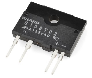 |
Figure 5.1 shows a simplified drawing of a commercial TRIAC SSR, along with a photo of an example. The one shown is only relatively low current (400V peak at 8A maximum, zero volt switching), and it's designed to be used with a heatsink if operated at maximum current. The photo-TRIAC is internal, but there are many trigger ICs available from a number of vendors. The MOC3022 (and its ilk) are probably the best known, and they can be used by themselves for low-current applications. They can be used with a current up to 100mA, but lower current is preferable to prevent overheating (50mA at 70°C). Versions are also available that include ZVS logic. They are sometimes referred to as 'ZC' and 'NZC' - zero-crossing and non-zero-crossing.
The optocoupler is powered via a current source (Q1, Q2, R3) that keeps the current through the opto constant over the full input voltage range (5-20V DC). The current regulator that ensures that the optocoupler gets the same current whenever the control voltage is present, regardless of voltage (within reason). With R3 at 56Ω the current is about 12mA. The indicator doesn't have a current limiter, but one can be included if desired (or you can omit the indicator). The current regulator isn't needed if the control voltage is fixed - you only need to use a series resistor to keep the opto's current between 10-15mA. Q1/ Q2 can be any small signal NPN transistor you have to hand - it's not critical. Worst case dissipation is less than 170mW at 15V input. The snubber and MOV are optional, and are only required if you have an inductive load and/ or noisy mains.
The schematic includes circuitry intended to handle inductive loads, and it's been simplified by using the same value resistors in all trigger locations. These may require adjustment with troublesome loads. In some cases these can cause serious misbehaviour, so the extra RC networks act as snubbers to limit the DV/Dt applied to the TRIAC and trigger IC. The second snubber (C2, R7) may be subjected to extremely fast transitions, so both the resistor and capacitor need to be pulse-rated types. The worst case current in this network is around 1.2A peak with 230V mains, so the peak dissipation in R7 may be up to 70W. It's very short-lived, but you'd need to use a carbon composition resistor. These resistors are designed for pulse applications.
Dedicated R/C networks are available for this, providing both parts in a single component. The example shown uses a metallised paper capacitor and the device can handle 12A pulse current. Discrete (pulse rated) parts can also be used. Don't imagine that you can use X2 or even X1 capacitors, as they are metallised film types, they are not pulse rated and will fail. Only capacitors specifically designed for high-current pulse applications will survive. The peak current through the snubber depends on the AC voltage and where it's switched, but worst case is up to several amps, resulting in extremely high instantaneous dissipation. With 230V mains, the peak dissipation may be 120W with a 47Ω resistor. The average dissipation is low - usually a few milliwatts. The capacitor also needs to be able to handle the same peak current, so will use foil rather than metallised film.
If one is building a home-made TRIAC SSR that will behave itself with any load, I suggest that snubberless TRIACs be used. An example is the BTA26-800CWRG, a 25A, 800V 3-quadrant TRIAC. There are many others of course, and most of the time you don't need to be to picky. The disadvantage of 'standard' TRIACs is that the snubber is usually necessary if the load is inductive. The use of a MOV (metal oxide varistor) is optional, and not necessary in most cases.
TRIACs (and SCRs, covered next) have a minimum current requirement (called 'holding current'), below which they will turn off. This can range from a few milliamps to 500mA for high-current types. If your load doesn't draw enough current, a TRIAC may fail to reach the latching current and it won't stay on after the trigger pulse has ended. Either situation may cause a TRIAC (or SCR) relay cease conduction unexpectedly. They also have a maximum voltage rate-of-change (called DV/Dt or ΔVΔt, aka Critical rate of rise of off-state voltage), and if the applied voltage rises faster than the maximum allowable, the TRIAC will conduct. It's common to use a snubber (resistor-capacitor) network in parallel with the TRIAC to limit the DV/Dt and prevent spontaneous conduction. You also need to be aware of the critical rise of on-state current (DI/Dt/ ΔI/Δt). If this is exceeded the TRIAC may fail due to internal 'hot-spots'.
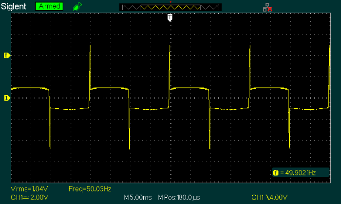
These devices are inherently somewhat electrically noisy. The leading-edge spikes visible on the waveform indicate very fast transitions, which means there must be high-frequency electrical noise. These spikes are narrow, (about 100µs, but with very fast transitions as the TRIAC conducts), ensuring that the frequencies generated extend to several MHz. The waveform shown was obtained from a FOTEK SSR-25-DA TRIAC SSR. This is a ZVS type, rated for 25A at up to 380V AC. The waveform was obtained with 40V AC and an 8Ω load - 5A RMS. As expected, the forward voltage is 1V, and it changes very little with current. Dissipation is 1W/A, so it dissipated 5W during my test.
The spikes at the beginning of each half-cycle show that a specific voltage must be present (at least 5V peak) to allow the TRIAC to latch, in this case providing around 625mA. Low voltage tests showed that with less than 5V RMS the Fotek SSR either won't turn on at all, or misbehaves (½ wave operation). Using it for a low voltage or low current load won't work, and it ceased 'normal' conduction with anything under 100mA load current. This is quite unlike an EMR, which will normally function happily at almost any voltage or current within its ratings.
TRIACs should never be operated with any load that draws less than the worst-case latching current (if you're brave enough, you can use the 'typical' value instead). For the BT139 series, the maximum is 40mA, but I wouldn't be entirely happy with that. You're much safer by doubling the worst-case figure, especially with difficult loads (reactive or electronic loads for example). This means around 20VA with 230V mains or 10VA at 120V. There's every chance that it will work at less, but conduction may be erratic with some loads.
Despite these warnings, most TRIAC SSRs (or just TRIACs) will switch power transformers without problems, and a few manufacturers have used a TRIAC so the mains switch can be a low current type. It still needs to be rated for the full mains voltage, but the tiny TRIAC gate current means there's no need for a heavy-duty switch to turn the equipment on or off. It's mot (strictly speaking) a relay, because there's no isolation, but it still allows a large current to be controlled by a much smaller current.
In the above, the switch only needs to handle a few milliamps, while the TRIAC may be used to switch a very large power transformer. This would normally require a heavy-duty switch, but for aesthetics many designers would rather use a miniature switch. It still has to be rated for mains voltage, but the dramatic reduction in current means that even a light-duty switch will probably outlast the equipment. The TRIAC may require a heatsink if sustained high current is drawn (1W/ Amp is typical for most TRIACs). R2 and the snubber network are optional, and may (or may not) be needed in the design.
With a BT139F-600 TRIAC as shown, anything above an average current of 1A will require a heatsink (remember, TRIACs dissipate 1W/A). The 'F' suffix means it's a 'full-pack' (fully isolated) package, so mica washers and insulating bushes aren't needed (and are a very bad idea if you're isolating mains voltage). You must use thermal compound between the TRIAC and the heatsink. Care is needed to ensure that the TRIAC leads have appropriate creepage and clearance distances so they cannot short to the heatsink, which will often be the chassis if it's made from aluminium. The installation must have a cover to prevent accidental contact, and the wiring to the switch must use mains rated cable.
In most respects, SCR (silicon controlled rectifier) SSRs are similar to TRIAC types, and the same photo-TRIAC optocouplers can be used to drive them. There are benefits to using SCRs rather than TRIACs, particularly in terms of current capacity. For example, the CLA50E1200HB thyristor is rated for 1200V, 50A, and a power dissipation of 500W, in a familiar TO247 plastic package. At under AU$10 each (2020 price), a pair can handle a prodigious load. With a peak current rating of 650A (10ms), it can handle far more current than any household outlet can supply. The trigger current is 50mA (max) at 25°C.
The following drawing shows an SSR with a pair of SCRs. This drawing is very similar the one shown above (Figure 5.3), but modified to use SCRs. An SCR SSR is somewhat less susceptible to spurious or spontaneous conduction, so trigger snubber networks should not be necessary. SCRs are available with much higher current ratings than TRIACs (the latter are limited to around 40A), while SCRs can handle 2,000A or more (somewhat outside the range of DIY circuits). Voltage ratings are also much higher, at up to 2.6kV - they are not generally affordable for DIY, and require more sophisticated trigger networks. Predictably, these are not covered here, but it gives you an idea of the range available.
In the above drawing, I used SCRs that are a little more in line with those that might be used in a DIY version. They can still handle 20A RMS for the pair, and can provide a peak current of 200A for 10ms. One of the biggest advantages of using SCRs rather than a TRIAC is that the power is shared by two devices, so it's easier to keep them cool due to the effective halving of the thermal resistances. The current regulator is the same as that used for Figure 5.3. As with the TRIAC version, the snubber and MOV are optional, and are only required if you have an inductive load and/ or noisy mains.
SCRs have a PNPN semiconductor arrangement, with an additional doped section to create the gate. It's remarkably easy to make an SCR using a pair of transistors. The concept is shown below, and it works just like the 'real thing' except that the current is limited because much of it must pass through the base junctions. The 'on' time is extremely fast, because the two transistors operate in a positive feedback loop. According to the simulator, conduction starts within 15ns of the applied trigger pulse, and the load current risetime is under 18ns.

While the circuit is impractical for power circuits, it's worth remembering if you ever need a low current, highly sensitive latching switch. Like all SCRs, it has a minimum holding current. In this case, it's about 65µA, set by R1 and R2. However, expecting it to function with less than 5mA is probably unwise. With any current between 7mA and 50mA, the voltage across the 'SCR' remains at around 800mV. This depends on the transistors used (I used BD139 [NPN] and BD140 [PNP] for the simulation). The diode prevents the 'gate' resistor de-sensitising the circuit (and increasing the required holding current). Unlike a 'real' SCR, the transistor version can be turned off. GTO (gate turn-off) thyristors are available, but it takes a high-energy negative gate pulse to do so.
It's important to understand that SCR relays (along with TRIACs) have some leakage current, which is specified in the datasheet. If an R/C snubber network is included in parallel with the relay, this is increased, based on the capacitance and frequency. For example, a 10nF capacitor will pass 722µA at 50Hz, and this may be more than you'll get due to reverse 'off' leakage. The BT152 series SCRs have a maximum leakage specification of 1mA at 125°C and at maximum rated voltage. This is usually ignored, but it means that there is some risk of a 'tingle' if you rely on an SCR relay to isolate mains voltages. This is one reason not to use them as a safety cutout.
A single SCR can also switch AC by using it between the +ve and -ve terminals of a bridge rectifier, with one AC terminal as the input and the other as output. High current SCRs are cheaper and have lower power dissipation than high-current bridge rectifiers, so it not a useful technique and isn't shown here.
In the descriptions above, zero-crossing, random and peak switching were mentioned. MOSFET (and IGBT) relays are always 'random' unless additional circuitry is included. Zero crossing detectors are discussed in detail in the AN-005 - Zero-Crossing Detectors article, and similar circuitry is incorporated into ZCS TRIAC driver ICs. Obviously, you can't turn on a TRIAC or SCR when the voltage is actually zero, and most have a threshold of up to 35V before triggering occurs. This only works properly when the AC supply voltage is above 30V RMS, because at lower voltages it may not be able to trigger at all.
Peak switching is somewhat harder. While it's certainly possible to capture (and hold) the peak voltage, this takes time. Typically, it may take up to 40ms (two complete cycles at 50Hz) before the circuitry can detect the peak voltage and trigger the relay. The alternative (and the method I used for a dedicated inrush current tester I made) is to detect the zero-crossing, and wait for 5ms (90° shift at 50Hz, which is the peak voltage) before triggering the TRIAC or SCR relay. This isn't hard to do, but it does involve additional circuitry. Different units would be needed for 50Hz and 60Hz applications, so it's no great surprise that this method won't be used in commercial devices.
Random switching means that the SSR will turn on as soon as there's enough voltage present to cause a TRIAC or SCR to trigger and latch. With MOSFET or IGBT relays, they will turn on when gate voltage is above the threshold - even with zero current - so there is very little delay. With most random switched TRIAC/ SCR relays, the worst case delay will only be a couple of milliseconds in most cases.
The trigger signal for TRIAC/ SCR relays can be continuous or pulsed at a high frequency (usually > 10kHz). The latter system is common when triggering is applied using pulse transformers. This approach has not been covered here, but an example is shown below. Pulse transformers have some advantages over optocouplers, in that they can offer higher triggering current, and are not subject to DV/Dt limitations to the same extent as TRIACs. Pulse switching can be configured for zero-crossing, peak, random, or a specific phase angle (used for dimmer circuits). The drive circuitry is more complex than using optocouplers.
While this approach looks ideal, the pulse polarity is important. Refer to the triggering quadrants shown in Figure 5.1, and it's apparent that quadrants II and III are the only option (since quadrant IV should be avoided with many TRIACs [ 5, 6 ]). This means that the trigger pulses should be negative, although it's a moot point when a transformer is used because the DC reference is always the average value of the waveform.
Including the Schottky diodes forces the majority of the pulse voltage to be negative, enabling triggering in quadrants II and III. This avoids quadrant IV altogether, and will usually give the best performance. If the trigger pulse frequency is high enough the diode can be omitted, so even if the TRIAC attempts (but fails) to trigger in Q4, it's only a few microseconds before the polarity reverses so it will trigger properly. When using pulse triggering, the pulse train is required for as long as the TRIAC is turned on. Applying only a single pulse at the point where conduction is required may cause operation to be intermittent, especially with inductive loads.
The worst possible fault occurs when the TRIAC only conducts half-wave, as that can burn out a motor or transformer. This is not at all uncommon, especially if the designer attempts to trigger in quadrant IV. Unfortunately, it seem that most hobbyists (and even patent applicants) are unaware of the 'quadrant IV problem' with TRIACs, and try to trigger using only positive pulses, when negative pulses will always work better. If you check TRIAC datasheets, you'll find that quadrants I-III are more sensitive than quadrant IV (the latter may require up to double the trigger current of quadrants I-III), and many TRIAC types disallow quadrant IV triggering altogether.
The pulse transformer must be rated for the isolation voltage needed for the circuit, and will typically be at least 2kV. These are readily available from many suppliers. A snubber has not been included, but may be required depending on the application.
If you're willing to add an auxiliary power supply, the realisation of a MOSFET SSR can be 'simplified'. There are numerous small isolated DC-DC converters available, and the smallest (typically 1W) are more than sufficient to drive MOSFETs. The ideal is a 12V-12V converter, and these are usually rated for up to 100V isolation or more. There are two ratings - one is for the isolation test voltage (~1kV) and the other for working voltage. In some cases, much higher isolation voltages may be available. These devices are small, usually no more than 20 × 6 × 10mm (L, W, H) in a single-inline package.

Suitable devices will have an input voltage range of around 10.8-13.2V and an output voltage of 12V. A 1W converter can supply 84mA, and an output capacitor can ensure that even MOSFETs with a high gate capacitance can be turned on quickly. The control device will usually be a standard optocoupler (LED + transistor), which is easily driven from the control circuitry. The circuit shown above is an example only, and there are many other options.
The scheme shown is deliberately 'minimalistic', and it's not difficult to improve it. However, this inevitably means more parts, expense and PCB real estate. The optocoupler is always a compromise, because they have widely differing CTRs. With a CTR of 100%, 10mA into the LED will result in up to 10mA through the transistor. The LTV817 is only a suggestion, and there are many others that will be suitable. The value of R2 ensures that the MOSFET gate capacitances discharge fairly quickly, without demanding too much current through U2.
When any LED based optocoupler is used, lumen depreciation must be considered. Some manufacturers provide a graph for this, but most don't. Over time, the LED's output will fall, reducing the CTR. If you fail to make allowances, the circuit may cease to provide enough output voltage to ensure that the MOSFETs are fully conducting. As shown, the phototransistor current is only 1.2mA, so there is plenty of leeway for a device with a CTR of 100%, and still some reserve for a CTR of only 50%.
There is a huge variety of different types of relay (EMR and SSR), not just for switching devices but for input requirements as well. Some SSRs are designed exclusively for use with AC, others are exclusively DC. A small number of commercial SSRs can be used with AC or DC. In this respect they are far more restrictive than EMRs, but they also offer some unique advantages. Needless to say, they also come with some unique disadvantages as well.
SSRs can use a wide variety of isolation and control techniques, including reed relays (which strictly speaking makes it a hybrid), AC/DC or DC/DC converters, mains frequency transformers, high-frequency pulse transformers, or (and most commonly) infra-red light within an IC package. Optocouplers outnumber the other techniques by a wide margin for medium power devices. If significant power is being controlled, the control circuitry will probably use a pulse transformer.
Like conventional relays, most SSRs provide galvanic isolation between input and output, commonly rated for 2-3kV as a matter of course. Rather than using a coil to operate the relay, SSRs generally use an optocoupler (the Si875x is a notable exception), so the activating medium is infra-red light rather than a magnetic field. Where an electro-mechanical relay may require an input power of up to a couple of Watts (down to as little as 100mW), SSRs generally function with as little as 50mW, with some needing even less.
However, where the contacts of a conventional relay may dissipate only a few milliwatts, an SSR will usually dissipate a great deal more, with high power types needing a heatsink to keep the electronic switching device(s) cool. This is because the switching element is a semiconductor device, and therefore is subject to all the limitations of any semiconductor. This includes the natural enemy of all semiconductors - heat! Common switching devices are SCRs, TRIACs, MOSFETs and IGBTs, and each has its own specific benefits and limitations.
Be particularly careful if your application has a high inrush current. The worst case maximum current must be within the ratings of the SSR, or you run a very real risk of destroying your relay. SSRs have a bewildering array of specifications (some are more inscrutable than others), but the maximum allowable current will always be specified (typically as the 'non-repetitive peak surge' current). Note the use of the term 'non-repetitive' - that means whatever the maker says it means. It might be for 20ms (one cycle at 50Hz), it may also mean for some other specified duration (e.g. 1ms), and if you are lucky there will be a graph and even some info on how to deal with inrush current. For more information on this topic, please read the Inrush Current article.
Switching Used For Comments
SCR ½ Wave AC Two are commonly used in reverse-parallel for high-power full-wave AC TRIAC Full Wave AC Generally only used for low power versions (10A or less for example) MOSFET AC or DC AC and DC versions are available, but are generally not interchangeable IGBT AC or DC As above, but not suitable for audio. Suitable for high current/ voltage
To look at some of the many techniques used for MOSFET relays, see the article MOSFET Relays which describes the various drive circuits that can be used. The article is primarily aimed at loudspeaker DC protection circuits, but similar techniques can be used elsewhere. DC MOSFET based SSRs may simply use a MOSFET and a photovoltaic opto-coupler. There is generally little or no advantage to using the pre-packaged version over a discrete component equivalent, except in cases where the certification of the SSR is needed for safety critical applications. While this is possible, EMRs are usually preferred because there is zero leakage when they're turned off.
The general arrangement shown in the schematic of Figure 5.2 is common to most SCR and TRIAC based SSRs. The optocoupler can be purchased as a discrete IC in either 'instantaneous/ random' or 'zero-crossing' versions. In this case, 'instantaneous' (or NZC - non-zero-crossing) simply means that the opto-TRIAC will trigger instantly when DC is supplied to the LED, regardless of the AC voltage or polarity at that moment in time. The zero-crossing versions will prevent triggering unless the AC voltage is within (typically) 30V from zero. Examples are the MOC3052 (instantaneous/ random phase) or MOC3042 (zero crossing). Both are rated for 10mA input current.
You also need to carefully read through the documentation to make sure that your supply and load can never exceed any of the limits described in the datasheets. A momentary over-voltage generally won't cause the contacts of a standard relay the slightest pain, and even short-term excess current is usually not a problem. With a solid state relay, no limiting value can be exceeded ... ever. You also have to ensure that the voltage and/or current don't change too fast, because SCRs and TRIACs have defined limits, known as DV/Dt (critical change of voltage over time) and DI/Dt (critical change of current over time). If either is exceeded, the device may turn on unexpectedly or be damaged. You will also see these terms written as ΔV/Δt and ΔI/Δt.
The maximum peak voltage can't be exceeded either, and woe betide you if the load draws more than the rated peak current. You also have to use a heatsink if the load current would otherwise cause the temperature to rise above the rated maximum (typical absolute maximum junction temperature is between 150-175°C). There are many disadvantages, but sometimes there is no choice. For example, you can't use a mechanical relay in a 'phase-cut' dimmer because it can't act quickly enough. You also can't ensure that a mechanical relay switches on at a particular phase angle of the AC waveform - for example, the ideal for an inductive load is to apply power at the peak of the AC waveform. This is easily done with an SSR.
Although rarely specified as such, TRIAC and SCR SSRs have a minimum current rating, below which erratic operation is likely. If the load current is below the latching current required, the SSR will either not conduct properly (e.g. ½ wave operation), or it may not conduct at all. This is usually not an issue with EMRs, although some do specify a minimum current to ensure the contacts don't remain open due to surface contamination. This usually only occurs with very low voltages.
It's worth another look at the (generalised) advantages and disadvantages of semiconductor compared to electro-mechanical relays.
SSR Advantages ...
SSR Disadvantages ...
The inability of most SSRs to provide changeover contacts or multiple sets of contacts can be a serious limitation, and can also increase costs significantly. It costs very little to add another set of contacts to an electro-mechanical relay, but with the SSR you need an extra high current switching device, and an improved driver to suit. In most cases if you need a circuit to be normally closed with power off then you're probably out of luck. Such things do exist (using depletion-mode MOSFETs), but I've never come across one other than in datasheets.
One area where MOSFET and IGBT based SSRs excel is interrupting high voltage, high current DC, which is fundamentally evil. At voltages over around 35V and with enough current available through the circuit, DC will simply arc across the contacts of most mechanical relays and switches. With high current, the arc will melt the contacts and contact arms until the air gap is finally big enough to break the arc. Think in terms of an arc welder, because that's the sort of conditions that can exist with enough voltage and current. A MOSFET doesn't have that limitation, and can break any voltage or current that's within its ratings.
There are also many small (DIP6, DIP8 or SMT) MOSFET relays available. These are not suitable for high current, but some are likely to be a good choice for switching audio and other low-level signals. Voltage ratings range from around 60V up to 300V or more. Example include the G3VM-61G1 (60V, 400mA AC), LH1156AT (300V, 200mA AC) and PVDZ172N (60V, 1.5A, DC). These are chosen more or less at random, and there are hundreds of different types. As expected, all those I've seen are SPST normally open. Operating principles are much the same as described above, but everything is in a single package. For AC/DC types the voltage rating is the peak AC or continuous DC voltage.
Solid state relays should never be used as a safety-critical shut-off system. Because failure commonly means a shorted switching device, should the SSR fail the load will be permanently energised. You must know your load characteristics, and be aware that many SSRs may not turn off if the load has a characteristic that generates transients fast enough to cause spontaneous re-triggering of the SCR or TRIAC. Some non-linear loads may cause the SSR to trigger on only one polarity, causing half-wave rectification and a net DC component in the load's supply circuit (typically the mains). Some SSR problems (even if transient) can cause serious malfunctions in other equipment that shares the same power source. For example, transient half-wave rectification of the mains may cause transformer saturation, serious motor overload (saturation again), tripped circuit breakers and general havoc.
With any SSR, never underestimate how hot the switching device(s) may get. For a TRIAC, 1W/A may not sound like much, but even a large stud-mount package will get very warm dissipating only a couple of watts (2A), and smaller packages are worse. The switching devices may be inside a chassis with little or no cooling, making the problem more critical. Proper testing is always necessary, something you usually don't have to worry about with EMRs. Likewise, don't assume anything else - SSRs can (and do) misbehave with some loads, they use semiconductors that fail short-circuit, and they can be 'accidentally' turned on with a momentary voltage spike.
Whether (or not) this is a problem depends on the application, and whether the device fails (or not) as a result. For mains applications, consider using a MOV (metal oxide varistor) to limit the peak voltage. For 230V applications, don't use anything less than a 275V RMS rated MOV (or around 400V peak). For 120V, use a 150V RMS MOV 220V peak). These devices are somewhat 'rubbery' in their specifications, and may have a negative resistance characteristic when they conduct. When used to clamp very high-energy, it's not uncommon for them to fail catastrophically, so don't put anything delicate near them.
MOVs are a topic unto themselves, so I recommend that if you wish to include one, you read as much as you can, and only buy from recognised suppliers. Littelfuse makes a device they call a TMOV, which includes an internal thermal switch. This prevents the MOV from scattering itself throughout the chassis if it fails, but of course if the thermal fuse fails, the MOV is permanently out of circuit (and you won't know that it's happened). At least if you hear an explosion inside your gear you know something has failed, but that's not something most people want to experience.
Snubbers are a pain, so wherever possible use 'Snubberless' TRIACs, which (by definition) don't need them. Adding a snubber means that more PCB real estate is used, and while they aren't especially expensive, every extra part adds to the size and cost. In some cases (with TRIACs and SCRs), it may be necessary to include a small inductance in series with the load. This limits the ΔV/Δt applied to the switch, and helps to reduce the ΔI/Δt as it turns on.
MOSFET SSRs have their own limitations, but with a judicious MOSFET selection there should be few problems. Very high switching speeds are not achieved when using a driver IC such as the Si8752, so EMI is rarely an issue. It's still essential to perform proper testing to ensure that the MOSFETs never get more than slightly warm in normal use, and a heatsink may be needed if you have to carry a high continuous current. Low RDS-on minimises the dissipation, but it's always non-zero when current is being carried.
Mains safety is always important. Any SSR used for switching mains voltages should be protected from accidental contact. All connections need to be secure so that nothing can become detached leading to short circuits or other hazards. Never wire mains circuitry using Veroboard or similar, because the tracks are too close together and they don't have acceptable creepage or clearance distances. Tag strips, blank PCB material with hard wiring or a properly designed PCB are needed to ensure electrical safety. Never use mica insulators and mounting bushes to mount a TRIAC to a heatsink, as they do not provide acceptable creepage and clearance distances. Remember that all mains wiring must use mains-rated cable, not 'general purpose' hook-up wire.
There is no doubt that some applications demand the use of an SSR. For example, switching off a 100V DC supply with a load current of 20A is almost impossible with anything else. However, they have drawbacks as well, most notably in price and thermal limitations. Sometimes it's worth looking at a hybrid system (see Hybrid Relays for info), or even investigating active arc suppression techniques (see Arc Mitigation & Suppression). Ultimately, what you do will be a compromise, but if you can get all your information together and work out a solution, you can get the best performance for the least cost. You will pay for it in terms of complexity, but if it's the only sensible way to make something work reliably, then that's the price that must be paid.
When I publish projects, I make it a habit to always test any hypothesis that presents itself. The same applies to articles, as there's no point disseminating information that's not demonstrably accurate. Many tests are done using a simulator, but anything 'interesting' gets bench tested as well. Unfortunately, the Interweb has given a voice to anyone who can type (particularly in forum pages), and there's a vast amount of misinformation available. Beginners usually don't know any better, and often take completely false information as gospel, where it's promptly re-posted until it becomes so common that people assume it must be true. It wasn't to begin with, and no amount of re-posting a falsehood will make it real.
If you do your homework, study datasheets and run some tests, you'll find a solid-state or electromagnetic relay that will do just what you need. In some cases you'll find that an EMR is still the best choice, and this may apply much of the time for 'normal' switching. In some datasheets and discussions you'll see that much is made of the high sensitivity of SSRs reducing wasted power, but in reality the switching semiconductors will often dissipate far more power than even the most insensitive electro-mechanical relay of similar load ratings. With any SSR, you must do your homework, and be aware of the many things that can go wrong. Also be aware that a fault in an SSR may cause damage to other equipment, even if it's not controlled by the SSR but just happens to be on the same mains feed.
As with everything in electronics, you will have to compromise somewhere. On the whole, conventional relays usually have fewer compromises than solid state versions, and offer far more flexible switching. With a mere half watt input, you can control 2kW or more with ease, and you can expect it to work for hundreds of thousands of operations, even at full load. Switching losses are minimal, no heatsinks are needed, and reliability is outstanding if you use the right relay for the job. Importantly for many people, electro-mechanical relays are far easier to get and usually much cheaper than a solid-state equivalent.
There are also many applications where nothing can beat a solid state relay. Complete freedom from arcing, which is really important in hazardous environments with flammable material, such as gas or fine suspended particles (powders, flour, etc.), fast (MOSFETs), exceptionally fast (SCR and TRIAC types) and predictable response times, and lack of contact bounce can be critical in some designs. The process of design is based on knowing the options that are available so you can choose the one that will work best in your project. There is no 'best' solution for all applications, and it's up to you to choose the solution with the smallest number of entries in the 'disadvantages' column.
Wikipedia isn't the most reliable reference location, but the descriptions for these devices are fairly good.
The ESP articles referred to at the beginning are also very useful, and are possibly the most complete descriptions you'll find in any one place.
| Main Index
Articles Index |
