
|
|
| Elliott Sound Products | Project 157 |
Before I start to describe this project, I must warn any prospective constructor that all circuitry is directly connected to the mains, and you cannot work on or measure any part of the circuit while it's powered. Measurements are difficult, and you cannot use an oscilloscope to measure anything unless you have an isolation transformer. One slip of a meter probe can cause instant destruction of you or the circuit. Dead circuitry can be replaced, but you can't !
| WARNING - The circuits described herein involve mains wiring, and in some jurisdictions it may be illegal to work on or build mains powered equipment unless suitably qualified. Electrical safety is critical, and all wiring must be performed to the standards required in your country. ESP will not be held responsible for any loss or damage howsoever caused by the use or misuse of the material provided in this article. If you are not qualified and/or experienced with electrical mains wiring, then you must not attempt to build the circuit(s) described herein. By continuing and/or building any of the circuits described, you agree that all responsibility for loss, damage (including personal injury or death) is yours alone. Never work on mains equipment while the mains is connected ! |
You might think that the warning is over the top, but it's very important that the reader understands the hazards of household mains and is aware of the consequences of poor workmanship or incorrect materials used for mains wiring. Any work on the circuits described must only be performed when the entire circuit is disconnected from the mains.
This is the very first complete 3-wire trailing edge dimmer project on the Net as far as I know. I have published a circuit by Atmel that does the same thing, but that requires an IC that is not readily available (an Atmel U2102B multi-function timer, now listed as obsolete with no replacement). In contrast, this circuit uses readily available parts throughout, and has been built and tested. 60Hz operation has not been verified by testing (I don't have a 60Hz mains source available), but there's nothing to suggest that the modifications described further below will not work as described.
As shown here, the dimmer is intended for use with 230V/ 50Hz mains, and there are some modifications needed for use at 120V/ 60Hz. The changes needed are described later in the article. The differences are based on the timing, power supply and the zero crossing detector, all of which must be changed to get the unit to work properly at 60Hz and 120V.
Note that the dimmer described is a trailing-edge type (sometimes called 'reverse phase'), and is ideal for dimmable LED and CFL (compact fluorescent) lamps. It can also be used with incandescent lamps, but be aware that the power rating is limited. You'll find that even some 'non-dimmable' lamps will dim satisfactorily over part of the dimming range, but this may reduce the life of the lamp (especially CFLs).
A trailing-edge dimmer must never be used with inductive loads such as iron cored transformers or motors. Doing so will cause extremely high current and voltage, and may damage or destroy the dimmer, the load or both. Electronic transformers (as used for halogen downlights) will usually work properly with the dimmer described here.
If you need a 3-wire leading edge dimmer, then use the one shown in Project 159, which uses a TRIAC instead of the MOSFETs. It also allows some simplifications, which reduce the cost and size.
Please Note - This dimmer circuit is Copyright © June 2014, and is the intellectual property of Rod Elliott (Elliott Sound Products) - all rights reserved. As described, it is intended solely for home construction. Commercial use and/or production are strictly prohibited under international copyright law. Should any entity wish to produce the circuit(s) described as a commercial venture, please Contact Rod Elliott so that mutually agreeable terms can be reached where fair compensation is provided in return for the design and development of the product.
Traditional (or 'legacy') dimmers have only two wires, and connect between the AC mains and the load, making a simple series circuit. These work perfectly with resistive loads, but become confused and usually cannot function properly with any electronic load. See Lighting Dimmers Part 1 and Part 2 for the reasons. These articles also show waveforms that will help you to understand the way that dimmers work. Many lamp makers have added circuitry that is intended to 'fix' the problems, but it's a fool's errand because the very nature of the load makes it almost impossible to get a result that works with all dimmers.
Many have tried, and so far all have failed. With any given lamp, one type (or brand) of dimmer works, another does not, even though the basic circuitry may be very similar. Invariably, the lamp gets blamed by the consumer, because the dimmer works just fine with an incandescent lamp. Most people do not understand that CFL and LED lamps are different from incandescent lamps in all respects, and they cannot be compared in any way when dimmers are included.
The only real fix is a 3-wire dimmer, but these are not commonly available for normal household use. It makes things harder that very few houses have a neutral wire available in the light switch wall-box, so to be able to use a 3-wire dimmer you'll need to run a neutral wire, making installation more challenging. However, this is the only way to get absolutely predictable performance.
The great advantage of the circuit described here is that it doesn't matter what kind of lamp is used, and there is zero tendency towards so-called 'pop on', where the dimmer has to be advanced so the lights will come on, and only then can the light level be reduced. Some LED lamps may take a few seconds to come on at very low settings, but they will turn on reliably at any dimmer setting. The only time the dimmer knob has to be advanced is to increase the light level.
With a 2-wire dimmer, it makes no difference where it's wired in the circuit. It's a series circuit with the lamp, and the dimmer is not polarity sensitive (it can't be because it works with AC) and it is simply wired in series with the light switch and the load.
A 3-wire dimmer has an active (phase, hot) connection, a dimmed active and a neutral. Connecting things the wrong way around is likely to either do nothing at all or create some spectacular fireworks, so it is not as simple to install as a 2-wire type. The advantage of 3-wire operation with non-linear electronic loads is that the neutral provides an absolute reference so 3-wire dimmers can't get out of sync and misbehave.
There are several dimmers that are sold as '3-wire' types, but most are intended for use with 2 or 3-way switching. They do not have a neutral connection, and do not satisfy the criteria for true 3-wire dimmers. In the US, there are some strange ideas as to what actually constitutes a 3-wire dimmer, and all that I looked at are actually 2-wire, but use a third wire for multi-way switching. In some cases, the third wire is for safety earth/ ground, and doesn't count because it's not electrically connected to the dimmer circuit.
There's another type of 3-wire dimmer, and it's designed specifically for use with dimmable fluorescent ballasts. These are generally not suitable for use with other types of lamps unless the manufacturer states otherwise. From the little information I could find, most appear to be TRIAC based and aren't suitable for use with loads that are anything other than 'phase cut' dimmable fluorescent ballasts.
Why Use A Trailing-Edge Dimmer?
The most common lamp dimmer uses a TRIAC (a bidirectional semiconductor switch), and these are 'fired' at a predetermined time each half cycle. These are commonly known a leading-edge dimmers, because the AC waveform is turned on partway through the AC waveform. They are also known as 'forward phase' dimmers (mainly in the US).
If the TRIAC is turned on soon after the zero crossing voltage of the mains, almost the complete AC waveform is passed to the load. As the firing time is delayed, less and less of the AC waveform is passed and the load gets less power. Once a TRIAC is turned on, it remains on until the current drops below the holding current (the minimum current the device can switch) and it then turns off. Because it's bidirectional, positive and negative half-cycles are passed to the load. (There are TRIACs that can be turned off when desired, but they are expensive and I've never seen on in a dimmer circuit.)
A large part of the problem with TRIAC dimmers used with electronic loads is that when the TRIAC turns on, it does so very quickly. This generates high peak currents into the load that will eventually cause serious damage to capacitors and some other parts. For this reason, I never recommend using a TRIAC dimmer with any dimmable electronic lamp - neither CFL nor LED. Some lamp makers claim that their dimmable lamps can be used with a TRIAC dimmer, but I've tested several and measured the peak current. Without exception, there is a high (although very brief) peak current, and despite its brevity that indicates that parts will be stressed.
As more and more lamps are now electronic, the usefulness of a leading edge dimmer is seriously diminished, and trailing edge dimmers are a far safer option for all forms of lighting. With a 3-wire trailing edge dimmer as described here, it cannot create dangerously high peak currents even if used with non-dimmable lamps, unlike leading edge dimmers.
Almost all household dimmers are only 2-wire types (see above), and naturally this applies almost 100% to TRIAC dimmers. As a result, the dimmer not only stresses the electronics in the lamp, but also loses its reference whenever an electronic load is used. This makes them unsuitable for most electronic loads, even if we ignore the high peak current.
Leading edge 2-wire dimmers always worked perfectly with incandescent lamps, because the filament resistance provided a stable reference so the TRIAC could switch on and off at the right time. Incandescent lamps aren't bothered by the fast switch-on characteristics of a TRIAC, because the load is resistive and is insensitive to the AC waveform. However, there is often a problem with lamp filaments 'singing' - the fast turn-on causes audible vibration from the filament. This is common with stage lighting.
It's important to understand that only leading edge dimmers can be used with inductive loads, such as iron cored transformers or fan motors (many TRIAC dimmers can be used as fan speed controllers). The circuit shown here is designed for electronic loads only - this includes so-called 'electronic' transformers as used for halogen downlights. They are unique in that they work equally well with leading or trailing edge dimmers.
The first circuit diagram for the dimmer is shown below. There are four major sections that make up the dimmer. The first is the power supply, which uses a simple half-wave rectifier (D1) and a basic zener regulator (D2). Use of a half-wave rectifier is not something that I'd normally recommend for anything, but in this case it's not possible to use a full-wave rectifier because of the MOSFETs in the circuit. The zener diode regulates the voltage to 12V, and while there will be some ripple, it doesn't bother the circuit or upset its performance.
The power supply requires a fairly detailed explanation as to how it works, because it's not immediately obvious. With this kind of 'transformerless' power supply it's more common to use a capacitor (rather than resistors R5 and R6 as shown) to limit the current. However, in this circuit, that is a bad idea. The 12V supply isn't referred to neutral, so the return path is rather convoluted and includes fast switching effects from the MOSFETs. If a capacitor is used, there are large current spikes that are hard to suppress and cause excessive peak dissipation in the series current limiting resistor (which is essential). The end result is that the supply shown is the only sensible choice, but it does inject a very small DC component into the mains (about 3.5mA). Total dissipation will be under 500mW in each resistor at any dimmer setting. The two 15k 1W resistors can be replaced by a single 33k/ 2W resistor if preferred.
You may well wonder why an 'ultra-fast' diode is specified for D1. The power supply path is somewhat convoluted, but it involves fast switching transients from the MOSFETs. The reverse recovery time of a conventional diode is too slow (around 30µs), and that may lead to the diode overheating. The UF4004 (or you can use a UF4007 if you like) has a recovery time of 75ns which minimises reverse current and subsequent possible failure. You may also wonder why all dropping resistors for the power supply and zero crossing detector are 1W, when their actual dissipation is less than 500mW. 1W resistors are suggested because they are physically larger and can dissipate their heat more effectively than smaller resistors. Lower temperature means longer life.
A preferable power supply is a low power 'off-line' switchmode supply (where the input is wired directly to the mains) that has an output of 12V DC at a around 50mA or so. Unfortunately, while these are available, they are usually fairly expensive (AU$25.00 or more). They are also quite large, with the smallest I've found being almost the same size as a complete Australian dimmer module. These issues make it uneconomical and irksome to include a 'proper' power supply. There's more on this option below, using a cheap switchmode supply obtained from China. One advantage of this approach is that you can use a standard 555 timer which provides a higher drive current for the MOSFETs.
The next section is the zero crossing detector, which gives a negative-going pulse when the mains voltage is close to zero. This is used to synchronise the timer to the mains, and is really the heart of the circuit. Without the zero-crossing detector it just won't work. U2 is an optocoupler, and its LED is powered via R7 and R8, and then from the bridge rectifier. 1N4148 diodes can be used here because the reverse voltage across any of the diodes can never exceed around 4V or so. The output (and hence the input) of the bridge is clamped by the optocoupler's LED so a low voltage is maintained at all times. This circuit is also supplied via resistors because using a capacitor would shift the phase and the zero crossing point would be wrong. The 66k series string for the zero crossing detector supplies a full wave rectifier, and the total resistor dissipation is a little less than the 30k string for the power supply.
The timing is provided by U1, a 7555 or TLC555 timer. The timer is a monostable, and is reset at each zero crossing of the mains. When reset, the output (pin 3) goes high, and remains high until the voltage across C1 (charged via R1 and VR1) reaches 8V, when the output goes low. The 7555 drives the MOSFET, which therefore switches on at the mains zero crossing, and off after the preset time (~1 to 9.5ms for 50Hz mains).
The CMOS 7555 is ideal for the timer, due to its much lower current drain. This simplifies the power supply and results in lower losses, but the output current is limited, so the IC will not be able to switch off the MOSFETs as quickly as a standard 555 can. That means slightly increased switching losses, but for low current loads this is unlikely to be a problem. If you are driving a few LED lamps it's the simplest and smallest version. See Figure 5 for the recommended way to power a standard 555 for higher current loads.
The final section is the power switch, which uses a pair of back-to-back MOSFETs (Q1 and Q2), both N-Channel power MOSFETs. When the MOSFETs are conducting, power flows from the active, through the load, then back to the neutral via Q1 and Q2 in series. The source connection is needed to provide a reference for the gate voltage and as a return path for the power supply back to the neutral (via the internal diode in Q2).
The basic scheme is described in detail in the article MOSFET Solid State Relays. The current path is via both MOSFETs in series, and the gate and source connections are common to both devices. The load current flows from drain to drain, and Q2's internal diode completes the circuit for the DC power supply. The MOSFET diodes have been included in the diagram for clarity (I normally don't include them because they always exist in MOSFETs).
Although you might imagine that the circuit shown can't work, it has been extensively tested both for the article about MOSFET relays and as shown here. Dissipation depends on the 'on' resistance of the MOSFET's (RDS(On), and with the devices shown (or a suitable equivalent) it should be less than 0.5W (each) for a load current of up to 1A (230W at 230V).
Figure 1 - Complete Trailing Edge Dimmer Schematic
The resistor (R9) and cap (C5) shown as 'optional' may be needed if interference is picked up by nearby radios (especially AM). If used, C5 must be rated for 275V AC, Class X2 or it will fail. Do not use a DC cap here, regardless of its voltage rating. With few exceptions, DC caps are not designed for large AC voltages. Don't use an RF inductor in series with the load, because it may create a destructive back-EMF when the MOSFETs turn off.
The light level is set via VR1. When at minimum resistance the 7555 times out in less than one millisecond after it's triggered, so only a small part of the AC is passed before the MOSFETs turn off. At maximum resistance, the timer runs for 9.5ms, so the AC waveform is passed almost in full (see the timing diagrams below). At intermediate settings, the AC is switched off somewhere between the two extremes. If used with 60Hz mains, the maximum timeout period must be less than 8.2ms (and preferably no more than 8ms), one of the changes needed for 60Hz/ 120V operation.

| Something I found was critical during testing - the maximum timeout has to be chosen carefully. If it's even marginally too high, there is the possibility of the circuit triggering on only one half cycle, so the current to the lamp is half-wave rectified. This will result in the lamp flashing or flickering when set to full brightness, and it may even be intermittent. R10 (1 Meg and shown as 'SOT' - select on test) can be added if needed. The value will typically be around 1 Meg to perhaps 2.2 Meg or so. It needs to be just sufficient to prevent the timer from exceeding 9.5ms when VR1 is set to the maximum resistance (maximum brightness). The need for this has been verified on the simulator and the prototype circuits. Aim for a maximum timer delay of no more than 9.5ms (50Hz) or 8.0ms (60Hz). |
The choice of MOSFET is not overly critical. Quite obviously, the voltage rating has to be greater than the worst case peak of the AC mains, and a minimum of 500V is recommended. For low power you may be able to get away with a BUZ41A or IRF840, but the current will have to be well below 1A RMS (or no more than 100W of 'electronic' lighting). Despite what you might imagine, the MOSFET dissipation is fairly low, but there are short duration power pulses each time they switch off, and coupled with the RDS(ON) of the MOSFETs the average dissipation with a 1A load should be less than 500mW, but with peaks as high as 150W (but for less than 5µs). A small heatsink will almost certainly be needed for a current of more than 1A.
I recommend MOSFETs that are specifically rated for avalanche operation, not because the peak voltage will normally be much in excess of 325V (nominal), but because it provides some protection against spikes that will be generated if the dimmer is accidentally connected to an inductive load. There may also be some small spikes generated due to wiring inductance, and an avalanche rated MOSFET has a better chance of survival. You can also use a device rated for a higher voltage (those suggested are 500V or 550V devices). Of course, the 230V supply itself will be subject to spikes and other issues as a matter of course.
Larger MOSFETs (such as the IRFP460 shown, or you can use SiGH460B which is a little cheaper but otherwise appears identical) will handle more power. Big MOSFETs have a higher gate capacitance and need more current to be able to switch off quickly, so you may prefer to use the circuit shown in Figure 5. Note that turn-on time is not critical, because that happens when the drain-source voltage is low so dissipated power is negligible. Power is dissipated when the MOSFET turns off, and is worst at the 50% setting. R3 must be physically located as close as possible to the MOSFET's gate pin to prevent parasitic oscillation. D11 (12V zener diode) is used to ensure that the gate can never get a destructive voltage spike, and like R3 it must be physically as close to the MOSFET as possible to minimise stray inductance.
To protect against spikes, use of a suitable MOV (metal oxide varistor) is highly recommended. They come in a bewildering array of different voltage and surge dissipation ratings, and if you are unsure of the best one for this application I suggest that you consult manufacturer datasheets and/or your preferred supplier for assistance. I can't make a suggestion because there are simply too many, and different suppliers will stock types that others don't.
There are two places where resistors are used in series. This is done both to reduce the dissipation in each resistor, and to keep the voltage across the resistors within reasonable limits. Although you have to search fairly hard to find it, all resistors have a maximum allowable voltage that's independent of the power rating. Using two resistors in series distributes the voltage across each, which increases reliability and reduces the likelihood of the resistors going high resistance (a common failure mode when the voltage is too high).
With a circuit like this, you need some waveforms so that you can see exactly what's supposed to happen. If you want to take similar measurements the circuit must be isolated with a 1:1 mains isolation transformer, and be aware that everything is perfectly capable of killing you (or your oscilloscope). If you normally use a safety switch, be aware that it won't work if you make contact with live parts while using an isolation transformer. Serious injury or death are very real risks. No, I'm neither joking nor exaggerating!
The waveforms shown were taken from a simulator, but the real thing is no different. See below for some waveforms captured directly from my digital oscilloscope (I used an isolation transformer to power the dimmer for all measurements).
Figure 2 - Load And MOSFET Gate Waveforms
The upper trace (red) shows the MOSFET gate voltage, and the lower trace shows the load current. The load I used in the simulator was a 230 ohm resistor, which will dissipate 230W at 230V AC (with the dimmer set for full power). The power with the waveform shown (the dimmer is set to 50%) is 115W - exactly half.
There are several other waveforms, but they aren't very interesting. The output from the zero crossing detector is positive, with narrow (about 1ms) negative pulses as the AC passes through zero 100 times each second (see below). The voltage across C1 is a ramp, which terminates when the voltage reaches 8V (2/3 supply voltage). At that instant the output of the 555 goes low, turning off the MOSFET and interrupting current through the load.
There's something interesting you need to be aware of too. If you use a 230 ohm resistive load, set the dimmer to 50% and measure the load current using a true RMS meter, you'll find that it is about 707mA. If you calculate power, you get a figure of 162VA (you just calculated VA, not Watts). If the load dissipates a true 115W and you measure an input of 162VA, the power factor is 0.71 - calculated by ...
Power Factor = Real Power (W) / Apparent Power (VA)
Few hobbyists understand power factor, and even some engineers get it wrong. Your electricity meter will register only true power (watts), and that's what you are charged for. Apparent power (VA, or volt amps) is that which has to be supplied via the electricity distribution system. Suppliers don't like a poor power factor because it reduces the capacity of their network. For more on this (if you are interested), see the Power Factor article.
Phase cut dimmers (both leading and trailing edge) have a pretty poor power factor, and it's especially bad at very low settings. However, much of the power is drawn where most electronic loads don't draw much current anyway. You can't change it, and the alternative (a true sinewave dimmer) is not practical for household use because of the cost and complexity of the circuits needed.
In short, dimming lamps definitely reduces your power bill and prolongs the life of your lamps. All lamp types (provided they are classified as dimmable) benefit from reduced power when a dimmer is used, although halogen lamps should be maintained above 60% so the 'halogen cycle' is maintained (look it up if you don't know what that is). Dimming any incandescent lamp - including halogen - is not a linear function, so dimming to (say) 50% may only reduce the power by perhaps 30% or so.
As noted earlier, there are a few changes needed for 120V operation. Firstly, R5 and R6 must be reduced in value, or you may omit one of these resistors. The total value for 120V should be about 15k instead of 30k as shown, so use two 8.2k 0.5W resistors in series (that gives 16.4k which is close enough). For the zero crossing detector, the total resistance should be about 30k (I suggest a pair of 15k 0.5W resistors in series).
Because the timing is also different, C1 has to be changed. Using 130nF (120nF in parallel with 10nF) is close to ideal, giving a maximum timeout of just over 7.8ms. Provided the timer can't create a half-wave waveform, it's not really that critical (it's a lamp dimmer, and makes no pretence of being a precision device). Remember that R10 may be needed to ensure that the timer can never run for more than 8.0ms.
The most important change is to reverse the active (live) and neutral, now incorporated into the drawings. The US and Canada use ES (Edison Screw) lamp bases, and the outer shell must be connected to the neutral. The load will be connected between the neutral and 'load' terminal, and the switch will be located in the active line as required by wiring codes. For countries where BC (bayonet cap) lamps are standard, it's of no consequence, but many light fittings in Australia are now using ES lamp-holders (for reasons that I don't understand). Where an ES lamp-holder is used, the outer shell must also be the neutral, regardless of any previous connection that may have been used.
The following waveforms were taken from the prototype circuit I built. The performance is virtually identical to that predicted by the simulator, and it is 100% stable with any load. The waveforms were taken with a 60W incandescent lamp as the load, but I also tested the circuit with a dimmable LED fitting and it worked faultlessly. The problems usually encountered cannot happen, because the dimmer has a perfect reference at all times - the neutral. The first three waveforms show the load current, and the scale is 200mA/ division.
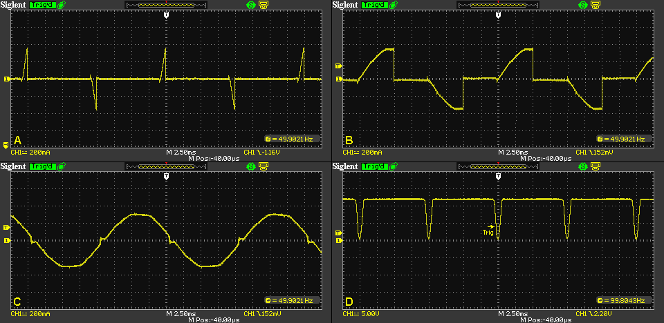
Figure 3 - Waveforms Taken From Prototype
The four waveforms show the current through the lamp at minimum (A), 50% (B) and maximum (C), and the zero-crossing signal (D). In each case, the 555 is triggered and the MOSFETs turn on at the zero crossing point (as the voltage shown in 'D' falls below 4V, and shown as 'Trig'), and turn off after the 555 has timed out. At low settings, the timer ends very quickly (a bit under 1ms), and as the time delay is extended more of the mains waveform is allowed to pass before the MOSFETs switch off the current to the load. The maximum delay is about 9.1ms (seen in 'C'). If you look at the waveforms carefully, you will see that the MOSFETs turn on just before the AC waveform actually passes zero. This is not a problem.
These waveforms were captured directly from my prototype circuit, which was supplied via an isolation transformer so the oscilloscope didn't create a hazard (or a (perhaps partial) short circuit). DO NOT attempt to take measurements unless you are 101% certain of your ability to do so without killing yourself or your test equipment. When connected to the mains, every part of the circuit must be treated as being lethal, because it is!
Because of the high voltages that the circuit operates with, construction is critical for user safety. Most will also prefer that using the dimmer doesn't cause their house to burn down, so cutting corners isn't recommended. While the timer, zero crossing detector and power supply (not including the series resistors) can be built using Veroboard or similar, the high voltage circuits must be assembled using tag strips or some other means of providing mechanical stability and electrical safety. Veroboard is unsuitable because the tracks are too close together, are very thin and aren't rated for the current that the circuit can draw.
You actually can use Veroboard, but you must be able to remove entire tracks (or parts thereof) to get acceptable spacing between high voltage points in the circuit, and any track that carries the load current must be reinforced with tinned copper wire to ensure it can carry the current without melting. This is the approach I took with the prototype that was used to create the waveforms shown above.
Be particularly careful with the pot. The insulation of 99% of pots is nowhere near good enough to protect against electric shock, and most have metal shafts. A plastic knob is absolutely essential, and it should be impossible for it to come off during normal use. If the knob is held in place by a grub-screw, you'll need to ensure that the head of the screw is deep enough to allow you to press a piece of silicone or rubber into the hole so that the screw can't be contacted. It is possible to get pots with plastic shafts, but they can be difficult (or even impossible) to get from some suppliers. You'll have to search your suppliers' catalogues to find them. Ideally, use a plastic shaft if you can get one, because it's extremely safe and makes the choice of knob simple - you can use anything you like that fits the shaft.
A PCB would be ideal, but there are no plans at present to make one available. This might change if there is enough interest. Making this dimmer small enough to fit the space available in typical switch boxes will be challenging. Standard 2-wire dimmers in Australia are very compact (roughly 25 x 25 x 34mm) and trailing edge/ universal types make extensive use of SMD components so they can fit the wall plates without getting in the way of switches and wiring. In general, SMD is not suitable for home construction because the parts are so small and often aren't available in small quantities. Having to buy 1,000 resistors when you only need one or two isn't something that most people will be happy about. Because there are at least 4 resistors that run fairly warm (all 1W), SMD parts aren't really suitable.
Note that C4 (47uF 25V electro) must be located as close as possible to the 555 timer, otherwise supply glitches caused by the 555's switching output may cause problems. The 7555/ TLC555 CMOS version is not critical, and C4 doesn't need to be particularly close to the IC because high current isn't drawn by the output stage when it changes state. The remainder of the power supply can be located anywhere that's convenient.
It's is hard to recommend a remotely mounted pot due to the relatively high impedances present. If hum or noise is picked up on the pot leads, this will cause erratic operation. I have tested and verified this, and injected noise can cause lamp flicker, half wave operation and extreme sensitivity to any control signalling on the mains. I strongly suggest that the pot is wired close to the 555 timer, with a minimum of lead length.
The power supply shown (R5, R6, D1, D2, etc.) is as basic as they get, and unfortunately it's half-wave which is frowned upon by energy suppliers. However, it's very low current so won't cause any problems with the mains. It will dissipate just under 1 watt all the time when the mains switch is closed. The DC component is about 3.3mA - not much, but it adds up. As already noted, a capacitor fed supply can't be used because the cap will be passing spikes from the MOSFET's switching waveform. This leads to very high peak dissipation in the series limiting resistor. The small DC component can be minimised using an additional diode, but that doubles the dissipation in R5 and R6, so cannot be recommended.
The alternative is to use a miniature switchmode power supply. I used one of these for my first prototype using a standard 555 timer, and it works well and has no problems at all - so far. Of course there are downsides, and they include size, cost and reliability. The cheapest 'name brand' AC/DC converter will cost at least $12, but most cost more. You can get a small SMPS from ebay (that's what I used), and while they are cheap (less than $3.00 each for the one shown below), the smallest I've found measures 32 x 22 x 18mm. The Recom RAC01-SC series would be suitable, but they are slightly larger again and considerably more expensive. If you decide to use a SMPS, make sure that it has a 12V DC output and that the AC input range suits your mains voltage. The converter must have a fully isolated output, so there is no electrical connection between the AC and DC sides. Minimum isolation voltage should be 1kV.
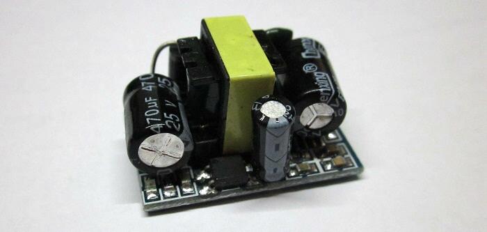
Figure 4 - Miniature SMPS Example
This is a photo of the SMPS I used. It's of Chinese origin, and is mostly surface mount except for the transformer and filter caps. Construction is pretty good overall, but that really doesn't tell us very much. The main area of uncertainty is "how long will it last?", and this question simply cannot be answered without running it until it fails. Naturally, if the power supply fails so does the dimmer, and we are used to dimmers lasting for many years.
Overall, using a switchmode supply is a good option, especially if a standard 555 timer is used. It's up to the constructor to decide which way to go for the supply. If you plan to run these dimmers at significant power levels (over 200W of lighting), then the SMPS is a much better choice. The entire 555 circuit only needs about 12mA, but the smallest SMPS I've found is 1W (84mA), so it will be idling during use. Note that the power supply cannot be shared across multiple dimmer units, and each dimmer must have its own power supply.
Figure 5 - Using A Switchmode Supply To Power Dimmer Circuit
The above shows the general scheme for using a switchmode supply. The supply's input is wired directly between active and neutral, and the 12V DC output is wired as shown. You still need C4 wired as close as possible to the 555 timer, but you can reduce it to 10uF if you wish. R4, R5, R6, D1, D2 and C3 are not used in this version. One benefit of this approach is that there is no effective DC superimposed on the mains. With the simple resistor limited supply shown in Figure 1 there is a net DC of about 2mA, which isn't a problem, but is less than ideal.
You could use a traditional transformer based linear supply too, but that will be considerably larger and heavier than any small SMPS. Of course, it will also be extremely reliable, something that must be considered if the dimmer circuit is installed in a difficult location.
I've run a barrage of tests on both of the prototype units, and they work extremely well. Although the captured waveforms were taken with an incandescent lamp as the load, I also ran tests with a couple of dimmable LED downlights, and was even able to get a usable dimming range from a couple of non-dimmable CFLs. The current waveforms were well within the normal range, and dimming to around 30% was quite satisfactory. However, standard CFLs will have a greatly shortened life if dimmed, so that isn't recommended. A conventional 2-wire dimmer was completely useless with the CFLs, and would be considered marginal at best with the dimmable LEDs. In most cases, the design of the dimmer (and the lamp) have to complement each other, and many 'dimmable' LED lights are incompatible with some dimmers, so the results are hit-and-miss.
Some non-dimmable LED lamps will also be able to be dimmed, but only if they are designed for normal 230V mains. Wide range (85-250V) types cannot be dimmed, because their internal power supply (aka 'ballast') will provide full light output once the voltage is above the minimum - regardless of the mains waveform. At low settings (at the threshold of normal operation), non-dimmable wide range LED lamps are likely to flash on and off. Again, I verified this during testing.
As expected, the 3-wire dimmer outperforms any 2-wire type on all loads, although there's not a great deal of difference with an incandescent lamp. However, even with an incandescent lamp, full power really is full power, and very little mains voltage is 'lost' across the dimmer. This general class of dimmer should be the standard today, because 2-wire dimmers are simply unsuited for use with electronic loads.
The circuit is more complex (and expensive) than a TRIAC based wall-plate dimmer, but it provides close to perfect 'text book' performance with any dimmable lamp. The complete absence of 'pop-on' and other undesirable effects that are common with 2-wire dimmers are the standout features of the circuit described. I have quite a few 'name brand' dimmers that I use for testing, and both circuits shown work better and are more predictable than any two wire dimmer with any lamp tested. There is simply no comparison - this dimmer is as close to an expensive programmable home automation or professional lighting dimmer as you can get.
Note that there is no mains filter shown, but the use of one is essential if the dimmer is expected to pass 'conducted emissions' tests under IEC or similar standards. As shown (without a filter) the circuit is guaranteed to fail IEC 61000-3-2-2014 or any subsequent/ equivalent standard. The minimum filter will use a common-mode inductor and at least one X2 Class capacitor.
There are no references because there are no sensible descriptions on the Net, other than things that I have written on the subject. I have searched long and hard, and the closest thing I've seen anywhere is wrong and can't work. There are also some forum discussions that are less than helpful to anyone - especially the person who asked the question in the first place! As of 2018 there is a bit more info, but much of it is still either based on ideas that (still) don't work or images from this page.
There is no point referencing circuits that don't work, and even less point referring to any forum discussion.
 Main Index
Projects Index
Main Index
Projects Index