
|
|
| Elliott Sound Products | MOSFET Relays |
 Main Index
Articles Index
Main Index
Articles Index
This article concentrates on MOSFET relays for speaker protection - disconnecting a faulty amplifier from the speakers to minimise damage. However, they are increasingly used in industrial applications due to indefinite life and faster operation than electromechanical relays (EMRs). One thing you won't find is a miniature MOSFET relay that can handle the output of a typical 100W power amplifier. Of those that can handle the voltage and current, most are based on a TRIAC (bidirectional thyristor) or SCRs, and they are completely useless for speaker protection. It's unrealistic to expect a tiny SMD MOSFET relay to be able to handle ±50V or so at 13A or more, and that's what's needed for speaker protection, along with high power industrial processes.
There are many small MOSFET based SSRs available now, but you have have 'high' current of up to perhaps 2A or so or high voltage (up to 600V), but not both. Most are based on a photovoltaic coupler (essentially a stack of miniature photo-cells), and they are generally fairly slow, although much faster than EMRs, and with no contact bounce. 'On' times vary from around 200μs to 2ms or so, with high-voltage, low-current devices being faster than those designed for low 'on' resistance (RDS on).
If you need to switch a few hundred volts at several amps, you have no choice other than to buy a very expensive commercial product, or build your own. For many applications, you may even want to consider a hybrid relay - a combination of an SSR for switching, and an EMR to carry the load current. These are covered in the article Hybrid Relays, and are ideal for many otherwise difficult loads.
Mains switching Solid-State relays (SSRs) for AC have been around for nearly as long as the first SCRs and TRIACs became available. However, none of these early devices was suitable for use with audio signals, because of gross distortion around the zero-crossing point of the waveform. They also cannot switch DC, because TRIACs and SCRs rely on the current falling to zero to allow them to turn off. MOSFET based SSRs have existed from around 1984, when a patent was taken out by International Rectifier Corporation for a MOSFET circuit that could handle AC with very low distortion. [ 1 ]. It is not known if this is the earliest example, but it's probably close.
There are any number of SSRs available that are suitable for DC, but comparatively few low-distortion types that can handle the high AC voltages and currents that are typical of high power amplifiers. Those commercial devices that might be electrically suitable will most likely do some serious damage to your bank account. There are a many that can handle up to around 2.5A at voltages as high as 600V, but comparatively few that can handle the 30-40A or so that is needed for a high power amplifier driving low impedance loads.
While conventional relays can be used, they have a small problem ... when a high power amplifier fails and the output goes DC, there could be 100V or more with a load impedance of perhaps 4 ohms or less. Breaking 100V at 25A DC is a very difficult job for a relay, because the DC allows a substantial arc to be created across the contacts.
This arc is very difficult to stop, and the only way to actually protect the speaker is to earth the normally closed contact so that the arc is connected to the power supply common rail (earth/ ground). The relay will be destroyed, but the speakers will (probably) survive. Most mains rated electro-mechanical relays are limited to around 30V DC, but even with this seemingly low voltage it is still likely that the relay will be damaged if it ever has to protect the speakers.

Speaker Protection Relay Wiring
The above shows the wiring scheme that must be used to protect the loudspeaker. The earth connection is often neglected in 'protection' circuits shown on the Net, and the end result is that while it may happily pass your basic tests, it will likely fail when you really need it due to the DC arc.
Perhaps due to the known problems with electro-mechanical relays, there seems to be some interest in solid state relays on audio forum sites, but while some of the information is actually quite good, there are many misconceptions and often a failure to understand the things that can go wrong.
Note that the DC detector and control circuit (not shown - see Project 33 for an example) must be connected directly to the amplifier's output. If it's connected after the relay, fault induced DC will only be present when the relay is closed, so your speakers will be subjected to repeated pulses as the relay closes, DC is sensed, and the relay opens again. This process will continue until you switch the amp off. When the detector is connected to the amp output, the relay will never close because the fault condition is detected before the detector attempts to connect the speaker.
This article shows MOSFET relays for speaker protection, but there are countless uses for them in other applications, especially where high DC voltages are present, or for 'arcless' switching of AC power. When used as mains relays, great care is needed with all wiring and MOSFET selection, both for electrical safety and to ensure reliability under adverse operating conditions. A MOSFET relay offers several advantages over a more 'traditional' SSR (solid state relay) using a TRIAC or back-to-back SCRs. The biggest advantage is that you can control the switching speed to minimise EMI (electromagnetic interference), and that with the optimum choice of MOSFETs the voltage drop can be reduced. A TRIAC(or SCR) has fairly consistent 1V RMS voltage drop, so dissipated power is 1W per amp of controlled current, regardless of the supply voltage. At 10A, a dissipation of 10W is normal. Use of MOSFETs with a low RDS-On means that this can be reduced, especially at lower voltages. A MOSFET relay also has no issues with minimum (holding) current, as do TRIACs and SCRs. You can control milliamps to amps with ease.
As of December 2019, there's a new option. Section 10 has the info on the latest (and so far the best by a long way) MOSFET driver, specifically intended for MOSFET relays. With the introduction of the Si8751/2, the game has changed. While it's only available in an SMD package, that's not an insurmountable problem - see Project 198 to see the complete design.
Although I have shown IRF540N MOSFETs throughout, this is more a matter of convenience than anything else. While these will be suitable for some lower powered amps, they are not suited to very high current. The claimed RDS-On is acceptable (77mΩ for the 540, 44mΩ for the 540N), but there are much better MOSFETs available now, having RDS-On below 20mΩ. I leave it as an exercise for the reader to select MOSFETs that are suited to the voltage and current available from the amplifier to be switched. There are many to choose from, and it would be rather pointless for me to try to list all those that you may (or may not) be able to get easily where you live. You can use multiple smaller units in parallel, which may work out cheaper. The lower the value of drain-source resistance, the lower the distortion contributed by the circuit, and there's less power dissipated (and therefore less heat generated).
The general idea of an AC SSR is shown in Figure 1.2. Two N-Channel switching MOSFETs are used, with their sources and gates joined. The signal and load are connected to each of the drain terminals - it doesn't matter which is which, because the 'switch' is symmetrical. However, bear in mind that there are two MOSFETs in series, so the effective RDS-On is double that for a single device.
With no voltage between the gate and source terminals, the MOSFETs are off, so no current flows. Depending on the MOSFETs used, they will conduct fully when the gate-source voltage exceeds around 7 Volts. It is always a good idea to provide 10-12V gate drive to ensure that they always turn on fully. The zener diode you see is to protect the delicate insulation between the gate and MOSFET channel.
The gate insulation is typically rated for a maximum of around ±20V. Even a little bit of stray capacitance or resistance (moisture on the PCB for example) can easily allow the voltage to rise to destructive levels because of the very high impedance, and the zener is mandatory. Even drain-gate capacitance can cause problems if the zener diode isn't included.
While the concept is very simple, in practice there may be quite a lot of additional circuitry needed because the control circuit must generally be completely isolated from the switching MOSFETs. Two complete circuits are needed for stereo, even if they are driven by the same detector. This is because the two pairs of MOSFETs cannot be connected together in any way, other than sharing a common control drive circuit such as a dual optocoupler or miniature double pole relay.
Each MOSFET's voltage should be rated for at least 25% more than the supply rails of the amplifier with no load. This is due to the way the circuit works, and because of the possibility of instantaneous back-EMF from the speaker or crossover coil when the DC fault current is suddenly interrupted. It may be useful to include a MOV (metal oxide varistor) across the SSR switch terminals, or use a capacitor 'snubber' to prevent the likelihood of any destructive voltage spike.
When MOSFETs fail, they almost invariably fail short-circuit (like most semiconductors), and it is conceivable that a failure could go entirely unnoticed until your speaker catches on fire. It is essential to make sure that failure is rendered highly unlikely, or that some kind of test process be incorporated (which adds further complexity of course). Quite obviously, a conventional relay can fail too, but they are generally extremely reliable and have no sensitive electronic bits in them. However, expect the contacts to melt if you try to break a high DC fault current - especially with voltages above 30V DC.
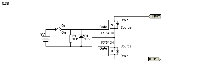
Figure 1.2 - Basic MOSFET Relay
What we need to activate the MOSFET relay is a floating DC source. It must be electrically isolated from the amplifier's speaker output (and with high impedance) or it will either be damaged by the amp, or will damage the amp. For simplicity, the DC source is shown as a 9V battery (discussed further below). Then the DC is connected and disconnected as needed to switch the relay on and off (shown above by a switch). There are any number of different ways to implement the switching function, ranging from miniature relays, opto-isolators (either LED + LDR or LED + photo transistor) or by remotely turning the gate supply on and off by some means. The zener is used to ensure that the voltage is kept below that which may damage the gate's sensitive insulation.
Figure 1.2 shows the general form of a MOSFET relay, using a 9V battery as an example only. While IRF540N MOSFETs are shown, you must use devices that are suitable for the voltage and current to be controlled. This general circuit arrangement will work with millivolt signal voltages, all the way up to 230/120V mains with the right devices.
If you have ±100V supplies, the MOSFETs should be rated for at least 120V, as this provides a comfortable safety margin. You can add resistors in parallel with each MOSFET, which reduces the effects of stray capacitance and ensures that your safety margin is maintained. 100k is a good place to start, but this isn't strictly necessary (especially with the relay circuits shown further below). The likelihood of excessive voltage is most likely with the 'charge coupled' circuit in Figure 4.1.
Capacitance from the speaker output to earth must also be minimised, or there is a risk that the amplifier may oscillate. Ideally the floating supply should be isolated from any stray capacitance by series resistors. These damp the effect of the capacitance and render it harmless. Where an output coil is fitted to isolate the amp from speaker cables and other stray capacitance, the SSR should be between the coil and speaker terminal - never between the amp and coil.
Note that the MOSFET switch is completely bidirectional, and although it may seem that it must introduce considerable distortion, this is actually not the case. When the switch is closed and the MOSFETs are biased on, the only voltage that appears across the pair is due to their on resistance (RDS-On). With suitable devices, this resistance is very low and reasonably linear. Linearity is not as good when the 'switch' is off, but that's of little consequence. Bear in mind that any series resistance reduces damping factor, so if you happen to think that very high values are essential, you may be disinclined to add a circuit that adds resistance.
The choice of suitable MOSFETs is huge - so much so that I'll only attempt a couple of types for consideration. A popular and inexpensive part is the IRF540N. It's rated at 33A with a voltage rating of 100V, so it can be used with supply voltages up to about ±70V. Another worth considering is the IRFP240, 200V and 20A. RDS-On is higher than desirable, but 2 or more can be paralleled to reduce that. There are many others, and I leave it to the reader to find a device that suits the purpose and the budget. The total series resistance will be double the RDS-On of each MOSFET. With an amp current of (say) 20A peak, there will be a loss of 1.76V peak (1.25V RMS) across the relay, and a total power dissipation of less than 150mW.
Note that while it would be very convenient (and easy) to use a battery as shown above, that would be a really bad idea. Even though the MOSFET gates require minimal current, the battery will eventually discharge (via the resistor, which cannot be omitted) to the point where a significant voltage will appear across the MOSFETs because they are not switched on hard enough, and this will cause severe overheating and gross distortion. As an example, the circuit shown above has a distortion of 0.013% with 28V RMS applied (a 100W/ 8 ohm amp at full power).
Should the MOSFET gate bias voltage be reduced to 5V, the maximum output is dramatically reduced, and distortion becomes excessive at any level above around 50-60W. In addition, the MOSFETs will overheat badly, because normally they only need a very modest heatsink (if any at all). Once there is a significant voltage across them and they are passing current, they will dissipate power.
Having ruled out using a couple of 9V batteries (at least from a purely practical perspective), we have to find an alternative solution to provide the necessary voltage needed to switch the MOSFETs on. Switching them off is easy - just take away the voltage. Some of the options are as follows in the next sections.
Note that if you use a cap across the relay terminals as shown in following examples, there will be a small signal current that will be audible with high sensitivity speakers if the MOSFET relay is used for muting. Provided the 'clamp' diodes are used, the cap can be omitted, or you can use a MOV for protection. If used, the MOV must have an RMS voltage rating that is less than the rated breakdown voltage of the MOSFETs, but greater than the amplifier's RMS output voltage. Given that MOV devices have a rather broad tolerance and are only available with a limited range of voltages, this makes selection rather difficult.
Several manufacturers make photo-voltaic MOSFET drivers that seem ideal (they use an infra-red LED and a bank of photovoltaic-diodes or tiny 'solar cells' to generate the gate voltage) [ 2 ]. While they can be obtained fairly cheaply (less than $10 if you find a supplier), a few problems exist. They are ...
The final issue is the one that is likely to cause some grief, because most have an output current that's less than 100µA, with some below 10µA. This means that the MOSFETs cannot be switched quickly (on or off), so peak power dissipation may be unacceptably high during switching. Remember that all MOSFETs have a gate-source capacitance that must be charged and discharged when the MOSFET is switched on and off. Although this must be considered, it is still possible to get switching times in the order of a few milliseconds, and this will generally be considered acceptable.

Figure 2.1 - Photo-Voltaic MOSFET Driver
The arrangement shown above is fairly typical of the general scheme, and will work very well provided the optimum photovoltaic optocoupler can be found at a sensible price. Ideally, you will need a photovoltaic opto that can provide at least 50µA or switching times become embarrassingly slow. In some data sheets (and included above) you will see a JFET used to speed up the MOSFET's gate discharge and turn-off time. As shown, turn-off is almost instantaneous.
Note the pair of 'catch' diodes (D2 and D3) that connect to the amp's supply rails. (These diodes are also included in other drawings, as it is very important that they be included.)
This arrangement can also be seen if you have a look at the Vishay VO1263AB data sheet, but they use a P-Channel JFET. It is pretty much mandatory to include the JFET if you choose to use the photovoltaic isolator circuit, unless you use the circuit shown in Figure 8.1. In other circuits you might come across, a high value resistor (~10MΩ) is placed across the isolator's output, but this has a much longer turn-off time (perhaps 100ms or even more, depending on MOSFET gate-source capacitance). This will almost certainly cause excessive peak dissipation in the MOSFETs and lead to failure.
The opto's LED typically needs to be driven with around 10-50mA to work, depending on the device used. This current is easily supplied by the speaker DC detector circuit. Project 33 can do the job easily.
In case you are wondering, the JFET circuit shorts the MOSFET gate to source when there is no current from the opto. When the opto is active (supplying current), a voltage is developed across R2 that biases the JFET off, so it does not draw any current. With 50µA and a 2.2M resistor, the JFET is biased fully off. Because of the wide parameter spread of JFETs and photovoltaic isolators, you may need to experiment with the value of R2 to ensure reliable switching.
It is important to understand that there will be some voltage drop across R2, sufficient to bias the JFET off. This voltage is unavailable to the gates of the MOSFETs, so the already limited voltage from the coupler is reduced a little more. This may be enough to not allow the MOSFETs to conduct fully, a highly undesirable outcome. The extra resistance also means that the MOSFETs turn on slower than they otherwise would. The difference is not great, but is easily measured.
Using a small transformer is a good solution, and it only requires a simple rectifier and minimal filtering to drive the MOSFET gate. Since the transformer can easily supply 10mA or more, switching times are dramatically reduced. Unfortunately, a transformer coupled circuit also needs a driver circuit to provide a signal at the secondary (or secondaries). This should operate at 50kHz or more to minimise the size of the transformer(s). Not really a problem, but there's more circuitry needed which takes up potentially valuable space.
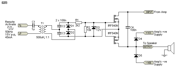
Figure 3.1 - Transformer Based MOSFET Driver
An example is shown above (just one of a great many possibilities), based in part on the original patent [ 1 ], but somewhat simplified. While it's not overly complex, there are nuisance issues like finding a suitable transformer that have to be solved. It will generally be easier to find single secondary winding transformers, so two will have to be used for a stereo system. If a single transformer with dual secondaries is used for a stereo amp, the insulation between the primary and also between both secondaries has to be able to withstand the full amplifier supply voltage. This means that if the amp uses ±60V supplies, the insulation has to be rated for at least 120V. It would be wise to ensure that all inter-winding insulation is rated for a minimum of 500V.
The drive signal typically needs to be a squarewave of no less than 15V peak-peak. The advantage of using a voltage doubler is that there is a small parts saving - the caps that form part of the doubler also smooth the DC. Without the doubler, either the drive voltage has to be increased or the transformers have to be step-up types to obtain enough gate voltage. There are a (small) number of new ICs that integrate the isolated coupler into the IC, but these are fairly new and may not be available yet.
Note that the diodes (D1 and D2) must be high speed types, preferably Schottky or at least 'ultra-fast' types. Normal diodes are far too slow and will cause very high losses in the rectifier - so much so that it may not even work.
The drive oscillator can be almost anything you like, but as noted on the circuit diagram above, you need at least 15V P-P drive voltage, at a frequency of around 50kHz. Current is fairly low at 45mA RMS for a transformer with 500µH primary inductance. Depending on the transformer you use, the current may be somewhat higher. There is no point trying to specify particular cores and formers, as their availability is highly variable - parts I can get here may be unavailable elsewhere and vice-versa.
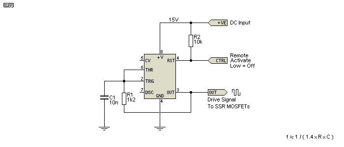
Figure 3.2 - Typical Oscillator
The oscillator shown above is the simplest possible arrangement using a 555 timer, but is perfect for this application. The output signal is close to a squarewave, and any small variation in duty cycle is handled by the capacitor feeding the transformer. This prevents any DC magnetic flux build-up that may cause the transformer to saturate. There are countless other oscillator designs that will also work, but few that are quite as simple as the one shown.
When the CTRL line is open circuit or high, the oscillator runs, and gate voltage is available to the MOSFET relay which turns on. When the CTRL line is pulled low, the oscillator stops and the MOSFETs also turn off once the gate caps discharge. It is possible to incorporate additional circuitry to ensure the relay turns off very quickly, but in reality anything up to a few milliseconds will be alright in most cases. A simulation tells me that as shown, it will switch off in under 1ms.
I tried an Ethernet transformer, with three windings in series, and having a theoretical inductance of ~250μH. Driving it with a 10V peak squarewave, I obtained an output of 15V DC using the doubler circuit shown next. The turn-on time is about 4μs, and turn-off time was measured at 25μs with a 2k load. This is significantly faster than any other option, and the high drive current will turn on the main MOSFETs more quickly than most other circuits. Even this can be improved, but only at the expense of greater complexity.
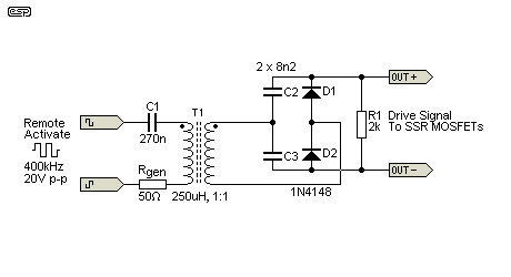
Figure 3.3 - Typical Pulse Transformer & Test Rectifier
The values are those I used (they were conveniently to hand when I ran the test). There's plenty of latitude, so you don't need to replicate the exact values I used. The transformer is a 23Z90 Ethernet pulse transformer, but anything similar will do nicely. The drive signal was directly from my function generator. There are many options for the oscillator, including something as basic as a CMOS hex Schmitt trigger (40106 or similar). The transformer is tiny - 11mm long, 6.8mm wide and 5mm high (excluding pins). The transformer will work down to 250kHz, but its low inductance starts to become a problem at lower frequencies. The drive current is about 26mA RMS (roughly 50mA peak), so it's a fairly easy load, even for CMOS ICs. The current can be reduced by increasing the value of R1, but unless C2 and C3 are also reduced, the turn-off time will increase.
You may also be able to use small 'output' transformers intended for low power transistor amplifiers (portable radios for example). These provide another option - just use the core and bobbin. Remove the existing primary and secondary, and wind new ones by hand. The inter-winding insulation layers can easily be improved to suit the new requirements. We are not overly concerned with efficiency, because the power needed is negligible. Unless you have access to small ferrite cores, this is likely to be the cheapest option.
As an alternative to using discrete circuits, it is also possible to use miniature DC-DC converters to provide both isolation and gate drive. This is a more expensive option though, but details are provided below in Section 5. While these will cost a little more than a full DIY approach, it's very easy to implement needing a minimum of additional parts.
There is the option of doing away with the transformer(s), and simply using low value capacitors to couple a high frequency AC signal to a rectifier circuit that then drives the MOSFET gates [ 3 ]. This arrangement is also known as a 'charge-coupled' circuit, and can use the same oscillator as shown above. Although the data sheet says that a 555 timer can operate at a maximum frequency of around 500kHz, I wouldn't be happy with it running that fast. Up to 250kHz should be fairly safe though.

Figure 4.1 - Capacitive-Coupled MOSFET Driver
Like the transformer solution, an oscillator at 50kHz or more is needed, and the coupling caps are so small that they will pass very little signal in the audio range. At the high switching frequency, the caps are almost a short-circuit, and can fully charge the gate driver within a couple of milliseconds. Current is quite low though, depending on the switching speed and capacitor value. High speed Schottky diodes are essential, as I would normally expect that switching frequencies well in excess of 100kHz be used. In the circuit shown above, the circuit can supply around 300µA, but can still switch MOSFETs on or off in a few milliseconds. The capacitors used should be rated for at least 600V DC.
The primary disadvantage of using capacitive drive is that the amp's output must be limited to no more than perhaps 25kHz or so. Should the amp decide to oscillate, there is a real chance that the capacitive driver circuits will be damaged. This will happen if any amplifier output frequency (intended or accidental) is high enough to pass a signal back from the speaker line to the driver circuit.
In addition, the voltage across C2 increases with increased amp output frequency, because the caps (especially C1) pass some of the signal and this assists the charging process. The only way to avoid this is to use a higher oscillator frequency and a smaller value for C1 and C3. For example, with an oscillator frequency of 500kHz and C1 and C3 reduced to 470pF, an amplifier signal of 25kHz at full power causes no increase in the normal voltage developed across C2. Also note that although the RMS drive current is only around 5mA, the peak value is over 30mA with the values shown.
Switching times are passable. While turn-on is quite fast at about 1ms, turn-off is rather lethargic - it takes just over 3ms for the MOSFETs to turn off with the values shown, so dissipation under fault conditions will be rather high. Although turn-off time can be improved by reducing the value of R3, this demands a higher drive signal (either higher voltage or frequency).
For the reasons described above, I do not consider this a usable approach for an audio amplifier. There are too many factors that make it unsuitable. It can be used for switching mains (50/60Hz) without too many problems though. In that case, C1 has to be a Y-Class safety rated capacitor to ensure electrical safety. You will need to experiment to get reliable switching, and it may be necessary to reduce the capacitor values (C1, C3) as well as R3 to ensure that the mains waveform can't provide a charge into C2. Note that R2 can be omitted (replace with a short-circuit).
This is probably one of the least desirable ways to make a MOSFET relay, but with care it can be made to work quite well.
The final option is to use conventional small power supplies that can have their outputs fully floating. A small transformer with dual secondaries is one possibility, but there is a real risk that the insulation between windings will be unable to withstand the output voltage swing from powerful stereo amplifiers. When doing some initial tests, I used a 12V DC switchmode plug-pack (aka 'wall-wart') as the voltage source (it's actually built-in as part of my workbench system, but that's irrelevant).
A small 50/60Hz transformer with dual windings can be used, having a conventional rectifier and filter cap on each output. As with the transformer drive approach, inter-secondary insulation has to be up to the task. This is actually rather unlikely, so it's hard to recommend this approach - it's much safer to use two transformers, but that gets bulky and rather costly. The DC to the MOSFET gates is simply switched using optocouplers with transistor outputs as demonstrated in Figure 6.1.
This kind of approach certainly works, but the cost and space is such that you'd be a lot better off financially by using miniature DC-DC converters. It's hard to recommend the use of separate mains powered transformer supplies as it is somewhat clumsy, physically large and comparatively expensive. However, it does offer a simple and easily implemented solution, with the minimum number of electronic bits to fail.
Commercial DC/DC converters are now readily available for well under AU$10.00 which are pretty much ideal. They have high isolation voltage, and have power ratings as low as 1W. This is as much as you'll ever need to power a pair of MOSFET gates (by a good margin). An example is the Murata MEU1S1212ZC, a 12V to 12V converter, at 6.1 × 8.3mm (width × length) and 8mm high, they are small enough to be easily incorporated into almost anything. There are many examples, but most are a little larger than the Murata unit. With 12V input versions needing less than 20mA (no load) input current, there's no strain on auxiliary power supplies.
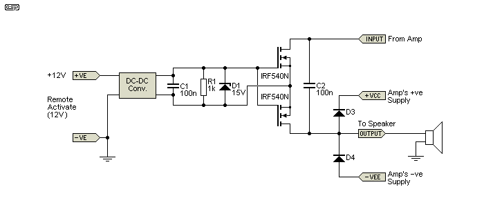
Figure 5.1 - DC-DC Converter Gate Bias
This is a fairly elegant solution, and allows for fairly rapid turn-on and turn-off, with a well defined voltage available from the DC-DC converter. A complete relay (one channel only) will cost less than $25 in parts (not including a heatsink for the MOSFETs), but is capable of handling high current and it can be adapted for any number of other tasks, not just as a speaker relay. The DC-DC converters are small enough to be able to fit in almost anywhere, and they typically offer at least 1kV isolation between input and output. However, note that this is usually the test voltage, and operating voltage is far lower. You absolutely cannot use these for controlling mains voltage unless the isolation working voltage is rated for 250V AC or more.
There is no requirement for power to be available full-time, because if the converter has no power the relay is off by default. Preferably, you'd also include an optocoupler, so that is used to turn the MOSFET relay on (and off). This is the safest way to wire the circuit. This is probably one of the better (and more flexible) solutions, as it can be adapted to many different applications easily. There isn't much info available on how quickly these converters drop their output voltage after input power is removed, but I ran a test using a 2.7k load resistor and the voltage collapses to (near) zero in a little over 10ms. An optocoupler can reduce that to less than 1ms.
This arrangement perhaps doesn't really look like it could work, but that's an illusion. By taking a diode blocked resistive feed from the positive supply, the DC is stored in C1 and because of the high impedances will hold up well even at low frequencies. C1 can't discharge back through the resistor when the amplifier's output voltage swings fully positive because the diode prevents this. Note that there is some modulation of the supply, but this is smoothed by the zener as it simultaneously protects the MOSFET gates.
The zener is absolutely essential in this arrangement (but should always be used anyway), because without it the voltage can rise to the full DC supply - gate destruction is a certainty. R4 is optional but recommended. The cap will charge whether it's there or not, as long as the amplifier or speaker remains connected (the MOSFETs' internal diodes provide the current path).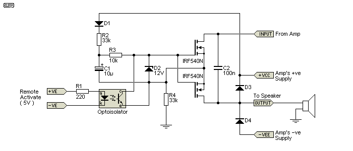
Figure 6.1 - Supply Rail Gate Bias
As shown, the supply resistor (R2) does provide a small DC offset current to the speaker when the SSR is turned off, but at less than 2mA with 60 volt supplies it can be ignored. This is by far the simplest way to obtain the necessary DC to keep the MOSFETs turned on. To switch them off, you may use an opto-coupler as shown, or even a small relay can be used. Note that R2 and R4 are suitable for supply voltages up to around ±50V. Higher values will be needed if the amp uses higher voltage supply rails. R4 can be connected to the -ve supply instead of earth if desired, but there's little point - the circuit won't work any better by doing so.
This circuit has the advantage of great simplicity compared to the other methods described. There is no need for an oscillator or transformers, no rectifiers or high speed diodes, and no side issues with high frequencies. Because of the continuous supply and use of an optocoupler, the turn-off time is also very fast. Turn-on speed is determined by the value of R3 and the MOSFET gate-source capacitance. We don't need sub microsecond switching, and in most cases the values shown will be more than acceptable.
It's also worth noting that the circuit doesn't actually have to be powered from the amp's supply rail. Any positive voltage source of 15V or greater is enough to allow the relay to turn on and remain on until the optoisolator turns it off again. It may be helpful if R2 is reduced to suit the lower voltage - about 22k is fine, but you might need to experiment a little. The second 'feed' resistor (R4) should be the same value. You may need to use 1W resistors with high power amps.

Note, however, that there are contra-indications to this technique. When used as shown and in the 'off' state, there is a small charging current that is rectified by the diode D1 and the MOSFET's intrinsic internal diode. When the cap is used in parallel, this tends to swamp the very small but highly distorted leakage current that flows each time the diodes conduct. While R2 (the bias feed resistor) does reduce the noise, you will hear a low-level distorted signal across the speaker. The capacitor (C2) tends to swamp this to a degree, but that allows even more signal to pass. None of the above affects the relay's ability to disconnect the speaker if DC is detected, but is something you need to be aware of. The distortion component of the muted signal is especially audible if you choose to use a feed voltage that's less than the full amplifier supply voltage, and you have very sensitive speakers such as horn compression drivers. For this reason, the MOSFET relay is not really suitable as a signal mute - this should be done at the amp's input or from the mixing desk.
BEWARE! - the relay's default state is ON! The external circuitry turns the relay off, but if the supply to the detection circuit is not present before the amplifier supply rails start to rise, DC can be fed to the speaker until such time as the detection circuits function and disconnect the load. This is easily circumvented by some additional circuitry or by leaving the detector permanently powered ... with the proviso that the amp cannot be turned on at all if the relay supply is not present!
For example, you could use P39 (soft start circuit), and use its power supply to power the detector (such as P33 which powers the optocoupler), as well as the soft start. While this adds some complication, a high power amp needs soft start anyway, so it's not necessarily a big deal.
It is possible to design the overall circuit so that the power supply constraints are reduced. Instead of placing the MOSFET relay in series with the amp's speaker output, simply connect it between the speaker common terminal (normally PSU earth/ ground) and the actual PSU earth bus. Now the entire circuit has one terminal that is earth referenced, which reduces the isolation requirements between the separate power supplies. However, when switched off, the centre-tap between the two MOSFETs can easily reach a voltage that still demands good insulation of any floating supply (roughly 1/2 the +ve supply voltage). The diode shown in Figure 6.1 (in series with R2) is not needed in the earth-referenced circuit shown below, because C1 cannot discharge when the amp's output swings positive - the junction between MOSFETs is at (close to) zero volts when the MOSFET relay is on.
This circuit doesn't actually need the optoisolator, and it can be used with a couple of transistors to provide gate voltage. However, if done like that it ideally needs a negative supply as well as the positive supply. Off performance is improved, but that doesn't matter if it's used as a speaker protection relay (allied with a modified version of Project 33 for example). The default state for the relay is ON, so the external circuitry is used to turn it off.
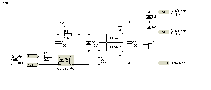
Figure 7.1 - MOSFET Relay Circuit In Earth (Ground) Line
Needless to say, this method cannot be used with BTL (bridge tied load) amps regardless of bias supply type, because each side of the speaker is driven by a separate amplifier driven 180° out-of-phase with the other. Both speaker terminals are therefore 'live' with the amplified signal, so a fully floating system is definitely required. Even if you do decide to connect your MOSFET relay in the earth end of the speaker (i.e. the speaker return), I still recommend that the power supplies are properly isolated or you may have unforeseen problems (assuming that you use one of the other methods shown, not the one in 6.1). I don't know what they might be, because they are unforeseen  .
.
Another potential issue is the added resistance in the speaker line, and that will reduce 'damping factor' (assuming that you consider it to be important) and output power. Any voltage and current combination that appears across/ through the MOSFETs also causes heating. For these reasons, using MOSFETs with a very low RDS-On is essential. The lower this resistance, the less distortion the circuit contributes as well.
The circuit shown is not perfect, and it will probably let a small 'leakage' current through with negative output voltage. The simulator says about 5mA or so, which is audible (200µW into 8Ω) but is unlikely to cause any issues. Attenuation is 40dB, so extraneous leakage signals will be very quiet. It's possible to improve it, but the circuit described in Section 10 is so much better that pursuing a simplistic approach isn't worthwhile.
It is possible to use a conventional relay in parallel with the MOSFET relay, so that there is no added series resistance. In the case of a fault, the relay must open first, followed by the MOSFET relay. This process will add an inevitable delay, because you must allow sufficient time to allow the electromechanical relay to be fully open before the MOSFET relay opens. The control system will also be far more complex, with more things to go wrong.
Based on simulations and some tests, distortion can be expected to be well below 0.1% unless you don't have enough gate voltage or RDS-On is too high. Remember that there are two sets of RDS-On in series with the speaker, so maintaining a very low figure for each MOSFET is essential. It may be necessary to use two or more MOSFETs in parallel on each side of the switch to keep the insertion loss as low as possible. For a high power amp, even 0.1 ohm represents a significant power loss, and that power is turned into heat in the MOSFETs. Any increase in temperature further increases RDS-On, causing higher losses and more heat. Thermal runaway is possible if the MOSFETs are not sized correctly.
The solution that you eventually use will be determined by a number of factors, including space, cost and switching speed. As always, there are trade-offs that must be made in any design to get a final circuit that does what's required, but doesn't compromise the internal layout or add excessive cost and complexity.
Photovoltaic optoisolators are a good solution, but the JFET (or the scheme shown in Figure 8.1) is mandatory to ensure fast turn-off times. The greatest obstacles you will face with this technique are cost and availability of suitable photovoltaic devices. There's a wide range available, but some will struggle to provide enough voltage to ensure the lowest possible RDS-On. Others have very limited current - perhaps 20µA or less. These will have rather long turn-on times, but that's not a major limitation - simply mute the amp's input until the MOSFET relay is turned on.
A transformer coupled system that uses squarewave drive needs very little capacitance after the rectifier to get a clean DC switching waveform. This means that turn-on/ off times can be quite respectable, without having to resort to using opto-couplers. Once the oscillator is stopped, the relay will switch off within a millisecond or so.
The high frequency transformer drive arrangement is also fairly straightforward, and will probably work out cheaper than using photovoltaic isolators. You can almost certainly make your own transformer quite easily - at 50kHz or so you don't need many turns, so it can be wound by hand. Naturally, the secondaries must be insulated to a standard that suits the amp's output voltage - both from the primary and each other. Another possible source of suitable small transformers is to use those tiny transistor output transformers that most electronics suppliers sell. Although they are extremely basic, some suppliers ask rather silly prices for them (up to $5-6 each). While they are basically rubbish in terms of audio quality, that's the least of your concerns when they are driven with a 50kHz squarewave . Their insulation may not be appropriate for a high power amp though, and this would need to be tested.
As noted earlier, I cannot recommend the charge coupled driver for use in an audio amp. It may be suitable for switching mains ... in which case the coupling caps (C1 and C3) must be Y2-Class (certified) types. All circuitry must have the required creepage and clearance distances for separation of hazardous voltage from your control electronics.
Using separate DC supplies (whether via a mains transformer or miniature DC-DC converters) is expensive and rather clumsy. It's hard to recommend this approach, but it may be required for some less pedestrian uses for a MOSFET relay. Since isolated switchmode DC-DC converters are available with over 1kV isolation, the technique is suitable for switching mains, provided transistor output optoisolators are used for MOSFET control. Be careful with these DC-DC converters though, as some have an isolation test voltage of 1kV, but the allowable working voltage is much lower (40-50V typical).
If you do use floating fixed supplies, you need to decide whether to switch the supply on and off to control your relay, or leave the supply running and use an optocoupler to control the gate voltage. The opto approach has a definite advantage in speed - it's easy to achieve sub-millisecond switching times, but at the expense of additional components. Switching the power supply on and off can result in MOSFET switch-off times of 10s or even 100s of milliseconds, depending on the load resistance.
In terms of ultimate simplicity, the supply rail bias scheme wins hands down for power amplifiers. No oscillators or transformers, and very few parts, so there's not much to go wrong. Standard transistor output optocouplers are cheap and readily available, and the most expensive part of the system is the MOSFETs. This is the scheme that I would probably use, provided that the speaker relay isn't used for muting. It's unlikely that any alternative scheme can come close for overall cost and lack of complexity.
It is important to understand that it does cause a distorted signal to be produced across the speaker when turned off (especially when connected in the earth lead of the speaker oddly enough). This is of no consequence if the only goal is speaker protection, and it is by far the easiest to implement. If full muting is needed, you will need to use one of the other schemes. The circuit must also introduce a small amount of distortion when turned on, because the diodes still go into and out of conduction as the signal voltage varies. However, the amount of distortion is very low indeed, and is unlikely to be audible at any level. While I have attempted to test for this, I was unable to measure the distortion, but of course that doesn't mean it's not there.
It used to be quite common for power amplifiers to have meters on the front panel to show the power level. These also used diodes driven from the amp's output, and therefore introduced some non-linearity. As far as I'm aware, no-one ever heard the distortion created, and I expect much the same with the circuits shown.
The circuit shown below has none of the limitations of the other schemes, but is comparatively expensive because of the two optocouplers. This is really a 'cost-no-object' approach, having only one limitation - the MOSFET turn-on time. This can only be made faster by having a low impedance supply for the gates, something you can't get with photovoltaic isolators.
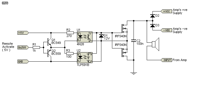
Figure 8.1 - Composite MOSFET Relay Using Dual Optocouplers
The arrangement shown above has many things to recommend it. Unlike the circuit shown in Figure 2.1, there is no series resistance and no JFET that must draw a tiny amount of current, thus reducing the available gate voltage and the resistor further limits the gate charge current. When the photovoltaic optocoupler is active, the transistor output opto is turned off, and all the available voltage from U2 is presented to the gates of the MOSFETs. When the input signal switches from 5V (MOSFETs on) to 0V (MOSFETs off), U1's output transistor shorts the MOSFET gates to the sources, ensuring fast turn-off.
The drive system is shown using 5V, but it can really be any voltage you have handy. It's just a matter of scaling R2 and R3 to get the right current into the opto's LEDs from the supply you have available. You may need to use higher voltage transistors if you want to use a voltage of over 25V or so.
Of course, disconnecting the speaker is not the only option. You can also use MOSFETs to switch off the amplifier's power rails when a fault is detected [ 4 ], however the circuit must latch so that the protection system doesn't cycle. This approach also has the limitation that you can't detect the fault before the speakers are connected, since the amplifier(s) need power to trip the protection circuits, so speakers will thump loudly when the amp is turned on.
The other version that probably has the widest application is that shown in Figure 5.1. It's fairly elegant, and I've used the small DC-DC converters in other (commercial) products I've developed with great success. While it's not the cheapest way to get a good result, it is still fairly cost-effective and it works quickly, which is what you need for a circuit such as this.
Although I have shown the various circuits here as speaker relays, needless to say this is only one of many applications. When switching DC loads, the schemes described here are not needed because the polarity will be known (so only a single MOSFET is needed), and for mains AC it's generally easier to use a TRIAC or a conventional relay.
There are many applications for the MOSFET relay in AC mains circuits though - trailing-edge light dimmers being one. In addition, if used with AC it is possible to use the relay to limit inrush current by turning on the MOSFETs relatively slowly. This may be hard to recommend though, because dissipation will be high and even a small asymmetry can cause an effective DC component that will cause serious problems for motors and transformers.
The number of applications is almost unlimited, but I confess that I can't think of many that haven't been covered already. Low current SSRs can be used for audio signal switching, and they are not particularly expensive. While this method of switching would satisfy most consumer audio requirements, it is probable that most people who love to build hi-fi equipment would frown upon the idea of active switches. CMOS active analogue switches already exist, but it's rare to find them in the audio path of any hi-fi equipment.
Even when switching high power circuits, there is usually no good reason to add the extra complexity. In general it's far easier to use a more conventional approach - traditional relays, TRIAC solid state relays, etc. However, it's also important to know about other techniques that might just prove to be the perfect answer to a problem that appeared to be insoluble.
A recently available MOSFET driver is the Si8751/52 capacitively coupled device, which was released in 2016 (it takes time before new devices are available from distributors). Unfortunately, they are only available in an SMD package, but with a rated working isolation of 630V (and a test voltage of 2.5kV) that provides sufficient isolation for most mains rated applications. Depending on local requirements, the low-side (transmitter circuit powered from a 3.3V to 5V supply) may require a mains protective earth. For speaker relays and other low voltage applications, no special precautions are required. There's been a lot of design work on these to make them as flexible as possible.
Apart from the Si8751 IC itself, mostly you only need a 5V power supply, a couple of resistors and a capacitor. The output MOSFETs will be selected for the voltage and current needed for your application. I've shown an AC MOSFET relay, but the IC is just as capable for DC. Although it's a great deal faster than any of the optocouplers examined here, it's not designed for high speed switching. The datasheet suggests an upper limit of 7.5kHz, but even that may be a little adventurous.
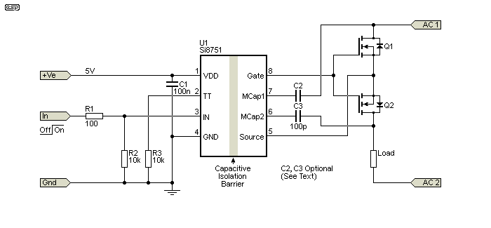
Figure 10.1 - MOSFET Relay Using Si8751 Capacitive Coupler
Turn-on and turn-off times are significantly better than photo-voltaic optocouplers, with typical figures of 42µs (on) and 15µs (off). This makes them an ideal choice for any MOSFET relay, and IMO pretty much renders the other methods obsolete. The only down-side is the fact that only an SMD package is available (SOIC-8). At a bit over AU$2.00 each when I bought them (late 2019), they are economical as well. For backward compatibility with optocouplers, the input of the Si8752 emulates an LED, the idea being that no circuit re-design is needed. The Si8751 uses a logic level input.
There's provision for 'Miller' capacitors, with the idea being that they will prevent the MOSFET(s) from turning on with fast transitions on the applied signal. For audio work (and anywhere else where very rapid voltage transitions are not expected) these can be omitted. R3 (connected from the TT pin to ground) is used to control how much current the circuit draws from the 5V supply. It can be shorted to ground (17mA), use (for example) a 10k resistor (9.5mA) or left open (1.8mA). This determines the switch-on time, with high current giving a faster turn-on.
The typical MOSFET gate 'on' voltage is 13V, but the datasheet does say that it may be as low as 9V. Most 'normal' (i.e. not logic level) MOSFETs will be quite happy with this, but you need to verify that from the MOSFET datasheet. If you want to find out more about these, a web search will provide the datasheet. This is the first IC I've come across that really makes MOSFET relays the 'go to' option for switching anything from mains voltages through to loudspeaker protection.
These ICs also allow the use of an N-Channel (or P-Channel, with gate and source pins swapped) MOSFET for high-side switching, with no requirement for bootstrap capacitors or other components. They aren't suitable for switchmode power supplies though, as they aren't fast enough. They are also not suited for any application that requires linear control - the MOSFET(s) are either on or off. Since they are designed specifically for MOSFET relays, this should come as no surprise. That they outperform anything else available is a given, as none of the other techniques examined in this article even come close.
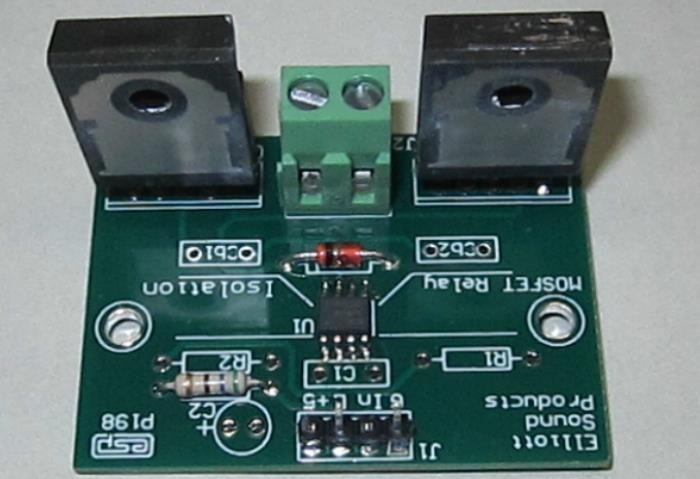
Figure 10.2 - MOSFET Relay Using Si8752 And Project 198 Board
The above shows my prototype, using the P198 PCB, and using a pair of STW20NK50Z MOSFETs. These are 500V, 20A, 190W devices that I happened to have on hand (removed from a SMPS that had failed). It pretty much goes without saying that it performs exactly as expected, and I have run a few 'definitive' tests, and turn-on and turn-off times are as shown in the Si8751 datasheet. The DC output from the IC measured just under 11V, more than sufficient to fully turn on the MOSFETs.
The MOSFET relay has been tested with an audio amplifier to turn the speaker on and off, and also with a 50W LED floodlight from the 230V mains. It works perfectly in both applications, and is at least reasonably safe with mains voltages due to the large area of creepage and clearance distances. With the MOSFETs I used, it should be able to handle a 230V load of up to around 500W (a bit over 2A) without needing heatsinks for the MOSFETs, as they will dissipate about 800mW each. Higher current will require heatsinks to maintain a safe operating temperature. There are many MOSFETs with significantly lower RDS-On that will dissipate less power, especially at lower voltages.
For a MOSFET relay project, see Project 198, which shows a complete circuit, based on the test board shown above. It's been tested for mains switching, lamp dimming and loudspeaker switching, and it does exactly what's expected in each case. It's shown using IRF540N MOSFETs, which are suitable for speaker switching, and can be used with the Project 33 loudspeaker protection board. A MOSFET relay is ideal when the DC supply voltage is too high to prevent relay contact arcing.
There are literally thousands of MOSFETs to choose from, and you will need to select devices that can handle the voltage and current you will be switching. For a loudspeaker protection relay, there are several suitable candidates shown in the Project 198 construction details (available to purchasers). You need very low RDS-On for high current, and a voltage rating that will suit your power amps.
Ultimately, it's up to the constructor to decide on the most suitable MOSFET for the intended purpose, and ESP makes no assurances one way or another. Sometimes, you'll have a limited choice and will have to make do with what you can get. The lower the RDS-On the better, and the voltage rating should be around 10-20% higher than the amplifier supply rails.
The datasheet for the Si875x ICs provides no information on just how the Miller clamp circuitry works. The circuitry is integrated, and presumably the manufacturer either imagines that people will know somehow, or they are trying to keep it 'secret'. While I figured it out fairly quickly (once I decided that people might want to know), there are many documents on the Net that describe Miller clamps. They are particularly important with SiC (silicon carbide) MOSFETs due to their different internal structure, but very fast voltage risetimes can cause issues with standard silicon MOSFETs as well. You'll quickly discover that most of the info available on-line is either application notes or academic discussion. You be hard-pressed to find many example circuits that show how it's implemented.
All semiconductors have inter-electrode capacitance, and the capacitance between the drain and gate (the Miller capacitance) is the most important. Mostly, this isn't a problem because MOSFETs are usually driven from a very low impedance, but the internal circuitry of the Si875x ICs has considerably higher effective impedance. This allows a fast risetime drain voltage to cause spontaneous conduction of the switching MOSFET. It might only last for a microsecond or so, but it can reach a high current, limited only by the external impedance.
The Si875x datasheet is unclear about the 'gate-off' impedance. While it claims that it's over 1MΩ, this is highly unlikely. It's not something I've been able to verify, but from performance measurements it would appear to be around 22k. Provided the DVDT (ΔVΔT - rate of change of voltage vs. time) remain below 10V/ µs it's unlikely that there will be any issues. That may not sound very fast, but it's equivalent to a 50V RMS sinewave at 20kHz.
The parasitic capacitances for a MOSFET are shown shaded. These are (in order of importance) CGD - gate to drain, CGS - gate to source, and CDS - drain to source. Spontaneous conduction is caused mainly by CGD, because the rising voltage on the drain is partially coupled to the gate. If the drain voltage changes quickly enough, it should be apparent that the MOSFET will conduct, but only while the drain voltage is rising.

Figure 12.1 - Active Miller Clamp Demonstration Circuit
In the drawing above, I've only shown one switching MOSFET, Q1. Q2 is the Miller clamp. When the drain voltage DVDT is very short (e.g. 10µs or so from zero to maximum) the switching MOSFETs Miller capacitance will cause it to turn on - as the voltage is changing. By using a capacitor to differentiate the critical rate of change to the clamp MOSFET, the clamp turns on and shunts the parasitic gate current to the source. The switching MOSFET may have the DVDT current reduced from many amps to only a few milliamps at most.
The Miller clamp is shown as a small-signal MOSFET, but a bipolar transistor can also be used. In a simulated comparison between the 2N7000 MOSFET and a 2N2222 BJT, the difference was negligible
A simulation of the circuit shown (but with Q2 disconnected) indicates that a 10µs supply voltage risetime (from zero to 100V on the DC supply), the MOSFET will conduct 6.27A peaks (with current in excess of 1A for 22µs). When the Miller clamp circuit is connected, the peak current is reduced to 15mA with a duration of less than 1µs. Note that this entire process is irrelevant if the supply is steady DC, and it can only happen when the DC is turned on, and its DVDT is greater than 10V/ µs. In 'real-life' circuits this is very unlikely.
During my simulations, I found that a ΔVΔT of 100V/ µs would cause a (simulated) IRF540N to enter spontaneous conduction with a G-S resistance of 330Ω, passing a current of 4.5A during the voltage transition from 0-100V (in 1µs). This was reduced to 65mA with the active Miller clamp in place, using a 22pF capacitor. With a higher G-S resistance, the effect was a great deal worse. In the vast majority of cases, the Miller clamp caps will not be required.
This is a simplified explanation, so if you wish to get more in-depth coverage of the topic, I suggest a web search. The circuit shown above has been simulated, and the clamp does exactly what it's supposed to do. The demonstration circuit shown in Figure 12.1 reduces the peak switching MOSFET current from over 6A to no more than 15mA (most of which is due to CDS), based on a simulation using the devices (and voltage waveform) shown in the circuit. Despite everything described here, I can't think of any application where any problems will be experienced, but if they do arise the solution is provided in the IC.
While the MOSFET relay has some significant advantages over and above a traditional electro-mechanical relay, these advantages come at a cost. The MOSFET relay will be physically larger than a conventional relay, and the overall circuitry is more complex and costly. Where a relay can be glued into place on the rear panel of an amp, the MOSFET version requires at least one printed circuit board, as well as more wiring. While it will survive a DC fault in the amp (possibly many times over), DC faults are uncommon in well designed amps, used properly, and with good heatsinks.
To obtain complete isolation (full muting), you have to forego the parallel capacitor, and use a MOV and/or 'catch' diodes on the speaker side of the relay. With the cap shown in the above examples, there is a small 'leakage' current via the cap, and if the relay is used to mute the speaker output, a low-level signal is audible with sensitive speakers. Also, note the comments for my simplified 'supply rail powered' version - ignore this at your peril.
Yes, a conventional relay will be a real mess after the DC arc has been shorted to earth, and the relay should always be replaced if the amp has failed DC. However, the relay is cheap, easily replaced and you never have to worry too much about a multiplicity of electronic parts that can also fail, rendering the amp unserviceable even if there's no other fault. Contact resistance is sufficiently low as to ensure minimal power loss (if any), and distortion should be somewhere between zero and negligible if you have good contact materials and no oxidation. Once driven to power, any oxidation will be burnt away anyway - it is extremely uncommon for anyone to suffer from audible distortion caused by relays.
The MOSFET relay will survive countless DC faults, but this should never happen. All the additional complexity and cost is essentially wasted, with the exception of very high power amplifiers. It is extremely hard to find any relays that can break 100V DC at 25A or more - they exist, but are large and expensive. In such cases, it is worth considering the use of a final level of protection - a high power TRIAC that acts as a 'crowbar'. It protects the speaker by simply shorting the amp's output to earth. The amp has already failed, so additional damage is of little consequence because it will be limited when the fuse blows - which it will do spectacularly.
The important thing is to ensure that an amplifier failure only means that you have to repair the amp - not the speakers to which it's connected. In many cases, the loudspeaker drivers can cost more than the amplifier.
Naturally though, the idea of building your own MOSFET relay should have some appeal, just for the knowledge gained and the experience you'll get, not to mention the fun factor. I leave it to the reader to decide which method to explore and how much fun they should have doing so. The IC described in Section 10 really is a game-changer, and makes MOSFET relays far more usable than any other technique. I have retained the other techniques for posterity, but in reality they are all rendered obsolete with the availability of the Si8751 and Si8752 MOSFET driver ICs.
See Project 198 for a complete description of the MOSFET relay described in Section 10.
This is a space that's evolving, with new options being announced by the major IC manufacturers regularly. TI (Texas Instruments) has a new range of ICs for SSRs as of late 2023, but availability is limited at the time of writing. We can expect new developments as technology improves. It's already (more-or-less) possible to buy ICs that provide the equivalent of the transformer-coupled option shown in Fig. 3.1, but in a tiny SMD package. Most of these are hard to get though - they are listed as 'available', but the major distributors never seem to have them in stock. I have no doubt that this will change!
I also looked at a great many suggestions, websites and application notes - some good, some decidedly otherwise. The references shown above are intended as representative, and the same or similar information can be found elsewhere. A search is always a good place to start, but you need to know just what to look for in any circuit you may find. While some ideas seem ok on the surface, that's because the potential shortfalls haven't been mentioned (or addressed).
Main Index
Articles Index