
|
|
| Elliott Sound Products | Lighting Dimmers |
 Main Index
Lamps & Energy Index
Main Index
Lamps & Energy Index
Contents
Right from the outset, I must emphasise that this article describes dimmers (or 'dimmer switches' in the US) used in residential applications. High powered stage dimmers are not covered, and I also don't propose to discuss in detail C-Bus, DALI or any of the other home automation systems. While there are a great many similarities between the high and low end products, the automation process is almost completely digital in nature and can be implemented in many different ways to achieve the same end result.
Some jurisdictions in the US have mandated that dimming and/or occupancy sensors shall be used to minimise the energy wasted in office spaces and carparks (among other spaces). Expect that over the next few years this will become more widespread, in the quest to minimise wasted energy.
There are two main categories of traditional AC dimmers (also known as 'phase-cut' dimmers), commonly referred to 'leading edge' and 'trailing edge', and while either will work with resistive loads such as incandescent lamps, the choice is more critical for any lamp that includes electronics. There are probably even a few of the now very old (and extremely inefficient) 'rheostat' dimmers around, and possibly a few that are based on variable auto-transformers (aka Variacs). Because neither of the last two are common or will ever become common in the future, they will be described in general terms only.
Electronic transformers are now very common for low voltage lighting, and these have gained popularity because they are cheap and comparatively efficient. There is very little real information available for any of these devices. A few schematics exist on the Net for basic (leading edge) dimmers, and even some data on electronic transformers, but almost nothing about trailing edge dimmers and how they work.
All waveforms and calculations used in this article are based on a 50Hz, 230AC mains supply. Other voltages and frequencies can be extrapolated from the data shown. This was done in the interests of simplicity, and the general trends are identical for any voltage or frequency. The majority of waveforms shown are derived from a simulator rather than by direct measurement. This simplifies the process of making graphs, and also allows very detailed analysis of the waveform, it's power factor and harmonics. While actual measurements could have been used, these take far longer to prepare and have many uncertainties because of voltage waveform distortion, supply voltage variations and external noise and/or distortion.
One thing that is very unfortunate ... almost all domestic dimmers are 2-wire, and therefore have no neutral connection. This places many constraints on the dimmer and how well (or otherwise) it will work, especially with non-resistive loads. These standard series-wired dimmers work fine with incandescent lamps, because the lamp filament provides a continuous connection to neutral and the dimmer has a reference (at least of sorts). With electronic power supplies (CFLs, LEDs, etc.), this reference is not present until the lamp starts to draw current, and dimmer operation may be erratic at best or useless at worst. One way this can be 'fixed' is to use an incandescent lamp in parallel with the electronic lamp. A single (small) incandescent lamp can be used with multiple electronic lamps - provided of course that they are specifically intended for use with dimmers!
Finally, there are dimmers that are used with DC only. Previously only a curiosity (or used to control DC motor speed), these will get a new lease of life with LED lighting. Dimmable ballasts consist of switchmode DC power supplies, adapted to provide the constant current required by LEDs. Dimming is often achieved by switching the DC on and off very rapidly, and is almost lossless.
Unless otherwise stated, the voltage used for all examples is the Australian/ European standard of 230V at 50Hz. A full cycle takes 20ms, and the peak voltage is nominally 325V. For 120V 60Hz mains, the period of one cycle is 16.67ms and the peak voltage is 170V. Readers in the US will need to make the necessary conversions to suit the lower voltage and higher frequency.
 | NOTE CAREFULLY: It is extremely important that the reader understands that
dimmable electronic lamps (both CFL and LED) are commonly claimed to be compatible with leading and trailing edge dimmers. With very few
exceptions, this is not true! Almost all electronic lamps draw a very high peak current when connected to TRIAC (leading edge) dimmers, because the
rise-time of the mains input is incredibly fast. This places enormous stress on the dimmer itself, and more importantly on the lamp's electronics. Despite makers' claims, the lamp will almost certainly not survive the abuse for very long, so the lamp life is reduced - possibly dramatically. A trailing edge (or universal) dimmer does not subject the lamp to a fast rising waveform, so doesn't cause excessively high peak current to be drawn. |
It is important to understand that the standard 2-wire dimmer was designed to be used with incandescent lamps. Despite anything you will read elsewhere, operation will be unpredictable with ANY load that isn't an incandescent lamp! For reliable performance with electronic loads (dimmable LED or CFL lamps), the dimmer should be 3-wire (active, neutral and load). Unfortunately, these are uncommon and will usually be difficult to install as a retro-fit because most lighting switch boxes don't have the neutral available. 2-wire dimmers were designed for incandescent (resistive) lamps, and were never intended for use with electronic load.
I will use the term 'friendly' to describe waveforms that introduce little or no distortion into the supply grid, and which have a good power factor. Many people are under the impression that power factor is only relevant with inductive or capacitive loads, but this is completely untrue. Any current waveform that is not an exact replica of the voltage waveform has a power factor of less than unity (the ideal). It doesn't matter if the current waveform is simply shifted in phase or is non-linear, power factor is still affected. See Power Factor for more information.
Figure 1 shows an example of each of the above. Voltage is shown in red, and current in green. The amplitudes of the two waveforms are deliberately different so the two graphs are clearly visible. These graphs are not to any particular scale, but all power factors are adjusted to be as close as possible to 0.5, and power in each case is 52.9W. An additional 230mA is drawn from the mains, but does no useful work.
Figure 1 - Voltage and Current Waveforms
Since the voltage and current are simply multiplied together to obtain the VA rating, it's obvious that for the inductive and capacitive examples, the VA rating is 105.8VA, but the power is still the same, at 52.9W. The non-linear load is a special case, simply because it is non-linear. Power is 64.8W and the circuit still demands 105.8VA from the mains, but load power is 64.8W and power factor is 0.61 - a slight improvement, but it can't be corrected easily!
Whenever the VA rating and power rating are different (VA cannot be lower than power), excessive current is drawn from the mains, causing losses in distribution cables, transformers, substations and alternators. A 1MW alternator faced with a power factor of 0.5 can only produce 500kW, since it is ultimately limited by its VA rating. All electrical distribution system components are actually limited to a VA rating, not a power rating.
Figure 2 - Circuits Used To Create Voltage and Current Waveforms
Figure 2 shows the circuit diagrams used to produce the above waveforms for those who are interested. These are theoretical, in that actual loads are rarely as simple and usually cannot be represented accurately with so few components. However, the effect is sufficiently similar that these circuits are quite adequate to show the general trend. As many advertisements state in the fine print "actual results may vary".
Even though the power may be well within the nameplate rating on a transformer, if the VA rating is exceeded it will overheat. Continuous overheating will cause failure. Because of this, the supply companies and/or authorities worldwide need to have the best power factor possible to make maximum use of their equipment. Large installations will be penalised with additional charges if their power factor is not within the specified limits.
Waveforms like the last example are the worst, because there is very little that can be done externally to modify the waveform to reduce the non-linearities, and harmonics of the mains frequency are injected into the system causing further problems. A complete discussion of the havoc caused by non-linear waveforms is outside the scope of this article, but many countries have introduced (or have plans to introduce) mandatory power factor correction for all electronic loads above a given power limit.
To dim a lamp, the common approach is to reduce the applied voltage by one means or another. Very early attempts used a rheostat (a variable resistor) in series with the lamp, since there was no viable alternative at the time. This approach wastes an enormous amount of power, and it's probably well over 40 years since anyone made such a beast. This approach does provide a very friendly load to the supply grid, having zero switching impulses and a perfect power factor. Disposing of the excess heat is a challenge, especially for lamps of reasonably high power. Rheostat dimmers can be expected (if found) to be quite large because of the heat that must be dissipated.
A variable auto-transformer (commonly known as a Variac™) wastes almost no power and is as friendly to the power grid as a rheostat, but is an expensive (and bulky) way to dim lamps. The cheapest variable transformer currently available is about $150 and weighs several kilograms. While there is no doubt that this is a good approach, economics preclude it from general purpose use. Variac dimmers were common in TV studios until perhaps 20 years ago. You may see comments (elsewhere) that Variac dimmers are lossy and inefficient, but this is simply not true - they are very efficient, and rival the very best solid state (TRIAC, SCR or IGBT) dimmers. However, they are bulky and somewhat inconvenient for use as dimmers. Remote operation is achieved by using a servo-motor to adjust the wiper position and thus the output voltage. For more on Variacs in general, see Transformers - The Variac.
Another method that was used in the early days was a device called a 'magnetic amplifier' (or just mag-amp), but from what I could find, these were not common in anything other than fairly large industrial dimmers used for TV studio lighting. Like a Variac, a magnetic amplifier creates little or no interference, but they have been replaced by other methods. I do not intend to cover the principles of magnetic amplifiers here or elsewhere on the ESP site.
Today, the most common dimmer is the phase-controlled (aka 'phase-cut') leading edge TRIAC dimmer. A TRIAC is a bidirectional switching device, and requires only a brief pulse to turn it on. With an AC circuit, it will automatically switch off when the AC voltage polarity reverses. This happens because the voltage (and therefore the current) pass through zero. The TRIAC cannot remain conducting with zero current, so switches off. The process of switching on and off occurs 100 times each second (120 times for 60Hz mains). Household dimmers are evolving though, and the latest type is called a 'universal' dimmer. These can change operation from leading-edge to trailing-edge depending upon the load (see below for an explanation of the different types).
By varying the ratio between voltage on and off, a crude pulse width modulation scheme is created, and this allows the power to the lamp to be changed over a wide range. Incandescent lamps are ideally suited to this method of control, and give a pleasing and natural progression between almost off and (almost) fully on. Many cheap TRIAC dimmers available use the simplest possible circuit, so low settings may not be stable. At a mid setting, the RMS voltage from the half waveform is 162V, based on a 230V AC supply voltage.
Regardless of the method actually employed, the goal is to vary the power delivered to the lamp, allowing the user to set the light level appropriate for the occasion. No commonly available dimmer is capable of maintaining a good power factor (important for the health of the supply grid).
For reliable operation, dimmers should be 3-wire (active, load and neutral) to ensure that the mains waveform zero crossing point can be maintained accurately. No small dimmers are 3-wire because that would make installation more difficult, so with anything other than resistive loads such as incandescent lamps, the dimmer will often misbehave. The degree of misbehaviour depends on the type of load (especially electronic lamps such as CFLs or LED lamps).
Two-wire dimmers have no reliable zero-crossing reference point because they rely on the lamp's filament for the neutral reference. Electronic loads don't provide any useful reference because the charged capacitors (inside the lamp power supply) cause zero current for most of the waveform cycle. The dimmer therefore can't be on permanently (full power), because it takes time before the TRIAC can trigger. Adding an incandescent lamp in parallel with electronic loads can only work reliably with trailing-edge dimmers - leading-edge types should never be used with any electronic load.
 | Note Carefully: Non-dimmable CFL or LED lamps must never be connected to a dimmed
circuit - even if the dimmer is set to maximum. While not apparent, the current drawn by the lamp circuit can increase dramatically (5 times or more), and can
pose a fire risk as well as reduce the life of the lamp electronics. Even commercial dimmers that do maintain an accurate zero-crossing reference should not be used with CFL or LED lamps, or any other 'capacitor input power supply' load. In one installation that I know personally, the end user had close to 100% failures of LED tube lights connected through a commercial dimmer. The normal failure rate is less than 1%, but the suppliers of the dimmer chose to argue. The only difference between their installation and all others is the dimmer, therefore it can only be the dimmer causing the failures. Strangely, both the end user and the dimmer supplier seemed to have a problem with this simple concept. |
High power commercial dimmers often use SCRs (wired in reverse parallel), because these are made in much higher current ratings than TRIACs. Triggering is typically by high frequency pulses, delivered for the full duration of the 'on' part of the mains waveform. They have full 3-wire reference, and never lose their zero-crossing reference. Nonetheless, as noted above, even these dimmers cannot be trusted to function properly with electronic power supply type loads.
Also known as 'forward phase control' dimmers. These are currently the most common types, and are so called because the dimmer functions by literally removing the leading edge of the AC waveform. The active switch for low to medium power is almost always a TRIAC for typical domestic dimmers. When the TRIAC is triggered, the mains signal is applied to the load, with a delay period that ranges from zero milliseconds (fully on) to around 9ms (very dim). As an example, the voltage waveform across the load for a leading edge dimmer set to 50% is shown in Figure 3, with the first two cycles (in green) showed undimmed as a reference. This waveform is 'ideal', meaning that it is the result you'd expect from a circuit that worked exactly according to the theory. Most leading edge dimmers come fairly close to the ideal - at least with resistive loads.
Figure 3 - Ideal Leading Edge Dimmer Waveform
As noted above, leading edge dimmers must never be used with compact fluorescent lamps (CFLs) - even if the instructions specifically state that this is permitted. The very fast rising signal causes a huge current to flow through the main filter capacitor that is part of the lamp's ballast circuit. Most current LED lamps will have the same problem. I suggest that ONLY trailing edge or universal dimmers be used with any dimmable CFL or LED lamp.
The waveform below shows the current drawn by a 75W incandescent lamp connected to a leading-edge dimmer. The lamp is drawing 200mA. The risetime of the waveform was measured at 1.8µs - that is fast in anyone's language! With 230V mains, the voltage increases from zero to 325V in less than 2µs! It is this extremely fast risetime that causes electronic loads grief, because even with 'dimmer compatible' CFL or LED lamps, there is always some capacitance that is charged from almost zero to full voltage in less than 2µs. You can even see a small overshoot in the current waveform with an incandescent lamp! This is caused by the tiny capacitance of the lead from the dimmer to the lamp.
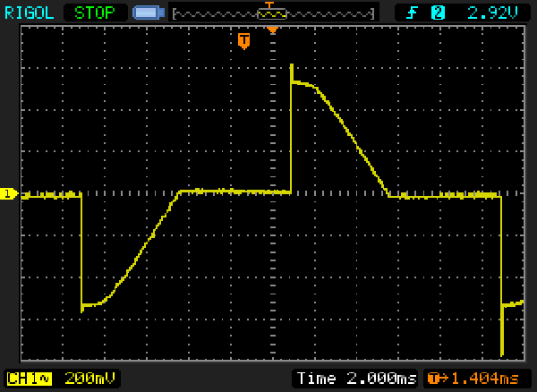
Figure 3A - Captured Leading Edge Dimmer Current Waveform
As an example, if an electronic ballast draws 83mA from the mains, this is sufficient to power an 8W electronically switched lamp (of any type). If no additional circuitry is used to improve the power factor, it will have current peaks of 270mA and a PF of about 0.42 - pretty poor, but certainly not unknown. If the exact same circuit is then powered via a dimmer, the worst case RMS current will rise to 240mA, with peaks of 4.2A. Power factor falls to 0.14 - a truly dreadful result. At this point, that lamp's power supply is drawing over 55VA from the mains, with a really nasty spike waveform. See Figure 2 (Non-Linear Load) for an example of a typical power supply front-end. The filter capacitor in Figure 2 (used to create the waveforms shown in Figure 1) is 18µF. This is not a common value, but was used to ensure the examples are equal. The charging current flowing into the capacitor is extremely high because the rate of change of voltage is also very high.
Figure 4 - Typical Leading Edge Dimmer Schematic
The circuit above is typical of a typical commercially available leading-edge dimmer. C1 and L1 are for RF interference suppression. The circuit operates by utilising the phase shift created by VR1, C2, R1 and C3. This network delays the signal applied to DB1 (a bidirectional breakdown diode called a DIAC). When the voltage exceeds the 30V (typical) breakdown voltage of the DIAC, it conducts fully and the charge in C3 is used to trigger the TRIAC. Once triggered, the TRIAC will conduct fully until the current falls to near zero, at which time it turns off again. This process is repeated for every half-cycle of the mains voltage. The delay, turn-on and turn-off points are visible and indicated in Figure 3.
Figure 4A - Leading Edge Dimmer Waveform Into Electronic Load
Leading edge dimmers must never be used with any electronic load (most electronic ballast circuits), because the very fast rise time of the voltage causes extremely high instantaneous current flow into the capacitor as shown above. Figure 4A shows current peaks of over 11A into the same non-linear load example used for Figures 1 & 2. The RMS current is 1.12A for a load power of just over 56W. Note that the load power has only fallen a small amount - from 64.8W to ~56W. The voltage waveform is exactly as shown in Figures 3 & 3A. 11A peak current for an RMS current of a little over an amp is extremely unfriendly to the grid, the dimmer and the electronic load. A standard 2-wire dimmer will present a waveform very similar to that shown even when set to maximum!
Perhaps surprisingly, inductive loads (such as conventional iron core transformers or common electric fan motors) are quite safe with leading-edge dimmers, because the inductance limits the rise time of the current to safe values. These loads must always use a suitable leading edge dimmer, which must be certified by the manufacturer as being suitable for motor or transformer loads.
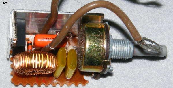
Figure 5 - Leading Edge Dimmer Insides
The black device on the left is the TRIAC. While it is fitted with a 'heatsink', contact between the heatsink and TRIAC is best described as accidental. There was almost no contact at all in this one when it was dismantled, however, it's been working reliably for 12 years and will likely last that long again. The simplicity of the circuit is quite obvious in the lack of sophistication of the PCB. The few components used are all through hole types, and there are no parts on the back of the board.
The circuit is almost identical to that shown above. The coil and orange capacitor are for interference suppression, but no fuse is fitted. If the dimmer were to fail short-circuit, the lamp will simply come on at full brightness.
While the makers of leading-edge dimmers often claim they are suitable for use with iron-core transformers, some most certainly are not. A common problem with simple TRIAC dimmers is that they go into 'half-wave' mode - conducting only on one polarity of the mains waveform. This is a disaster for any transformer, which will immediately draw a very high current, limited only by the primary resistance. It is probably better to use a 'universal' dimmer for inductive loads, because these have a much more sophisticated circuit and are far less likely to be 'tricked' into single polarity (half-wave) operation.
There is a complete schematic for a known working (i.e. built and tested) 3-wire leading edge dimmer in the ESP project pages. See Project 157B for details.
Also known as 'reverse phase control' dimmers. A trailing edge dimmer is a considerably more complex circuit. The simple circuitry that is common with leading edge types can no longer be used, because most TRIACs cannot be turned off. Gate turn-off (GTO) TRIACs exist, but are far more expensive and less common in the relatively small sizes needed for lighting. To be able to implement a trailing edge dimmer, the switching device must turn on as the AC waveform passes through zero, using a circuit called a zero-crossing detector. After a predetermined time set by the control, the switching device is turned off, and the remaining part of the waveform is not used by the load.
Trailing edge dimmers commonly use a MOSFET, as these require almost no control current and are rugged and reliable. They are also relatively cheap and readily available at voltage ratings suitable for mains operation. Another option is to use an IGBT (insulated gate bipolar transistor), which combines the advantages of both MOSFET and bipolar transistor. These are generally more expensive than MOSFETs. Again, the waveform is ideal, and it is obvious from the actual waveform shown in Figure 9 that there is a significant deviation - especially at full power. This is caused because some of the applied voltage will always be lost because the complex electronics require some voltage to operate.
Most trailing edge dimmers have another useful function - at least when used with incandescent lamps. The circuitry is designed to provide a 'soft start', increasing the voltage to the lamp relatively slowly. With incandescent lamps, this almost eliminates 'thermal shock' - that brief period at switch-on where the lamp draws around 10 times the normal operating current. Thermal shock is responsible for most early lamp failures - it is rare indeed for any incandescent lamp to fail while it's on. Failure is almost always at the moment the switch is turned on. By including the soft-start feature lamp life is increased, but it doesn't help CFLs or LED lamps much.
Figure 6 - Ideal Trailing Edge Dimmer Waveform
Again, the switching points and delay are shown on the waveform. A complete circuit diagram is not especially useful for a trailing edge dimmer, because they generally use dedicated integrated circuits (or fairly complex circuits using more common ICs) to perform the functions needed. Figure 7 shows a block diagram of the essential parts of the circuit, and Figure 8 shows the circuit for a dimmer using a commercial IC [1].
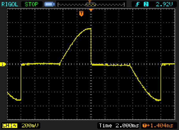
Figure 6A - Captured Trailing Edge Dimmer Waveform
The ideal is closely matched by reality. The current waveform shown above was captured using a trailing-edge dimmer, using a 75W incandescent lamp as the load. As you can see, the waveform is virtually identical to the theoretical (ideal) waveform shown above. The RMS current is 200mA. Measured fall time (from maximum to zero current) was about 30µs, but it is benign because this is the removal of voltage rather than the application of voltage - very, very different scenarios.
Figure 7 - Trailing Edge Dimmer Block Diagram
C1 and L1 are again the RF interference suppression components. The rectifier is needed because MOSFETs cannot switch AC, only DC. The power supply, zero crossing detector and timer are generally all part of an IC designed for the purpose. Waveforms are shown at each point of the circuit. The output of the zero crossing detector resets the timer, sending its output high, and thus turns on the MOSFET. After a time between zero and 10ms for 50Hz, the output of the timer goes low, the MOSFET switches off, and current through the load is interrupted.
In most respects, leading edge and trailing edge dimmers are exact opposites of each other.
Because the output voltage rises relatively slowly, the massive current spike that a leading edge dimmer causes into a capacitive load is no longer an issue, and some dimmable CFLs and LED lamps work perfectly ok with this kind of dimmer. However, trailing edge dimmers must never be used with iron core transformers, and this is always stated in the instructions.
Why? It would seem that the trailing edge dimmer should be fine, but the problem is largely due to the back-EMF that's generated when the switch turns off 100 or 120 times every second. The back-EMF energy cannot be dissipated, so builds to a potentially destructive voltage. In addition, turning on any inductive load at the zero crossing of the mains waveform results in a much higher than normal magnetising current. The most likely result will be that the dimmer will be damaged, either due to over-current or over-voltage. It is unlikely that commercial units will be able to handle the extra current or dissipate the back-EMF energy without severe overheating or destruction.
Back-EMF is generated in any inductive load, because the inductor is an energy storage (reactive) component. The energy is stored as a magnetic field, and when current is interrupted the magnetic field collapses, generating a current in the process. If there is no load (such as a lamp) connected to the inductive component, even a small current becomes a very high voltage. This effect is seen regularly, but is commonly dissipated as a small arc across the switch contacts. Such arcs are harmless if they only occur a few times a day, but if repeated 100 or 120 times a second the average power becomes significant, as does heat and the potential for fire.
Figure 8 - Trailing Edge Dimmer Schematic
As you can see, it's not easy to figure out how the circuit works when simply faced with a multi-pin IC. However, I've labelled the pin functions, and it is useful to see the schematic just to see some of what's been done. Note that the circuit shown is designed for a 3-wire connection, which is far more stable than the more common 2-wire dimmers. Naturally, this is not the only way, and some commercial trailing edge dimmers such as the one pictured below use one or more 555 timer ICs and a multiplicity of other surface mount parts to achieve the same end. However, nearly all commercial dimmers are only 2-wire and they often perform badly with electronic loads (CFL or LED lamps for example). The Atmel U2102B would be a good starting base for a proper 3-wire dimmer, but unfortunately it's now obsolete and I can find no equivalent. The circuit shown is adapted from the U2102B datasheet, but uses a MOSFET instead of the IGBT (insulated gate bipolar transistor) shown in the example circuit. See Figure 10A for an updated circuit (although the IC is not easy to get).
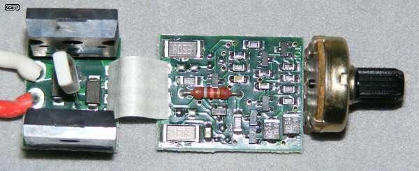
Figure 9 - Insides of a Commercial Trailing Edge Dimmer
The two large devices on the left board are power MOSFETs. Note that the underside of the PCB is also covered with parts, including the timer, another IC that cannot be identified, four transistors and several resistors and capacitors. While the unit pictured would be fairly cheap to manufacture, I imagine that perfecting the design for high reliability in normal use could have taken a great deal of time. At around AU$50 from my local hardware outlet, it's not cheap compared to the more common trailing edge dimmer (typically around $16 - $20, but some are much more).
Figure 10 - Measured Current Waveforms
The commercial trailing edge dimmer pictured was tested with a 60W incandescent lamp, and gave the waveforms shown above. While the maximum setting differs from the ideal waveform shown in Figure 5, when set for minimum (and up to about half power) theory and reality coincide very well. The circuit is unable to act as a true short circuit when fully on because some of the applied voltage is needed to power the electronics. This causes the discontinuity seen around the zero current region when the dimmer is set to maximum. Note that the above waveforms were captured when this article was first written in 2008, but are just as valid as the digital oscilloscope capture shown in Figure 6A.
Note that unless an electronic based lamp is specifically claimed to be dimmable, a 2-wire trailing edge dimmer will not work. Just for a test, I tried it with a normal CFL. There were no huge current spikes, but the lamp did not dim in a sensible or predictable manner, and the dimmer circuitry itself became confused and would not operate properly. This applies equally to CFL and LED lamps unless they claim to be dimmable in the instructions. Continued use of any electronic lamp with a dimmer may cause circuit damage, severe overheating or fire. As noted earlier, all dimmable electronic lighting products should only ever use 'universal' or trailing edge dimmers, even if the manufacturer claims that TRIAC based leading edge dimmers are permitted.
Figure 10A - FL5150 Leading/ Trailing Edge Dimmer
The above drawing is adapted from the Fairchild (now ON Semiconductor) datasheet for the FL5150MX dimmer IC. Only the 230V, 50Hz 3-wire version is shown, and the circuit above is modified from the versions shown in the original datasheet. Maximum output level is only available when the IC is used in 3-wire mode, and 2-wire mode is not recommended for any electronic load. The IC is available from a small number of outlets (one only at last look), but it hasn't been built or tested. Although shown with IRF840 MOSFETs, larger ones can be used for higher power. With the IRF840s in place, the maximum load is limited to around 1A (up to 230W, depending on the power factor of the load). For 60Hz operation, use the FL5160MX (the internal timers are different). These ICs are only available in SMD packages. Click Here for the datasheet.
There is also a complete schematic for a known working (i.e. built and tested) 3-wire trailing edge dimmer in the ESP project pages. See Project 157A for details.
Universal dimmers have inbuilt 'smart' functions that allow the dimmer to decide whether it should operate as leading or trailing edge. The detection circuitry is not always as smart as one might hope though, and they can sometimes make a wrong decision. Some home automation systems have switches that allow universal dimmers to be set to auto-detect, leading or trailing edge. The facility is usually not provided with small 'wall plate' dimmers though, so you have to rely on the dimmer making the right decision.
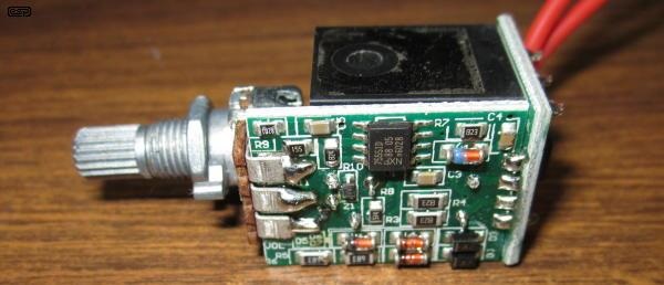
Figure 11 - Universal Dimmer Intestines
The inside of a fairly typical 'universal' wall plate dimmer is shown above. While one might expect that a small micro-controller might be used, it appears to be based on a dual 555 timer and a pair of MOSFETs. There are a few other passive components and several diodes, and that's basically all there is to it. These dimmers are generally suitable for dimmable electronic loads, but as noted, they don't always make the right decision. Like all 2-wire dimmers, they often don't perform well with electronic loads.
Tests so far show that it works acceptably well with some dimmable LED power supplies, and it goes without saying that performance with incandescent lamps is close to perfect. This particular unit was destined to drive 4 x 12W dimmable supplies for downlights that I've had for some time, but didn't use because the drivers were rubbish and were not dimmable.
It is important that universal dimmers aren't used with mixed loads, such as electronic transformers and iron-core transformers. Since the requirements for each are completely opposite, the dimmer can never select the correct mode. It will either fail or cause an external failure in connected equipment (or both).
In case you are interested, I'll describe the way that some (and perhaps most) universal dimmers decide whether they should operate as leading or trailing edge. If an inductive load is present, when the dimmer turns off under load there will be a high voltage spike generated. This is the same spike we tame with a diode when driving relays. The dimmer has a circuit to detect the spike, and if detected it will switch from trailing edge to leading edge mode. Inductive loads are quite happy with a leading edge dimmer, so the dimmer will remain in leading-edge mode after the circuit has detected spikes.
This process happens each time the circuit is turned on, because the dimmer has no memory so can't simply remember the setting it used last. Detection will normally happen very quickly - a few cycles of the mains at most, and when the voltage to the load is quite low. All trailing edge and universal dimmers I've seen have a 'soft start' feature, where the voltage to the load is developed over a few seconds. During this time, the dimmer will detect high voltage spikes caused by an inductive load, and will change to leading edge mode.
The process is covered by a patent - see A universal dimmer - EP 1961278 B1 granted to Clipsal Australia in 2012. I think it's a very clever application. It relies on using MOSFETs with a defined and guaranteed avalanche rating so they will not be destroyed by the spikes, but they are very common these days.
Both leading and trailing edge dimmers have exactly the same power factor for the same output power to the load. Neither type allows any real or useful method of power factor correction, and the only mitigating factor is that at low settings current is drawn from the mains during parts of the cycle that most small power supplies don't use. However, the power factor is still awful - especially at very low power settings. Despite this, there is no doubt that the power consumption is reduced in proportion - especially with LEDs. Power is also reduced with incandescent lamps, but not to anything like the same extent.
The 'on angle' column refers to the number of degrees of the waveform where power is delivered to the lamp. A full cycle is 360°, and each half cycle is 180°. Increments of 18° were used because at 50Hz, 18° equates to a 1 millisecond interval. This was used for ease of calculation for the table. These data are exactly the same for a 60Hz source, the only difference being that the time for one complete cycle at 60Hz is 16.67ms instead of 20ms. This does not affect the on-angle, power or power factor, but the current will be different because of the different voltage used by 60Hz countries.
| On Angle | Ideal Current | Ideal Power | Percent | Power Factor |
| 180° | 1000 mA | 230 W | 100 % | 1.00 |
| 162° | 994 mA | 227 W | 99 % | 0.99 |
| 144° | 971 mA | 217 W | 94 % | 0.97 |
| 126° | 918 mA | 194 W | 84 % | 0.92 |
| 108° | 829 mA | 158 W | 69 % | 0.83 |
| 90° | 702 mA | 113 W | 49 % | 0.70 |
| 72° | 557 mA | 71 W | 31 % | 0.55 |
| 54° | 391 mA | 35 W | 15 % | 0.39 |
| 36° | 226 mA | 11.7 W | 5.1 % | 0.23 |
| 18° | 83 mA | 1.6 W | 0.7 % | 0.08 |
| 0° | 0 | 0 | 0 | N/A |
Note that the load used for the above table is purely resistive (hence 'ideal' current and power), and remains constant at all settings. Incandescent lamps do not present a constant load though. As the filament runs cooler at low settings, its resistance is lower and it draws more current than expected. For this reason, although dimming unquestionably reduces the power used, it doesn't reduce it as far as one might expect (or hope).
A typical 100W GLS (general lighting service) lamp will be drawing around 18W when set for a dull glow - one would normally expect less. The filament resistance falls to around half the full power resistance because it's so much cooler, so twice as much current is drawn than would be the case for a fixed resistance. For reference, a 100W GLS bulb was tested, and measured 44 Ohms when cold and 552 Ohms when hot (at full power - 95.8W).
Many new installations using low voltage halogen lamps now utilise an electronic transformer. The traditional iron core transformer works well and will last forever, but they are expensive. Some are also built very much to a price, and are rather inefficient, wasting 20% or more of the total applied power as heat. Electronic transformers are usually much smaller and lighter, so tend to lack the 'solid quality' feel, but most are reasonably efficient, typically wasting well under 10% of the total power. Lower losses mean less heat and marginally lower power bills. Although the dissipation of each unit individually may seem reasonable, when thousands of them are running the extra loss becomes significant.
A conventional iron core transformer operates at the mains frequency (50 or 60Hz), and the core needs to be fairly large because of the low frequency. Core size is inversely proportional to frequency, so operating at high frequency means the transformer can be much smaller. The term 'electronic transformer' is really a misnomer - it is actually a switchmode power supply (SMPS). Electronic circuits are used to rectify the mains and convert the AC into pulsating DC. This pulsating DC is then fed to a high frequency switching circuit and a small transformer. Figure 10 shows a photo of a typical unit.
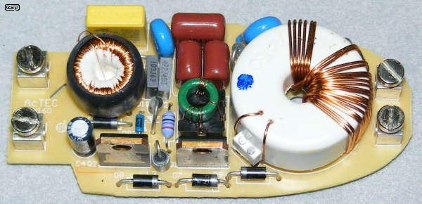
Figure 12 - Electronic Transformer Internals
The mains terminals are on the left, and the 12V output terminals are on the right. There is some RF filtering at the input, and the two switching transistors are the upright devices along the bottom edge. The little green ring is the transistor switching transformer (T1 in Figure 12), and the output transformer is the large white plastic object. This has a ferrite core with the primary windings on the inside, and the secondary (the 12V output) is wound on the outside of the plastic insulating cover.
The output is not rectified - it is AC, but comes in bursts of high frequency signal (see Figure 13 for the output waveform).
Figure 13 - Electronic Transformer Circuit Diagram
T1 is the transistor switching transformer. It has three windings, the primary (T1A), and two secondaries (T1B & C). Compare this with the green transformer in Figure 10. The primary is a single turn, and each transistor drive winding is 4 turns. T2 is the output transformer. DB1 is a DIAC (as used in the leading edge dimmer), and is used to start the circuit oscillating once the voltage exceeds about 30V. Once oscillation starts, it will continue until the voltage falls to near zero. Note that the base output frequency is twice the mains frequency, so an electronic transformer used at 50Hz actually has a 100Hz output frequency signal, which is made up of many high frequency switching cycles.
Most electronic transformers will not function with no (or light) loads. For example, a 60W unit will typically need a load that consumes at least 20W before it will function normally. With a very light load, there is insufficient current through the switching transformer's primary to sustain oscillation.
Figure 14 - Output Waveform of Electronic Transformer
Although the waveform shown is exactly as captured by my PC based oscilloscope, the transitions that are clearly visible are an artifact of the digitisation process - the frequency is much higher than indicated. The RMS voltage of the waveform shown measured 12.36V, but it is a difficult waveform to measure accurately. I expect that the actual voltage was closer to around 10V as measured using an analogue meter (the nameplate rating is 11.5V). Across a 2 ohm load (5A), output power was around 50W. The supply drew 231mA from the mains (52.2 VA). The measured input power was 52W, so power factor works out to be close enough to unity. Efficiency is almost 96% - a very respectable figure indeed.
Care must be exercised if using an electronic transformer with low voltage LED lamps or CFLs. Because these lamps have an internal rectifier, the diodes must be high speed types. Normal rectifier diodes will get extremely hot because the operating frequency is much higher than that for which ordinary diodes are designed. Although the waveform envelope is only 100Hz, the switching frequency is much higher - typically around 30-50kHz (frequency typically decreases with increasing load).
It has to be mentioned that the energy savings of electronic transformers may often be overstated. While conventional transformers will last virtually forever, electronic transformers can fail at any time, and prove this by doing so. The high temperatures encountered in the roof-space of many houses stresses the semiconductor devices, and the widespread use of lead-free solder ensures that solder joint failures are not uncommon. I've seen several failed units, and while I may be able to fix some of these, 99% of householders will simply throw a failed unit away and install a new one. When manufacturing, shipping and driving to the shops to get a new unit are all considered, you (and the environment) may well have been better off if an 'inefficient' iron-core transformer was used instead.
While many people (including me, 40-odd years ago) have experimented with DC dimmers, up until recently there has not been much call for them. There is the occasional time when a car lamp (spotlight or other) needs to be dimmed, and most cars have dimmable lighting for the dashboard. In the latter case, most commonly, a variable resistor is used in series with the lamps or in a few cases, different values resistors are switched in and out of circuit as needed.
While this is alright for low power systems with poor efficiency, there is no point making high efficiency lighting products and wasting power with a resistive dimmer. To show the waste power, a simple calculation can be done, assuming a simple 12V supply and a 12W lamp ...
| Lamp Power | Current | Voltage | Series Resistor | Resistor Power |
| 12 W | 1A | 12 | 0 | 0 |
| 9 W | 866 mA | 10.39 V | 1.86 Ohms | 1.4 W |
| 6 W | 707 mA | 8.48 V | 4.97 Ohms | 2.48 W |
| 3 W | 500 mA | 6.00 V | 12 Ohms | 3 W |
For simplicity, the lamp is assumed to have constant resistance, but this is not true for real filament lamps of any voltage and just makes the problem worse. This doesn't change the principle though, and including the lamp resistance for the different settings would just confuse the issue. Note that for 3W output, the (battery) current should be 250mA (ignoring losses), but with a resistive dimmer it's 500mA and 3W is dissipated in the resistor. Even if the light source were 100% efficient, the resistor has reduced this to 50%.
Clearly, this method cannot be used if we want maximum efficiency. While 3W doesn't sound like much heat, trying to dispose of it in a confined space is very difficult if high temperatures are a problem. The efficiency issue becomes far more important as lamp power is increased, and for flexibility a better solution is needed. Fortunately, there is a very simple answer. Pulse width modulation (PWM) is a common technique in electronics, and provides extremely high efficiency in the electronic circuits. By modulating the on-off periods of the voltage sent to the lamp, its brightness can be controlled easily with very low losses.
If the voltage is switched on and off with equal timing (50% mark-space ratio), the attached lamp (or high power LEDs) sees the full voltage (and full power) for half the time and hence the LEDs operate at ½ the power. Because the ratio can be changed from zero (fully off) to maximum (fully on) with a potentiometer or a 0-10V DC control voltage, this system is ideally suited to LEDs fed from a constant voltage power supply.
PWM systems can become confusing, because some have a filter at the output to remove the AC component of the waveform. If this is done, the average voltage is applied to the lamp. With 50% modulation, the lamp will receive 6V DC, and power is only 3W (¼ power). A filter cannot be used with LED lamps, because they are highly voltage dependent. If the voltage to a 12V LED array were reduced to 6V with a filtered PWM system, there would be no light output at all. The LEDs will not have enough voltage to overcome their forward voltage of ~3.3V. Most white LEDs have a forward voltage of about 3.1V up to 3.3V or more, and a 12V array will use 3 in series (9.9V), with the remaining 2.1V absorbed by the current limiting resistors.
Figure 15 - Pulse Width Modulation Waveforms for DC Dimmer
For dimming LED lamps, we don't use a filter, and the switching frequency can be kept low enough to minimise radio frequency interference. Around 300Hz works very well, and although the LEDs will switch fully on and off 300 times each second, our eyes cannot see the flicker rate as it is much too high. Lamp flicker is a hot topic in some areas, but provided it is well above the maximum visible rate there should be no problems. Normally, anything above 100 flashes/second is considered to be well above our persistence of vision threshold (many references are available on the Net). However ...
| Please Note: Although the flicker cannot be seen with the naked eye, care is needed
when a PWM dimmer is used in any industrial application. It is entirely possible that the flicker rate combined with rotating machinery can produce a 'stop
motion' effect due to the stroboscopic nature of pulsed light sources. PWM dimmers should not be used in LED fixtures in machine shops or near machinery
of any kind! This can be extremely dangerous under some conditions, because various machines can appear to be either stopped or only rotating slowly, when in fact they are spinning at normal speed. The danger is most extreme with machines like lathes, drill presses and milling machines, but the stop motion effect can make any rotating machine appear 'safe' when in reality it is anything but. This effect is sometimes apparent with fluorescent lamps, but PWM dimmed LED lights may be far worse in this respect. |
Not using any filter also maximises efficiency, but accentuates the possibility of strobing. In a typical switching DC dimmer, the power lost across the MOSFET will be less than 100mW with a 12V supply and a 10 Amp load if a robust MOSFET is used. The reference signal for a PWM system is usually a triangular waveform as shown (Figure 14, Red). This is compared against the control voltage (Blue), and if the control voltage is greater than the triangle wave the power MOSFET will turn on and power is applied to the load (Green). Likewise, if the triangle wave is greater than the control voltage, the MOSFET will turn off. Varying the control voltage changes the on-off ratio, and the power to the load.
Figure 16 - Block Diagram of DC Dimmer
This type of dimmer is certainly not new, and similar circuits are also used for DC motor speed controls. Its application to general purpose lighting is not yet common, but is likely to become so for low power systems. Because the circuitry is so simple and easy to control, it will likely become widespread as complete LED luminaires become popular. This is only a matter of time, since there is no requirement to be able to change the lamp because of the very long life of LEDs. Complete fittings suitable for household and commercial applications will not need replaceable lamps as we know them now, and with simple circuitry and full range (and virtually lossless) dimming capabilities will ultimately define the fittings of choice. The dimmer may be installed in the fitting (as part of the power supply), needing only a pair of low voltage wires to the control.
This also makes home automation systems easier to implement, because there will no longer be any need to modify the AC mains voltage - everything can be done at low voltage. The power supply module is easily made to consume very little power when no DC power is being used, so even the switch can be dispensed with. A test dimmer I built is quite capable of handling up to 120W (12V at 10A), but draws less than 20mA (less than ¼W) when set to minimum. The dissipation of the dimmer itself is typically around 3W or less at maximum power (almost all in the MOSFET), so it has better than 97% efficiency.
This dimmer is ideally suited for LED lamps. It allows total control from fully-off to fully-on, and a subsequent reduction of power when the LEDs are dimmed. As shown, this dimmer method is suited only to LED arrays that already have current limiting. The next stage for LED lamp control is to dispense with resistors for current limiting, and use PWM current limiting instead. PWM current limiting is already used with many lamps, especially the high power types, and it can be expected to become more common as LEDs become the lighting method of choice for most applications.
The ease with which the LEDs can be controlled makes this very attractive, and the high luminous efficacy that is currently being achieved (at up to 180 lumens/Watt and improving all the time) means more light with less power and very little heat.
Figure 17 - Typical 12V DC LED Array (Constant Voltage Source)
A typical LED array designed for 12V operation is shown above - 3 x 120 ohm resistors will normally be used because most arrays use surface mount resistors which are much lower power than traditional through-hole types. The 40 Ohm limiting resistors set the current through each LED string to 52.5mA, and the four strings are in parallel. The total current will be 210mA for a total power of 2.5W. The resistors are unfortunate, because they dissipate power but do no useful work. Each resistor dissipates about 37mW, so a total of 0.44W is wasted. This arrangement is very sensitive to voltage - an increase of only 0.5V will cause the LED current to rise to 65mA, and a fall of 0.5V will cause the current to fall to 40mA. While this is less than ideal, at present it is not economical to include individual high efficiency current regulators in place of the resistors. The abundance of medium and high power LEDs now makes small arrays such as that shown redundant.
Note that PWM dimming between the power supply and the LEDs is only possible if the LED array is powered from a constant voltage supply. Where constant current supplies are used, adding an external PWM circuit is likely to cause LED failure because the voltage will rise when the LEDs are turned off. When turned on again, the higher than normal voltage will cause excessive current and LED damage is inevitable. When constant current supplies are used, dimming is internal to the power supply. The PWM controller either switches the current regulator on and off or varies the output current.
Many LED arrays are now being made using matched LEDs, and they are wired directly in series/ parallel strings without any resistance at all. These arrays are invariably driven using a current regulated power supply, and are available in very high power modules. I've worked with 100W and 150W modules, but it's usually better to use a larger number of lower powered LED arrays because it's too hard to heatsink a module when the power dissipated is in the order of 100W or more.
Resistors are only used with low power LEDs, and most of the latest LED arrays use matched LEDs instead - even for relatively low power. Dedicated switchmode current regulator ICs are now common, and limit the current to the required value but dissipate almost no power. For higher power LEDs (1-100W types for example), active current limiting is used in virtually all quality lamps. Unknown branded stuff you might find in the supermarket or on online auction sites are a gamble, and even some of the major manufacturers have had serious problems with LED products.
It is commonly believed that the colour of 'white' LEDs will change if the current is reduced linearly, as opposed to using PWM. This is usually not true though, and it is not a requirement that PWM be used. Simply changing the steady-state current to obtain the required brightness generally works very well. While there is almost certainly some colour shift and/or change of colour rendering index (CRI), it's rarely a problem with modern LEDs. Dimmed LEDs not only reduce power consumption, but also reduce the heat generated by the LEDs themselves, so their life is extended. LEDs will also improve their efficacy (measured in lm/W) as current is reduced, because they operate at a lower temperature.
Lower temperature = longer life and greater light output for each watt supplied.
As LED lighting products mature, so too do the ICs needed to drive them. There are quite a few major manufacturers who are making LED driver ICs, and some of these include the ability to provide dimming - usually by gating the switch-mode current source on and off at several hundred Hertz (PWM). We are stuck with existing light fittings for the next few years because people generally prefer to simply change lamps rather than change the fitting for a dedicated LED luminaire. We are now seeing fittings that are designed specifically for LEDs, and have inbuilt power supplies (ballasts) and dimming facilities. These are complete luminaires, and do not rely on any form of interchangeable lamp. LED modules and power supplies can be replaced independently.
This is being done, but few standards currently exist so each manufacturer uses its own proprietary system. Although this is changing, relatively few lighting manufacturers seem willing to embrace the idea of using standardised light modules (commonly known as 'light engines'). The ability for manufacturers of luminaires to choose the optimum light engine from a variety of manufacturers is an ongoing process that's only just starting to make headway [3, 4] for example. Having multiple 'standardisation' bodies is not helpful. Official (government regulated) standards also exist in many countries.
Dimming performance (using current generation dimmers) is greatly improved if the power supply/ ballast is fully power factor corrected. This type of power supply acts more like a resistive load than simple capacitor input filter loads such as that shown in Figure 2 (Non-Linear). Many of the latest LED power supplies use power factor correction, but not all are dimmable.
Making fittings with features that are too complex or that don't meet the real needs of consumers will delay the uptake of LED lighting. Dimming remains one of the greatest obstacles, and many attempts have been made. Some work well enough (or at least to a limited degree) with existing dimmers as is the case with 'dimmable' CFLs, but the results are generally not very satisfactory. A large part of the problem is (again) that there are no standards, and people expect to be able to use existing dimmers - either leading or trailing edge 'phase cut' types.
What is needed is a dimming protocol that is compatible with existing wiring but that works properly and consistently, and there doesn't appear to be solution in sight at the moment. In general, it's not helpful to be told in an advertisement that "Wi-Fi controller bring you convenient life" (sic), when you know that the entire system is proprietary and if it fails you have nowhere else to go for replacements. The offer of "Different RGBW Four Channel Controller and Amplifier" is singularly pointless, especially if I don't know what it's compared to (it is 'different' after all). "2.4G Full Touching Controller: Nice Shape and Convenient application" speaks for itself - these are actual claims seen in an email I received as I was writing this section.
One simple protocol that would make sense is to go back to the old 0-10V standard (current sourced by the dimmable driver), and there are several LED luminaires that do just that. This allows single installations to use a variable resistor to change the voltage, so the 'dimmer' is just a 10k potentiometer in the wall-plate and little else. Unfortunately, most are not compatible with existing wiring though. For home automation systems, C-Bus and DALI already have 0-10V interface modules. By using a simple analogue control system, the cost is minimal for any type of installed system. If dimming isn't needed, the dimmer pins can simply be left disconnected. This arrangement even allows for multiple light fittings to be controlled from a single control, and the cost added to each fitting is minimal once they are in mass production. Some LED fixtures have an in-built DALI interface, although there are some claims that the appropriate standards are not always adhered to so performance is not guaranteed.
Unfortunately, even 0-10V has two different 'standards' - one where the dimmer provides current (IEC 60929) and the other (ANSI E1.3) where current is supplied from the power supply/ ballast. While it is commonly accepted that the 0-10V line should source or sink around 1mA, this isn't standardised either. To make matters worse, there is no fixed standard for the low voltage control wiring. No-one can be completely sure if it is classed as 'SELV' (safety extra low voltage) or should be considered 'live' along with the mains wiring. This determines the type of wiring needed from the power supply to the dimmer controller and the degree of separation needed between mains and control wiring. Almost always, a separate switched active is needed for the power supplies, because zero volts rarely means that the power supply will be turned off.
It would be useful if suppliers of ballasts/ power supplies that use 0-10V dimming to include a switch or jumper, so that one unit can be configured to source current (1mA or 10mA), and the remainder set so they simply sense the voltage level. This would allow the use of a simple 10k (1k for 10mA) potentiometer to set the voltage, and all connected units would work in unison. At present, the only way that 0-10V dimming can be done successfully is to use a powered 'dimmer module' that can supply or sink current as needed. Using a selection switch would allow a single 'master' 0-10V interface to control up to (say) 10 'slave' interfaces. Any unit that was disconnected would simply ramp up to full brightness.
It would be a big mistake to create new digital protocols just to ensure that people must purchase fittings and controls from a particular supplier. There are several luminaires that do exactly that, using an IR (infra-red) or RF (radio frequency) remote control similar to that used by home entertainment equipment. While convenient, standards are necessary so that remote controls are compatible. No-one would want the system we have with TV, set-top boxes, DVD players (etc.) where we commonly have multiple remotes, one for each item that needs to be controlled.
This approach will cause much FUD in the marketplace, and (apart from a few gimmick consumer products) has largely been avoided - so far. While digital systems (including those operated by a remote control) may well offer far greater flexibility (such as colour changing and other effects), the majority of householders won't want to be able to use their room lighting as a home disco. At present, most home owners don't even use dimmers, so trying to sell all-singing, all-dancing lighting fixtures will simply alienate people who are already baffled by the new technology. Does anyone really want their room lights to be red between 2:00PM and 2:30PM, then green until 4:30PM? No? I didn't think so. 
The industry as a whole will do itself a great disservice if LED fixtures do not afford the simplicity of operation that is inherent with traditional lighting. While the idea of a 'home disco' system will appeal to a few people initially, the novelty will wear off rather quickly. If the fittings do not afford simple operation with minimum fuss, they will ultimately fail dismally. So far, the vast majority of professional products I've seen and/or evaluated have avoided the gimmicks, bells and whistles, and just do the job they were designed for - most do it extremely well.
Even with 'top-shelf' commercial LED fittings, the 0-10V protocol is surprisingly common, and it's often used to provide "daylight harvesting". This uses a simple sensor to detect ambient light, and reduce the brightness of the LED fittings when the light level exceeds a preset threshold. Lamps can be controlled individually or in groups, and 0-10V light sensors make installation simple. There's no requirement for a central controller, digital control protocols or any fancy electronics, just a fixture with 0-10V dimming and a suitable sensor mounted where it can 'see' daylight.
It was noted above that the earliest dimmers were either variable resistors (rheostats), Variacs or (sometimes) magnetic amplifiers. We are now in an era where there are literally thousands of very unfriendly loads on the mains. Switchmode power supplies as used in PCs of all kinds, countless small switchmode 'plug-pack' (aka 'wall-wart') type supplies, compact fluorescent lamps, many LED lamps and hundreds of other products use them, and the vast majority cause mains waveform distortion. Individually they are never an issue, but when there are vast numbers the problem becomes serious and causes major issues with the mains distribution infrastructure.
Because of this, there are more and more regulations aimed at limiting the levels of harmonic distortion that power supplies can create. These ensure that the mains is reasonably 'clean' (minimum distortion) so that distribution transformers and generators can be used to their maximum ratings. Since most power utilities the world over seem to be very reluctant to replace ageing equipment, they want to get the maximum performance and life from what they already have.
|
| While it has been claimed elsewhere that a Variac dissipates a lot of heat (I won't provide a reference because it's wrong in all respects), this is false. The main thing that precludes the Variac from 'modern' systems is the weight and bulk of the transformer, and the mechanical complexities needed to drive it. A geared motor can't respond instantly, but electronics can. The Variac (or any variable voltage autotransformer) is as close to ideal as you can get in terms of efficiency and not affecting the mains waveform. This is pretty close to the 'perfect' sinewave dimmer, but not if you need rapid response (although 'flash' capability can be provided by switching). Modern sinewave dimmers are fully electronic, but details are hard to find. |
As shown in this article, phase-cut dimmers have a dreadful power factor at medium and low settings, and it is not feasible to correct it without considerable expense. They also generate large harmonic currents on the mains waveform and some (especially older TRIAC based home dimmers) can cause radio interference. So, dimmers as we know them are (or will be) on the way out, because they can't meet any of the new requirements that are coming into force. Going back to using Variacs is one way, but they are expensive and need a motor and gears to be able to be changed remotely or by automation systems. However, a Web search reveals that there are still people who use Variacs as dimmers because they eliminate all of the problems created by phase-cut dimmers.
The advance of modern electronics may well be the solution, because we can do things today that were unthinkable only a few years ago. One of these is a 'lossless' sinewave dimmer. While they are not yet mainstream, and small wall-plate designs haven't arrived yet (or not that I've been able to find), they are being used for theatre and other areas where large numbers of lights are used and need to be dimmed. The basic concept is shown below. While the concept is actually quite simple, the reality is somewhat different because of the filtering needed, and the nature of mains AC loads in general. Although shown using a MOSFET, it is largely the advent of IGBTs (insulated gate bipolar transistors) that has allowed this technology to be developed. IGBTs are very robust and have lower losses than MOSFETs - essential requirements for this application. The MOSFET approach is still viable for small (~200W or less) dimmers.
Figure 18 - Basic Concept Of A Sinewave Dimmer
The circuit shown uses the control circuit to switch the MOSFET (Switch) on and off very quickly. To reduce the mains voltage, the switch is open for longer, so current can't pass through the circuit. Sinewave dimmers use pulse-width modulation (PWM), in much the same way as Class-D power amplifiers. By turning the switch on and off at (say) 25kHz, the switching losses are minimal so the system can have high efficiency. While the concept is simple, execution is difficult and not inexpensive. High frequencies make the filter easier to implement, smaller and cheaper, but increase switching losses. The converse is also true.
The current is more-or-less a sinewave, and it will follow the current through the load. If the load has a good power factor, so does the sinewave dimmer. The composite load of a high power factor lamp and a sinewave dimmer is 'grid friendly' and won't annoy the electricity suppliers. The filter circuits that are used to remove the high frequency switching waveform must be very effective, or RF interference will be created that can cause problems elsewhere (radio and TV reception for example).
Note that the circuit shown is highly simplified, and is not usable in the form shown. Yes, the circuit will function, but it is not intended to be something for anyone to build, it's simply a means to demonstrate the underlying concept. 'Real' sinewave dimmers are considerably more complex, and finding a workable circuit on the Net is a challenge (to put it mildly). Predictably, manufacturers of sinewave dimmers aren't anxious to publish their schematics.
Although comparatively complex and expensive, sinewave dimmers have the great advantage that they can be used with any load that's normally connected to the mains. Motors of all kinds (but with great care to ensure they aren't overloaded at a reduced voltage), transformers (conventional or electronic) and even lamps that are not normally considered dimmable can be used (although only over a limited voltage range for most 'non-dimmable' loads). Some manufacturers have referred to their sinewave dimmers as being equivalent to an electronic transformer.
Without filtering, the waveform will look like the red trace in the following graph. The 50Hz signal was switched with a 50% duty cycle at 50kHz, and the filtered waveform is shown by the green trace. The mains input was 230V/ 50Hz, and the voltage across the dimmer and load are approximately equal (~115V across each).
Figure 19 - Sinewave Dimmer Waveforms
By varying the duty cycle, the output voltage across the load can be the full 230V (less some small losses), all the way down to zero. In reality it isn't feasible to get the duty cycle low enough for voltages much less than around 10V, because the PWM circuits will usually be somewhat unstable with a low on-time (e.g. less than ~200ns). For reference, the top right corner shows an expanded detail of the chopped waveform (50% duty-cycle).
At this stage, it's not possible to guess when sinewave dimmers will be coming to a hardware store near you. My guess is that you probably shouldn't hold your breath, because it's likely to take some time. However, when household dimmers using sinewave technology become available, then (and only then) will there be any reasonable chance of success and consistency when dimming retro-fit LED bulbs or other fittings using wall plate dimmers. My guess is that IC manufacturers will (eventually) most likely fabricate almost everything needed into a single chip, needing only a few passive parts and the main power switches to make a complete dimmer. At present, there does not appear to be any way that a sinewave dimmer could be built small enough to fit into a standard wall-plate.
I stated that a true sinewave dimmer is more complex than the simple conceptual circuit shown above, but how complex is 'complex'? See Figure 20 for the answer. Even the PWM logic block in itself is not trivial, but we also need to use not one, but four MOSFETs, plus all the ancillary circuitry and 'floating' MOSFET gate drive. It might be possible to use a simpler circuit, but it becomes very difficult to prevent destructive voltage or current spikes unless an active clamp circuit (Q3 and Q4) is used as shown in the drawing below.
Figure 20 - General Arrangement Of A Sinewave Dimmer
Now you can see for yourself why wall plate sinewave dimmers aren't feasible at this stage. Figure 20 shows a simplified circuit of a workable sinewave dimmer - there's a lot of switching devices, and isolated drive electronics are needed for the output MOSFETs or IGBTs. The above drawing shows small pulse transformers (T1 & T2), but there are also electronic equivalents that can do much the same thing. The important thing to understand is that the circuitry is vastly more complex than a conventional phase-cut dimmer, and until such time as all the logic and drive systems are integrated into a single IC there doesn't seem to be a way to make a 'small scale' version.
The unfiltered output waveform is still the same as shown in Figure 19.
Note that in both circuits shown, the power supply section has not been shown. A power supply is needed to power the PWM logic circuitry, and sinewave dimmers must be 3-wire - active, neutral and load, and earth/ ground as well for larger (stand-alone) units. Attempting to make a 2-wire sinewave dimmer is not possible because of the power demands of the circuitry, and even if it were possible it would make the sinewave dimmer just as susceptible to load variations (and as unreliable) as 'traditional' 2-wire dimmers in common use already.
In many respects, a sinewave dimmer is basically a form of Class-D power amplifier, but it uses the AC line directly rather than converting to DC first. Unless you are already familiar with the principles of Class-D amplifiers this probably won't help you very much, but if you do understand Class-D then you already have some info on how a sinewave dimmer works. The control signal that sets the lamp brightness (output voltage) is analogous to the audio input. The main difference is that a sinewave dimmer uses an AC supply rather than DC, and the supply voltage is a great deal higher (325V peaks rather than a more traditional ±70V DC for example). The two MOSFETs used back-to-back form an AC switching circuit - they pass (or block) the input regardless of polarity (see the ESP article on MOSFET Relays for more details about how these work).
The key to getting a PWM sinewave dimmer to work properly is in the MOSFET drive circuits, input and output filters, and an accurate determination of dead-time (a very short period where all MOSFETs are turned off). None of this is trivial. Inductance in the switched output causes large 'flyback' voltage spikes, and these either have to be absorbed (which increases losses dramatically) or returned to the system, which is difficult to achieve. Capacitors and resistors need to be 'pulse rated', because of very high peak current. Much as I'd like to be able to give readers a known working circuit, I'm afraid that it's not possible at present. I do have a simulation that works well and has low losses, but converting that into a working circuit is another matter altogether.
Dimming is a challenge, and it's a challenge that few manufacturers of household lighting products will readily admit to. Almost all dimmers work perfectly with resistive (incandescent) lamps, but performance is extremely variable with electronic loads. While LED ballast/ power supply makers may claim their product is 'dimmable', don't expect to find any useful information - anywhere! The problems are compounded by the fact that the vast majority of dimmers are 2-wire, and depend on the load to provide their reference for mains zero-crossing (which indicates that a half-cycle has ended).
Dimmers and power supplies are a collection of fairly complex electronics, and there is no guarantee that dimmer 'A' will work with ballast (power supply) 'B' or vice versa. There are no standards for dimmers or dimmable power supplies, and the whole problem is made much worse when customers insist on being able to use 'legacy' products that were designed for use with incandescent lamps. In some cases, dimmer 'A' might work perfectly with one power supply but the same supply fails dismally with a different dimmer - even one of comparable type. Likewise, dimmers are extremely variable, and may work fine with one type of power supply but fail with another. Flashing, flickering and general instability are all failures, because customers won't accept unstable lighting.
Until such time as standards are implemented that specify the inter-working of dimmers and power supplies the problem is unlikely to improve. Use of 0-10V is one method, but customers often don't like that because it means that additional wires need to be run and any existing dimmer(s) replaced by 0-10V modules. Automation systems (C-Bus, DALI) are not the answer, because they are expensive, and require extra hardware, wiring and commissioning that adds greatly to the cost of an installation. There is also a lack of 0-10V dimmable power supplies/ ballasts - they exist, but aren't especially common. Those you do find may not be compatible with dimmer controllers.
There is no simple answer at present, and until such time as there are standards in place to ensure interoperability between dimmers and ballasts/ power supplies the situation will not get better. In the meantime, when it comes to dimming any electronic lamp/fixture (LED or CFL), the only way to have a fighting chance is if you are willing to run your own tests. Some combinations will work, some will be unstable (flashing/ blinking especially at low settings) and others may be completely unsatisfactory. In some cases, you may find that there are no combinations that work, so both the power supply (or the entire fixture) and dimmer have to be changed.
Manufacturer's claims should be considered apocryphal at best, because you will rarely or never know the exact type of dimmer that was used for their 'compatibility' tests. If a manufacturer can provide both the power supply and the dimmer, that's likely to be better than buying each from different suppliers. During testing, I've found that a Variac is usually the best dimmer of all (it's a true sinewave dimmer), and can provide smooth dimming from as low as 1% up to maximum brightness. Tests with leading and trailing edge dimmers have shown results that vary from useless to barely passable to acceptable. None are as good as dimming an incandescent lamp, other than some dedicated 0-10V controls. As noted earlier, TRIAC (leading-edge) dimmers should never be used with electronic power supplies due to excessive repetitive peak current that will eventually cause failure of the dimmer and/or power supply. Interestingly, I have seen LED drivers that will only work properly with a leading edge dimmer, but as expected draw excessive peak current and can be expected to fail far earlier than one might hope for.
You must be willing to experiment. Don't expect to find a combination that will work flawlessly at first attempt, other than by sheer luck. LED fittings/ luminaires by themselves are not an issue - dimming ability is ultimately all down to the power supply and the dimmer. Sometimes you will find that the only way to get a satisfactory end result is to connect an incandescent lamp in parallel with the LED power supplies or dimmable CFLs - hardly an ideal situation. Other dimmer/ power supply combinations may prove to be unsatisfactory regardless of what you do.
Don't expect LED or CFL lamps or fittings to dim in the same way as an incandescent lamp. It's unrealistic, because an electronic power supply can't be expected to behave the same as a simple resistive filament. While LEDs are perfectly suited to dimming, it won't happen until manufacturers decide on standards that allow the power supplies to be linked and controlled by a simple analogue interface such as 0-10V or some similar (simple) protocol that doesn't require expensive add-on hardware. These are fairly common for commercial/ industrial applications, but not for domestic products.
This article was written in 2008, and as of late 2017 very little has changed. Lighting manufacturers still make fully sealed indoor luminaires that are totally unsuited for use with electronic lamps, most dimmers are still 2-wire, and little or nothing has been done to address the issues of dimmer and lamp compatibility. Combinations that work well together are difficult to find, and no mainstream manufacturer bothers to run tests and recommend a particular dimmer as being suitable for their lamps. Most (still) fail to recommend that only trailing-edge dimmers should be used, and imply that leading-edge types are suitable. This is rarely true.
Finally of course, we can but hope that wall-plate sinewave dimmers become available in the not-too-distant future, as this is the only technology that will provide some degree of certainty. Trailing edge dimmers can also work very well, but are predictable only if designed as 3-wire types, with a fixed neutral reference that ensures that the dimmer will function reliably. These are unfortunately very difficult to find in hardware or lighting outlets.
Main Index
Lamps & Energy Index