
|
|
| Elliott Sound Products | Transformers - The Variac™ |
 Main Index
Articles Index Main Index
Articles Index
|
The term 'Variac' (from 'vary AC') has become generic, and commonly refers to any continuously variable autotransformer. Variac is a trade name, and has changed ownership several times since early 1930s when the device was first produced. Other trade names include Powerstat and Dimmerstat, and I'm sure there are many others. Some manufacturers simply call their versions 'variable voltage transformers'. The trade name Variac has been owned or licensed by Warburton Franki (in Australia), General Radio (Genrad), Claude Lyons, Statco and probably a few others as well. I shall use the term Variac in its generic form - this does not imply that variable transformers with the Variac branding are more desirable than others, only that I'm used to the term having used it all my working life.
The Variac is a special type of transformer, generally having a single winding and a single layer. The top section of the winding is flattened and machined to remove the insulation and provide a smooth surface for the sliding brush that's used to select the voltage needed. Some variations use a roller instead of a brush, but there seems to be no specific advantage. I still have my first Variac (branded as such) that I bought sometime around 1960, and it's been dismantled for service once in all that time - see Figure 1a. Figure 1b is a Matsunaga 1kVA Variac - made in Japan especially for use in Australia. It is described as a 'Deluxe Slide Regulator' (sic).
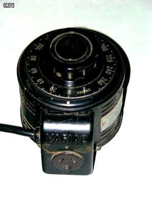

Figure 1a - Original 50+ Year Old Variac, 1b - More recent Bench Type
Other (low voltage) versions use a separate secondary, but still wound in such a way that a brush can make contact with the secondary windings. A photo of one that I have is shown below, in Figure 2a. Isolated secondary versions are rather uncommon, and I don't know of any manufacturer who still makes them. The one shown is very old, and as is obvious was made by Carl Zeiss (usually associated with precision optical instruments). I've had it for years, but it still gets used almost daily. Output is zero to 15V at up to 8.5A continuous, with a maximum rating of 120VA.
The little Powerstat unit is 120V (and 60Hz), so is of limited use in a 230V country like Australia. It's still potentially useful of course, once I find a use for it. 


Figure 2a - Carl Zeiss Variable Voltage Transformer, 2b - Powerstat Panel Mount
The traditional Variac is an autotransformer, and provides no isolation between primary and secondary. There can be no isolation, because there is only one winding. The brush (or roller in some designs) allows the user to select any voltage within the range, which generally extends from zero to 120% of applied mains voltage. Isolated versions do exist, but are uncommon. It's generally easier and cheaper to use a separate isolation transformer if full isolation from the mains is needed.
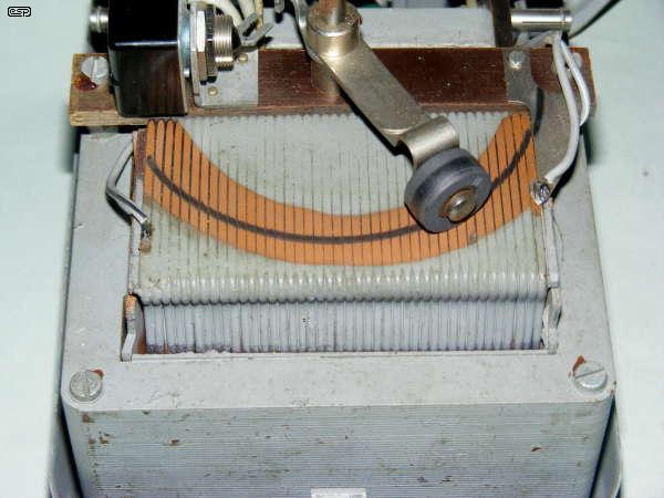
Figure 3 - Variable Secondary & Roller Brush
Figure 3 shows the secondary of the Carl Zeiss 'transformator', with the roller brush. There are also a few additions that I included to make it more useful as a workshop tool (hence the extra wires). Note the toggle switch. This is activated by the end of the wiper arm when the voltage is set to minimum, and is the main on/off switch.
In all, I now have six Variacs, ranging from the little 270VA Powerstat right up to a 6kVA monster. Not all of them get used regularly, but all are functional and get used when needed. I must admit that I don't often need the 6kVA unit, but I did get it very cheaply at the time.
Variacs were probably the first transformer to use a true toroidal core, wound with one continuous strip of suitable steel. It seems probable that early units would have been hand-wound, since it is important that every turn is perfectly aligned with the previous turn. While machines can do this, toroidal winders are a relatively recent invention. It is unlikely that early machines would have had the accuracy needed to lay the turns perfectly side-by-side for the full width of the winding.
A variable voltage transformer can be thought of in several different ways. Because it has a copper winding wrapped around a steel core, it is an inductor. As the tapping point is changed, it could (mistakenly) be considered as an inductive voltage divider. This is a gross over-simplification though, because that does not account for the genuine transformer action that occurs. Because the winding is tapped, it is an autotransformer, and this is the way it is usually considered. This is entirely correct, because the input current is reduced by the effective turns ratio between the primary (the full winding) and the 'secondary' - that part of the winding that is used for the output voltage.
If the tap is set for 50%, the input current will be half the output current (ignoring losses). One important thing about a Variac is that the maximum current rating really is the maximum. For example, the small Powerstat shown in the photo (Figure 3) is rated at 120V and 2.25 Amps - 270VA. A traditional 270VA transformer with a 60V output would be able to supply 4.5A, but that does not apply to variable transformers. The single winding is the same diameter wire from end to end, so the maximum current at any voltage is 2.25A.
Unlike any normal transformer, a Variac can be used with DC, although it is nothing more than a 'rheostat' or variable resistor. Needless to say, there is no transformer action, and usefulness is severely limited (to the point of being a pointless exercise at best). Not recommended, but interesting.
Many of the cheaper variable transformers available today are made in China. There's nothing wrong with them, except that they generally have a fuse fitted - in series with the mains input. When set to a low voltage (say 20V or so), the input current is only a fraction of the output current, so it's very easy to overload them, burning windings and the brush.
A 230V 3A transformer set to 20V can provide 34A without stressing an input fuse, but the transformer is meanwhile cooking itself, and will be destroyed if such abuse lasts more than a few seconds. Nothing wrong with an input fuse, but only if an output fuse of the same rating is also fitted. Short-term overloads are permitted for most Variacs, but are limited by the brush dissipation. The degree of permissible overload varies, so manufacturer recommendations should be followed closely to prevent damage.
One of the things that can be hard to find is the maker's specifications for overload limits. While not 'official' figures for all units, Statco states (depending on the model) that the time limit is less than 1 second at ×10, 12s at ×5 rating, 1 minute at ×3.5, and 20 minutes at ×2 the rated current. If subjected to an overload, the unit must be allowed to cool back to ambient temperature before use again (other than if use continues at lower current - less than 50%). In general, overloads should be avoided if possible, especially to protect the graphite brush (which may be hard to replace).
Off Time = On Time × (( Overload Current / Rated Current ) ² - 1 )
Off Time = 2s × (( 10 / 2 ) ² -1 ) = 49s
Using the above formula (from Statco), assume that you applied a 10A load to a 2A Variac for 2 seconds. You need to wait for 49 seconds for the brush and windings to return to a safe temperature before using it at rated load. If used at a load less than 10% of maximum, you can carry on regardless, as the system will still be able to cool down. If the formula provides an answer of one or less, then continuous operation is indicated. However, this is only (at best) a guide, as a lot depends on the ventilation of the unit.
Most Variacs that are fused have the fuse at the input. This is the worst possible place for it, as it doesn't protect the winding and brush from excessive current at low voltages. There should be an input fuse, usually slow-blow because of inrush current (Variacs are toroidal and have a fairly high inrush current). The secondary fuse will often be slow-blow as well, rated for the maximum allowable output current. A 500VA Variac can provide an output of a bit over 2A (230V input), so a 3.16A output fuse is close to ideal - this allows for some overload, and it is the responsibility of the operator to monitor the output voltage and current in use.
Figure 4 - Schematic of a Variac & Brush Detail
The schematic is fairly typical of most Variac type transformers. It is common to provide an additional number of turns to allow the voltage to be increased from the nominal. The amount of step-up varies with different makers, and can range from an additional 10% to as much as 20%. This allows the Variac to correct for low mains voltages, especially with units that are motor driven and used for mains voltage regulation.
The sliding brush deserves special comment. It is almost invariably made from carbon, in the form of graphite. The brush commonly spans at least two turns, and sometimes more. The small Powerstat unit's brush can span three turns. It would seem that if the brush spans two or more turns, it should form shorted turns, causing huge current flow and causing the transformer to burn out.
Fortunately, graphite is an anisotropic material, having very different resistivity depending on the direction of current vs. the alignment of the graphite planes [1]. A direct measurement across the brush of the Powerstat transformer gives a resistance of about 6 ohms, but this is reduced to ~1.5 ohms in the plane that joins the winding to the wiper arm. This means that each winding is basically feeding a resistor network that limits the maximum 'shorted turn' current to a harmless level. The resistor 'network' also helps average the voltage between turns, so instead of voltage steps, the output is more or less continuously variable.
The variation of resistance between the transverse (across the brush) and longitudinal (windings to wiper arm) directions depends on the specific graphite compound, and can range from 1:1 to as much as 10:1 respectively. It can be higher, but this makes the graphite compound too brittle, so it may shear during use. In Figure 4, I showed the variation as 5:1 as a 'typical' value. The different resistance ratios depend on the 'ordering' of the hexagonal graphite planes (particles) in the finished product. If all planes are in completely random order, resistance variation is 1:1
An alternative method used in Peschel® variable transformers is to use diodes to isolate metallic wipers [2]. Each wiper can only be allowed to touch one turn at any time, so two are used, joined by a diode network to prevent shorted turns. The voltage between turns is typically fairly small, but varies with the size of the Variac. Large transformers will have fewer windings (turns per Volt), with some having perhaps only one turn per Volt, so the inter-turn voltage will be one Volt. This is always a compromise, because if the inter-turn voltage is too high, the brush needs more resistance to prevent high circulating current. It's preferable to use more turns of thinner wire, and this is the approach commonly used in (probably) all Variacs on the market. The 270VA Powerstat has about 610 turns in total, or about 4.6 turns per volt. The inter-turn voltage is therefore only a little over 200mV - even a very low value resistance will prevent excess current flow across the brush.
Most Variacs seem to be wound using about 2 turns per Volt, so the inter-turn voltage is limited to 0.5V. This means that a typical 230V Variac will have at least 460 turns. There are exceptions - the 270VA and 6kVA Powerstat units are good examples, with 4.6 and 1 TPV respectively.

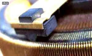
Figure 5a - Dimmerstat Brush, Figure 5b - Powerstat Brush
As seen above, the geometry of brushes varies widely. While some are very simple, others are shaped to fit into a spring-loaded wiper arm. Note the small pivot point used in the Powerstat spring arm - this presses on the centre of the brush, and allows it to move if the winding surface is less than perfect. There are probably as many brush shapes as there are manufacturers of variable transformers.
There are also a few mains output isolated Variacs on the market. These use a separate winding for the secondary, but use the same number of turns as the primary. The primary is wound first, then insulated and/or encapsulated to provide the perfectly level working surface needed for the winding contacted by the brush.
The brush resistance is also non-linear. If measured with an ohmmeter, it may show 20 Ohms or more, but when subjected to load current, this typically drops to less than 1 ohm. Needless to say, any voltage lost in the brush itself is dissipated as heat, depending on the current. At around 5A, we would expect the brush resistance to be no more than perhaps 0.2 Ohm, resulting in a voltage loss of 1V. This is still 5W lost as heat, which must be dissipated by the windings and brush mounting. Some Chinese Variacs use a heatsink for the brush. I don't own one, so it's hard to know if it does anything useful or is intended only to instil some degree of confidence in the buyer. Overall, it's probably not a bad idea.
I've mentioned the 6kW Variac that I have, so only thought it reasonable that some pictures be shown. This unit used to be a section of a 3-phase variable transformer (made by Superior Electric Co., who own the Powerstat brand name). Because it had no knob, one was fabricated from a piece of thick plastic. The DC resistance of the winding is about 0.5 Ohm, and the transformer has ~270 turns from end to end. The voltage between adjacent turns is just over one volt (confirmed by measurement). Voltage range with 240V input is from zero to almost 280V - somewhat more than normal. It also has tappings for both 230V and 115V input voltages. With 240V applied, magnetising current is 1.8A, much higher than I had expected. The transformer is quite obviously wound for 60Hz.
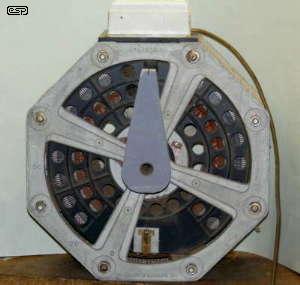
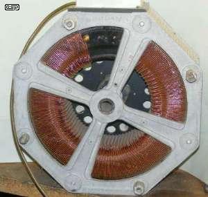
Figure 6a - 6kW Powerstat Front, Figure 6b - Powerstat Rear
Photos don't do this Variac justice of course - it weighs about 30kg, and to say that it's hard to move around is putting it mildly. It's fitted with a normal Aussie mains lead and a dual switched GPO (general purpose outlet) provides output connections. By default, the terminations are large bolts and nuts. Rather than using an arm to support the brush, the brush support is a large Bakelite disc, with holes to allow airflow through the whole transformer. This is clearly visible below. The brush can span a maximum of two turns - any more would cause problems because of the relatively high inter-turn voltage (1V).
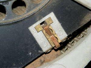
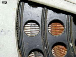
Figure 7a - Brush Detail, Figure 7b - Winding Detail
This is probably the most under-utilised in-service Variac I have, because few applications stress the 5A unit I normally use. It sits under my workbench, and can be used without having to move it ... provided the unit being tested doesn't require the voltage to be applied gradually while watching for problems. I had thought of adding a servo-motor and control system to it to allow me to maintain an exact voltage for the workbench, but it never got further than a thought experiment.
A Variac is an indispensable workshop tool. Apart from allowing you to increase the voltage to a newly built or repaired amplifier slowly to allow you to see any anomalies before they can cause further damage, there are many other uses as well. A fully variable power supply is easily made, by using a Variac and a normal transformer, bridge and filter caps. Any desired voltage is attainable, and it can be varied from zero to the maximum.
Using a Variac also lets you test equipment over the full mains voltage range that may be expected in the field. While we tend to think of the mains as being reasonably close to the claimed voltage (120V, 230V, etc), it can vary widely, especially in remote areas. A piece of equipment that is rated for a nominal 230V should work normally without failure at anything up to 265V in some parts of Australia (as well as many other countries). Likewise, the equipment should continue to work if the voltage is lower than nominal, and I expect any 230V gear to work normally with 200V mains. At this voltage, regulators should keep regulating, DC offset should remain within specifications, and no malfunction should occur. Some equipment will pass this test easily, but some will become unusable for a variety of reasons.
Power delivered to non-temperature-controlled soldering irons can be varied, as can anything else within the Variac's ratings. This includes brush motors as used in power tools, vacuum cleaners and the like. While induction motors can also be used with a Variac, this is not recommended - it is easy to burn out the motor (and/or the Variac) if you don't know what you are doing. Small shaded pole motors (as commonly used for desk and floor fans) can be controlled easily, and a Variac can provide continuously variable speed, unlike the push-buttons usually provided.
Variacs are also sometimes used with a servo-motor, to provide a regulated AC supply. Should the mains voltage change, the motor resets the Variac to restore the preset voltage. While very good with slowly varying mains voltage, they cannot react quickly if there is a sudden change. Some years ago, large DC power supplies often used a Variac coupled to a pot. The Variac's output was set so that the unregulated DC was just a little higher than the regulated voltage. This minimises the voltage lost across the regulator, so increases overall efficiency and reduces the amount of heatsink needed for a high-current supply.
Variacs have also been used as dimmers, and for stage lighting can be remotely controlled using a servo motor. They are very efficient, silent, and generate zero mains harmonics or filament 'singing' - unlike TRIAC dimmers. Dimming range is from zero to maximum, with no jumps or glitches in light output as the voltage is changed. Care is needed to ensure that the Variac's current rating is not exceeded at low brightness settings, where filament resistance is much lower than normal.
Variacs are also very common in process control systems, and can be used for motor speed control, heaters, and anywhere else that a high reliability, high efficiency and low maintenance variable AC supply is needed. Hot-wire plastic foam cutters are a prime candidate, and I regularly use the Carl Zeiss unit shown above for just that (as well as powering a battery drill whose battery died years ago). One of the modifications I made to this unit was to fit a 35A bridge rectifier internally, so I can get a variable DC output.
Safety
Any non-isolated Variac must be considered to be as dangerous as the mains itself, regardless of the output voltage at the time. Because there is always a risk that active and neutral could be reversed, no part of the output of a Variac can be considered safe unless it is stated to be isolated (and tested to verify that this is the case). Since the vast majority of all Variacs sold are non-isolated, the output must therefore be considered to be live.
For this reason, any Variac should be fitted with an earthed input lead with a normal mains plug. The output must likewise be connected to a mains socket, and all wiring enclosed. Some are supplied like this, while others are 'panel mounting', meaning that the user is expected to use the Variac as a fixed component within an appliance, and wire the output either to an approved receptacle or to another fixed appliance that uses the variable mains voltage obtained.
On no account should a non-enclosed Variac be used as a bench tool with leads hanging off the terminal block. This is an inherently lethal way to use it, and cannot be discouraged strongly enough.

| Note: With some Variacs, the shaft may not be isolated from the wiper. While unusual, the Carl Zeiss version is an example of a non-isolated shaft. In this case it's perfectly safe, because the secondary is isolated and low voltage. This may not always be the situation though, so before working on a Variac with the knob removed, please ensure that the shaft is isolated from all internal wiring. It's not always easy to see whether insulation is present or not, so a check with a meter is advised. |
That the Variac is a useful and necessary tool is shown by the range and ready availability of them in the market. One large UK supplier has no less than 34 different models available, and they are even available from many hobbyist electronics retailers. A web search will produce an astonishing number of results, but naturally not all are useful.
Large commercially available 3-phase models can be rated at up to many kVA, even up to 1MVA or more - very serious power indeed. For most laboratory or service work, a Variac of around 1kVA is the most useful. Smaller units are too limiting, and although I managed for many years with a 500VA Variac, it really is too small to be useful with large power amplifiers that are now common.
In general, the performance of a Variac is not often a major concern. Regulation may be important, but if the voltage changes with load, it can always be increased to compensate (a manual regulation system). When the Variac is set for the nominal supply voltage, the only impediment is the brush and resistance of the power leads. Figure 8 shows the typical regulation of a Variac [3].
Figure 8 - Typical Variac Regulation
The regulation is worst at 50%, because there is the maximum amount of wire resistance in circuit with the current. Current in the lower half of the winding is the same as that across the upper half, but is 180° out of phase (output voltage is in phase with the input). When set for 1:1 output, the winding current is only the magnetising current, as there is no transformation. Leakage inductance, which is generally quite high, also affects the regulation to a small degree. The biggest limitation is the maximum output current. For long-term reliability, the current rating stated on the nameplate should not be exceeded, regardless of output voltage.
Unlike a traditional transformer, the VA rating is of minimal use to you. Just because the output voltage is set for one tenth of the input voltage, this does not mean that the current can be 10 times that stated in the specifications. A 2A Variac can safely supply 2A at any voltage at or below the mains voltage (100% setting). This is in contrast to a conventional transformer, where a 10:1 voltage reduction means a 1:10 allowable output current. If used in over voltage mode where the output voltage is greater than the mains (e.g. 120% setting), then the VA rating must not be exceeded. A Variac used at the 120% setting can output a maximum of about 0.83 of the rated current. Assume a 1kVA, 230V Variac ...
Current = VA / Voltage
Current = 1,000 / 230 = 4.35A - Maximum continuous current for any voltage at or below 230V
Current = 1,000 / 276 = 3.62A - Maximum continuous current at 120% of input voltage
Other percentages can be calculated by the same technique. A brief overload is usually permissible, but the brush in particular is the main limitation. A short period at up to 10 times the rated current (inrush current into a high power amplifier for example) will probably not cause any major local heating, but you will often find that the brush seems to stick in position, requiring a bit of extra effort to move the knob after the overload.
If a Variac is used with a bit of care, it should have an indefinite life. As noted above, my 2A Variac is over 50 years old, and I have serviced it once in all that time. It still works as well as the day I bought it, despite a few abuses along the way. However, it has never been used for long periods in excess of its ratings, but it has been subjected to the occasional brief overload. As with all transformers, overloads are permissible, provided their duration is limited and time is allowed for the Variac to cool (especially the brush). If operated at 150% of rated current, a typical Variac can be used for a maximum of about 15 minutes, after which it must be allowed to cool to ambient temperature before the overload is repeated. In general however, overloads should be avoided.
One of the most common complaints about Variacs is catastrophic failure. Such complaints can be found on newsgroups and forum sites when Variac problems are discussed. Almost invariably, the failure can be traced to the user failing to understand that the rated current cannot be exceeded safely, regardless of output voltage. If a fuse or circuit breaker is used (highly recommended), it should be in series with the output, not the input. A second fuse in the input circuit is also a good idea, especially if the Variac is used to boost the mains voltage (over voltage mode). Slow-blow fuses of approximately the Variac's maximum current rating should be used.
If a Variac is likely to be used by inexperienced people (not a good idea at all), it would be worthwhile to add a thermal switch, attached to the winding with a suitable epoxy resin. Because the lowest voltages are the most likely to be abused, the thermal cutout should be mounted as close to the zero voltage (common) end of the winding as possible.
Circuit Specialists - Need a Variac? You can get one here. No affiliation - just an exchange link for anyone interested.
| Main Index
Articles Index
|