

|
| Elliott Sound Products | Sinewave Oscillators |
 Main Index
 Articles Index
Audio oscillators (aka audio signal generators) have been an essential piece of test gear for many decades. While laboratory instruments were available (at laboratory prices) from the very early days, it wasn't until the late 1950s that affordable signal generators became available for hobbyists. Most were still frighteningly expensive and of mediocre performance by modern standards, but there has been a ready supply of such instruments for professionals and hobbyists alike for many years now. Kit versions have been made by many different companies and 'hobby' circuits have been published in electronics magazines for as long as I can remember.
An intriguing conundrum on the Net is the constant belly-aching from many vested interests that "sinewaves are simple", and are therefore a poor test of an amplifier's distortion performance. If this were true, then a low distortion sinewave oscillator would not pose any problems to build, indeed, it too would be 'simple'. This being the case, I challenge those who believe this nonsense to build a simple variable frequency sinewave generator with minimal (or no) distortion. It's simple, isn't it?
Alas, this is not the case, and there are many different schemes published that desperately attempt to obtain a low distortion sinewave, without having to revert to complex high-bitrate digital synthesis, and without using the venerable (and now unobtainable) R53/ RA53 or similar NTC thermistor. Even a sinewave generator that has low distortion at one or two spot frequencies isn't easy, and a variable generator takes the difficulty to another level. Ideally, a high purity sinewave generator will not require tuned filters at the output to reduce distortion.
In this article, I will concentrate on variable frequency oscillators, because while spot frequencies can be useful if you only need to check distortion at a couple of frequencies, most people like to be able to test filters, amplifiers, loudspeakers, and other devices that are generally expected to be able to reproduce more than one (or two) frequencies. However, there are many requirements for single-frequency sinewave oscillators, so they are not avoided altogether.
The distortion should ideally be as low as possible, but anything below 0.1% starts to become rather difficult with many of the methods available. It's certainly possible to improve on this, but very careful adjustment of all the parameters (time constants, allowable stabilisation range, etc.) is needed to get good results. Some comparatively simple arrangements can give very good results, but only over a limited range (using common and readily available opamps). Indeed, opamps impose many additional limitations. Distortion is usually well within acceptable limits, but not many low-cost opamps will allow operation of any oscillator topology to much beyond ~30kHz. This is very limiting, as it is common for general purpose audio oscillators to have a range up to at least 100kHz, preferably more.
Note that this article is very specific - it deals only with 'linear' oscillators - those that are designed to generate a sinewave. Even more specifically, the range is limited to audio frequencies, plus at least a couple of octaves either side. Most audio oscillators are expected to be able to cover the range from about 5Hz up to at least 100kHz.
You won't find any multivibrators or other square/rectangle generators here, nor will you find RF oscillators, other than by a glancing reference.
Note that the schematics presented here are for the purpose of illustration and education, and should not be considered to be fully functional as shown. In many cases the circuits will work as described, but this is not guaranteed and cannot be assumed. Some circuits incorporating feedback stabilisation loops using other than lamps or thermistors may require some effort to ensure stability under actual operating conditions. This is an article that describes the principles - it is not a collection of projects that have been built and fully debugged.
No descriptions are provided for common function generator ICs. Basic function generators have been around for some time now, and there are several specialised ICs designed for just that purpose. However, most have mediocre distortion performance (typically around 1% for the better versions), and that limits their usefulness. Some of the ICs include the Exar XR2206, Maxim MAX038 and Intersil ICL8038, but not all are still available because they are now obsolete. If you are interested, look up the details for them - provided you don't need low distortion, one of them may be just what you need. Most use 'waveform shaping' to get a passable facsimile of a sinewave (see Section 7 - Waveform Shaping for an example). Several low cost function generators are available on-line, and most use one of the common ICs. You'll also see many DDS function generators at fairly low cost. None of the cheap function generators are suitable if low distortion is needed.
Note that power supplies and bypass capacitors are not shown in the drawings that follow. Most of the opamp circuits in this article will require ±12-15V DC supplies. Although all gain blocks are shown as opamps, in many cases you will have to build a discrete 'opamp' or the circuit will not be satisfactory at high frequencies. Most IC opamps will typically be ok up to perhaps 30kHz or so, but if you need good performance up to 100kHz or more, you'll almost always need a discrete circuit or a very fast opamp. All opamps (whether IC or discrete) need ceramic power supply bypass caps close to the IC or other parts to prevent instability (either parasitic or continuous RF oscillation). Discrete opamps may be needed if a lamp is used for stabilisation, because the current needed is high enough to cause many opamps to increase their distortion beyond the quoted figures.
An oscillator has two very specific requirements. The amplifier must be able to perfectly match the losses in the frequency determining network. The frequency determining network must be arranged so that the signal fed back to the amplifier results in positive feedback. If the gain exceeds that required for oscillation, the output will increase until it's distorted, and if too low the oscillation will die away to nothing. These constraints apply to all analogue oscillators.
By definition, oscillators do not require an externally applied input signal, but instead use part of the output signal via a frequency selective feedback network as the input signal. It is the circuit noise and/ or offset voltage that provides the initial 'trigger' signal to the circuit when positive feedback is employed. If the gain criterion is satisfied, the output builds up over a period of time, oscillating at the frequency set by the circuit components [ 9 ].

Note: The capacitors in frequency networks will typically be MKP (polypropylene) caps for high performance, or MKT (polyester) for a general purpose unit. 1% metal film resistors are recommended in all cases. Polypropylene is probably one of the better options where you need high stability. Never use multilayer ceramic caps in any oscillator unless you actually want it to have high distortion and very poor (and unpredictable) frequency stability with temperature variations (this isn't a common requirement in my experience). Polyester (PET, Mylar, etc.) caps have a positive temperature coefficient, and polypropylene is negative (but smaller). Polystyrene caps are very good in this role, but they are hard to get and are only available in fairly low values.
There is a very low distortion sinewave generator published as Project 174 that you may find useful if you need to build an audio oscillator. It uses a novel sample-and-hold circuit to achieve amplitude stabilisation, and distortion+noise is around 0.001% with good opamps. The oscillator circuit is the same as that shown in Figure 5, and amplitude control uses an LED/ LDR optocoupler. Another is Project 179, which uses a discrete circuit and a lamp with a 'padding' network to minimise the lamp induced distortion (particularly at low frequencies).
Many early sinewave oscillators used a dual variable capacitor for tuning. This is a good option, but it means that all resistor values are high to very high, which affects noise performance and makes the circuitry susceptible to stray capacitance. This option has not been included in any of the circuits shown, but can be used if you have a suitable dual tuning capacitor available. A significant advantage is that variable capacitors tend not to become noisy like potentiometers, and their tracking is usually better. The minimises amplitude 'bounce' as the frequency is changed. Given that you'll be hard-pressed to find a tuning gang of more than 500pF or so, that means resistors have to be 20MΩ just to get down to 16Hz. Such high values also increase thermal noise from the resistors themselves, but this isn't as much of a problem as you may expect.
I mention this first because many people will be tempted by cheap DDS modules that are available from many on-line suppliers. These look like a good idea at first, but you'll almost certainly become annoyed rather quickly because they are nowhere near as good as the specifications seem to indicate, and they generally have fairly poor distortion performance. An analogue circuit (and interface) will always be easier to use. Frequency and level accuracy of analogue circuits may appear poor, but mostly we don't care too much about absolute accuracy.
Many of the latest and greatest oscillators use DDS - direct digital synthesis, but such units are usually quite expensive. There are some very cheap ones, but they are not suitable for serious measurements. Even a 12-bit output is barely acceptable, as this will cause the minimum distortion to be around 0.04% - not bad, but certainly not very impressive. Lower resolution means higher distortion - 8 bit resolution gives a theoretical 0.5% THD with basic sample-rate filtering, and anything less than 8 bits is obviously pointless. While this can be improved with more advanced filtering, this increases complexity. For a usable system, I would not be happy with anything less than 14 bits, and preferably 20 bits or more. Needless to say, the digital clock frequency needs to be far greater than the highest output frequency. Distortion of a digitally generated sinewave with only sample-rate filtering falls by 6dB for each additional bit (the distortion is halved), so if we start from 7 bits (1%), 8 bits is 0.5%, 10 bits is 0.125%, etc.
Unlike a digital audio format, very steep low pass filters (to remove the switching waveform) usually cannot be used with test equipment. This isn't because the filters are audible or create problems as such, but because the filters need to track the audio signal across the wide frequency range generally available - typically from less than 0.1Hz up to 5MHz or more. Tracking filters expected to cover that range are not easy to implement.
The performance of test equipment should generally be at least 5-10 times better than the device under test ('DUT'). If this is not the case, you can't measure the response of an amplifier accurately if its response approaches that of the measurement system (both input and output devices). Needless to say, measuring an amplifier's distortion using a source that has perhaps 5 to 10 times more distortion than the amplifier is a completely pointless exercise. Even if the distortion is the same for the source and the DUT, the reading you obtain is obviously inaccurate and cannot be used meaningfully. This is a constant problem with most workshop systems - even those that are comparatively advanced.
While 'DDS' might be the current buzzword for audio generation, and offer many additional features that most users will probably never use. It's important to understand the limitations of any test equipment that is driven via a menu, push-buttons (or a keyboard) and expects you to read an LCD to see the current settings. Compare this with an 'analogue GUI' where the knob pointer shows the setting, and you can just turn a knob to increase/ decrease amplitude, frequency or range. One small movement vs. many button-pushes wins every time.
For a number of reasons, I mainly use a digital waveform generator these days, but it's actually a pain the bum compared to a fully analogue version. Now that I don't need the very low frequency ability of the digital generator so often, I will be changing back (after some essential repairs, since my preferred unit is now almost 50 years old).
While many people expect that 'newer is better', that is most certainly not the case if functionality is sacrificed for bells and whistles. I do like the ability to press a button and get tone-bursts, but I don't like changing from sine to squarewave output, and having the oscillator spontaneously reset my sinewave level (yes, it does that, and it's bloody annoying!). I have no idea why anyone thought that was 'useful'.
One thing that's fairly recent in my workshop/ lab is the addition of a high-Q tuned filter. My most often used distortion meter is a fixed frequency unit, and operates at 400Hz and 1kHz. By adding a pair of filters with one tuned for each frequency of interest, I now have measurement capability that's around 0.007%, limited by the distortion meter itself. The filters I used are shown in the article Gyrator Filters, Figure 24, and I can simply switch from one to the other as needed. These filters have reduced the distortion from my arbitrary waveform generator from 0.02% to well below the resolution of the distortion meter. Analysis of distortion is always accompanied by monitoring the distortion meter's residual output, as that is crucial to understand the composition of the distortion. If it shows sharp spikes or significant excess noise, I know what to look for. This is an important step, but it's not done often enough so the true nature of the distortion components is hidden, with only a percentage THD provided.
Providing only a distortion percentage can hide some very unpleasant surprises, and I've been monitoring the residual for as long as I've been taking distortion measurements. Most (but sadly, not all) distortion meters have an output for just this purpose, and observing the results on a scope or listening to the residual on a monitor speaker can tell you a great deal about the exact nature of the distortion 'artifacts' produced by the device under test.
When we speak of audio oscillators, the primary waveform is a sinewave. Having access to a squarewave is useful, but the sinewave is favoured for the vast majority of tests. If we wish to measure distortion, then the sinewave needs to be exceptionally pure, with a THD that is substantially lower than that of the device under test. While less than 0.01% THD is desirable, it is extremely difficult to achieve with any variable frequency oscillator. Obtaining very low distortion is comparatively easy for a single frequency tone generator, but these are not common because few people can afford the space or cost of a dedicated oscillator that can't also be used for general purpose tests.
Most oscillators are simply an amplifier, with a tuned circuit (frequency selective filter) of some kind to set the frequency. In order to oscillate, it requires positive feedback. The amount of positive feedback needed is determined by many factors, including the losses through the selective filter. It is the filter that determines the frequency, and it can be either an all-pass (phase shift) or band-pass type. Band-pass filter based oscillators have a theoretical advantage, in that any distortion created by the amplitude stabilisation network is subjected to the action of the filter, so in theory distortion should be lower. In reality, this is not necessarily the case.
In the tests I did for this article, I found that the filter doesn't make as much difference as one might expect. Even though the Wien bridge (the most commonly used audio oscillator topology of all) has only very basic filtering, it still has amongst the lowest distortion of any of the different types. The Wien bridge is common for a number of reasons, not least being that it has good frequency stability, is a simple circuit, and is easily tuned over a one decade (10:1) range. The general schematic of a more or less typical Wien bridge oscillator (one of the most common types) is shown below. We will then dissect the various parts so that operation is easily understood.
As will be shown later, there are many different schemes for oscillators. Some are good, and others less so. For acceptable distortion, very few diode or zener stabilised oscillators are suitable, however there is one exception that will also be discussed. Almost any clipping stabilisation scheme can be replaced with a thermistor (best), an LED/LDR opto coupler (good) or a junction FET (varies from useless to good). Unfortunately, as we have already seen, thermistors that are usable for this application are virtually impossible to obtain. Occasionally R53/RA53 thermistors appear on on-line auction sites, but these are a rather unreliable source at the best of times.
Any waveform can be converted into a sinewave if you apply enough filtering, but unless the filter is part of the oscillator it is difficult to impossible to make the filter and oscillator track perfectly. High Q filters that will remove the harmonics effectively require an amplifier with a very wide bandwidth. As always, some of the designs shown below are simply interesting - they may not be used by anyone reading this, but every circuit you see has something to contribute to the world of analogue electronics.
Many oscillators are non-linear (function generators for example), and use waveform shaping to approximate a sinewave. While this is useful because there is no variation in level as the frequency is changed, distortion is usually too high to be useful. Anything above 0.5% is getting to the point where it's not useful for anything but frequency sweeps. Digital generators are not actually oscillators at all. The selected waveform is generated as a digital signal, and is converted to analogue using a digital-to-analogue converter (DAC). While many of the latest digital units are very impressive, they are also fairly expensive ($500 or more) and are difficult to justify for routine audio work.
While most of the other oscillator types will be lumped together, the Wien bridge has a special place in history, and is one of the most common audio oscillator configurations known. Since Bill Hewlett and Dave Packard started making them commercially in the late 1930s, total Wien bridge audio oscillator production would be in the hundreds of millions. There are very good reasons for this too. The amplifier only needs a modest amount of gain (3, or about 10dB), and the bandwidth only needs to extend to a little more than the maximum frequency expected.
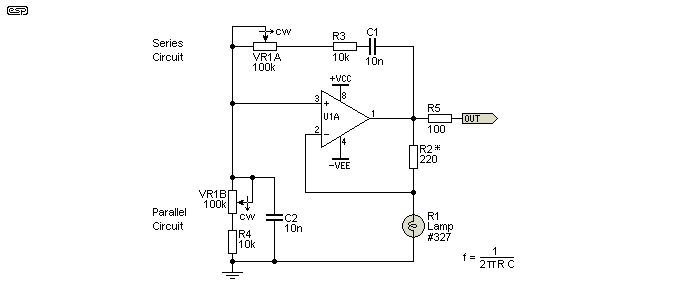
Figure 3.1 - The 'Classic' Wien Bridge Oscillator
R2 (marked *) needs to be changed to suit the lamp's resistance, with the value shown being about right for a 28V, 40mA lamp (however, see note below). The lamp must be a low current type, and even so will cause some pain for most opamps. Increasing the value of R2 may not allow enough current through the lamp to allow it to stabilise the output level, unless higher supply voltages are used to allow sufficient lamp current. Opamps are not designed to provide more than a few milliamps during normal operation, but the lamp may require 20mA or more (peak) before its resistance rises enough to be useful. See below for a detailed explanation of how the stabilisation process actually works.

| You need to be aware that lamps are not as straightforward as they may seem at first look. While running some additional tests on these circuits, I found that there are very large differences between lamps, even from the same batch. One may work properly, but another will cause the output level to 'bounce' uncontrollably. It should be possible to get stable operation by varying the value of R2, and the lamp needs an RMS voltage across it of at least 1/10th of its rated voltage. |
The Wien bridge itself is a phase shift network and a very basic (low Q) filter. At the critical frequency, there is a 0° phase shift, so there is positive feedback to the non-inverting input of the amplifier (in this case, an opamp). Figure 3 shows the general scheme of the Wien bridge, including the amplitude and phase response. You can see the basic filter response too. The upper capacitor causes the low frequency rolloff, and the lower cap causes the high frequency rolloff. The resistors (one in series, one in parallel) set the frequency - in this case 1.59kHz. This is calculated from the values of R and C (which must be identical for R1, R2 and C1, C2). Frequency is determined from ...
f = 1 / ( 2π × R × C )
f = 1 / ( 2π × 10k × 10nF ) = 1.59kHz
Many early Wien bridge oscillators used a variable capacitor rather than a pot. While this idea has great merit (variable capacitors will last several human lifetimes), it also means that all tuning circuit impedances are extremely high. Variable caps are very limited, and may have a maximum of perhaps 500pF. If you need to get to 20Hz, this means that the resistors need to be 15.9M for the lowest frequency range. Even a small amount of stray capacitance causes errors, and very complex shielding is needed to prevent hum and noise being picked up by the high impedance circuitry.
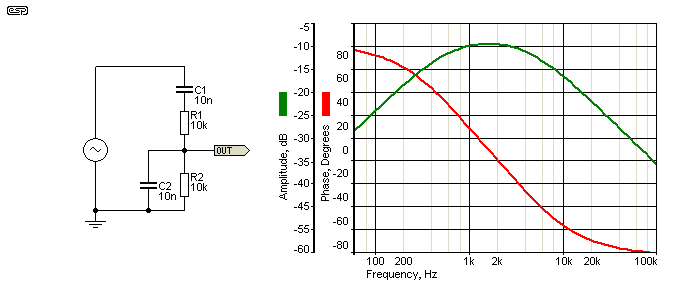
Figure 3.2 - The Wien Bridge And Response Curves
Figure 3 shows the Wien bridge itself, along with the frequency and phase response curves. As you can see, the amplitude is about 10dB down at the peak (exactly one third of the input voltage), so the amplifier must have a gain of 3 to ensure oscillation. In reality, the gain must be greater, or the oscillator will refuse to start or will stop. Unfortunately, the gain requirement changes very slightly due to small resistor (or pot) differences, but if it's only a tiny bit higher than needed, the amplitude will keep increasing until the output stage clips. Distortion is unacceptable at this point. This is why some form of amplitude stabilisation is essential.
With 1V input, the output of the Wien bridge is ideally 333.33mV - exactly one third. Even a very small variation between resistors and capacitors will change this though - a variation of ±1 ohm for the 10k resistors (0.01%) will change the gain requirements of the amplifier. The change is small, but it's enough to cause the oscillator to either stop, or increase level until it distorts the output. It may come as a surprise that a small incandescent lamp could possibly be accurate enough to allow the circuit to function in a useful manner.
The lamp is positioned in the negative feedback path around the opamp, and when cold will have a low resistance (all metal filament lamps have a positive temperature coefficient of resistance). This means that the amplifier will have very little negative feedback, so will oscillate immediately. As the output level of the opamp increases, more voltage appears across the lamp, its current increases, and so does its resistance. As the resistance of the lamp goes up, the opamp gain is reduced at the same time. A lamp is a PTC thermistor.
Within a relatively short period, the whole system (theoretically) reaches a state of equilibrium. Any attempt by the circuit to increase the output will result in greater lamp current, more negative feedback, so the level is prevented from increasing. In reality, it will increase, but hopefully only by a small amount. Likewise, should the level fall for any reason, current through the lamp filament falls, it cools a little, resistance falls, so gain is increased. Nearly all lamp or thermistor stabilised Wien bridge oscillators will show a variation of output level as the frequency is changed, so the stabilisation is definitely not perfect. Finding a lamp that provides a stable output is far easier said than done!
An alternative to the traditional Wien bridge shown above splits the amplification into two parts. The parallel section is used in an integrator circuit rather than as a passive network. Feedback is applied via the series network as shown below. This modification to the conventional Wien bridge network is claimed (by J.L. Linsley-Hood and others) to improve performance and reduce distortion caused by 'common mode defects' in the active device(s). This is real, and eliminating the common-mode signal does reduce distortion. Both opamps operate with zero common mode voltage, as one input is grounded and the other is a 'virtual ground'.
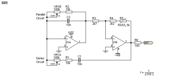
Figure 3B - Wien Bridge Oscillator With Two Amplifiers
A traditional Wien bridge as shown in Figure 4 has a significant common mode voltage (i.e. the signal voltage applied to both of the opamp's inputs), but in reality this is not usually a problem with modern devices, although the 'common mode' distortion may still be a limiting factor. The stabilisation network (lamp, thermistor, etc.) will invariably cause far more distortion than any modern opamp.
Distortion is reduced if the output is taken from the output of the integrator (U1A) because it acts as a low pass filter, so removes some of the harmonics. Because of the way the feedback network and integrator stage operate, the second stage operates with a gain of two for stable oscillation. Diode stabilisation is possible, but requires several circuit changes and will give unacceptably high distortion. Lamp stabilisation should also be possible, with the lamp placed between U1A and U1B in place of R3, and the feedback resistor around U1B altered to suit.
The heart of any sinewave oscillator is the amplitude stabilising system. Without it, the level will continue to increase until the waveform is clipped and severely distorted, or oscillation will die out over a period of time - assuming it starts at all. The range where the amplitude is stable and has low distortion is limited, and it is simply not possible to make an amplifier with the exact gain needed and expect it to work properly. In all cases with analogue sinewave generators, some means of stabilising the amplitude is needed. This can use diodes, zener diodes, or more sophisticated AGC (automatic gain control) systems. However, the most common (and most effective) amplitude stabilisation systems have used non-linear resistances as described below.
The demise of the specialised NTC thermistor that used to be the mainstay of audio oscillators is a serious blow, because the only available alternative is a small, low current lamp. These have a positive tempco, so the feedback network needs to be rearranged. Because their current demands are comparatively high (typically up to 20mA or more), this stresses most opamps. Lamps also have a fairly fast time constant, so distortion at low frequencies can be higher than is desirable because the resistance changes during the sinewave cycle.
RA series thermistors used to be made by a number of vendors, such as ITT, GE and various others, but absolutely no-one manufactures these components any more. The Chinese make a range of audio oscillators, and one I have seen uses a small lamp use for amplitude stabilisation. There are several techniques that can be used, and each has its place. One of the problems is that there is little or no reference material that I could find that discusses the options, and the strengths and weaknesses of each.
In short, these are the primary options ...
There is one other option too, and that's to deliberately clip the signal, and rely on a tuned filter to remove the distortion produced. Diodes or zener diodes are common for clipping limiters, but the amplitude will change with temperature. If clipping is used, it needs to be symmetrical to minimise even order harmonics. That means that diodes (or zeners) need to be matched and maintained in close thermal contact for best performance.
Filter complexity can be quite high for a low distortion output, and the circuit may end up needing to use multi-gang (3 or more) potentiometers for tuning. Apart from being extremely hard to get, these often have poor tracking. One or more fixed frequency filters can be used after a low distortion oscillator to reduce distortion, but this is generally limited to a few spot frequencies.
Even a tiny change of gain of an amplifier used in an oscillator circuit will cause the signal amplitude to increase until it distorts, or decrease until it dies away to nothing. The only way we can prevent either of these from happening is to provide an amplifier with more gain than is needed, and use automatic gain control (or controlled clipping) to maintain the effective gain at exactly the right amount to keep the sinewave amplitude stable. This isn't as easy as it might sound.
A problem that's becoming more of an issue than ever before is the rapidly shrinking availability of suitable JFETs. Where there used to be FETs for every occasion, most suppliers have reduced their stock to a few types that still remain popular. The very high performance, low distortion types have all but disappeared, unless you get them from China. This means they will have the type number that you ordered printed on the case, but inside could be anything that vaguely resembles a JFET (or even something else entirely).
For anyone looking for exceptionally low distortion, have a look at Project 174, which uses a novel sample and hold circuit to stabilise the amplitude. Unfortunately, the circuitry for the stabilising network is far more complex than the oscillator itself, which should give you an idea of just how important this part of the circuit really is.
A thermistor stabilised oscillator is shown above. Note that the thermistor and R2 have swapped places, because the thermistor has a negative temperature coefficient of resistance (NTC). As the level increases, more current flows through the thermistor, its resistance falls and this applies more feedback. Additional negative feedback reduces the gain and therefore brings the output level back to the desired voltage.
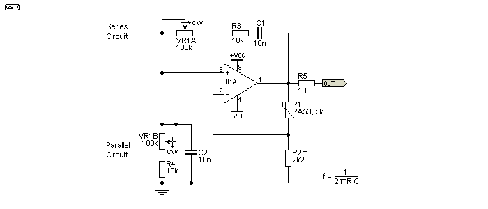
Figure 4.1 - Wien Bridge Oscillator Using Thermistor
Most people who have used audio oscillators will have found that the level bounces after the frequency is changed. A level change is caused by imperfect tracking of the frequency pot, and the bounce is caused by the lamp (or thermistor or other stabilisation technique) time constant. It always takes a while until the level settles to the normal value, because it is extremely difficult to obtain critical damping. In extreme cases, the bouncing amplitude can continue for some time - especially at very low frequencies. There is an inevitable trade-off that must be faced with all amplitude stabilisation circuits ... use a fast acting system that settles quickly but has high distortion at low frequencies, or a slow acting system that bounces for some time, but gives good performance at low frequencies.
In some (up-market) oscillators, different time constants are used depending on the frequency. This is hard to achieve if the time constant is dictated by a thermistor though - it is what it is, and it can't be changed. Electronic stabiliser circuits become even more problematical because of the increasing complexity of the overall solution. If the time constant is wrong, the oscillator may just operate in short bursts followed by silence. While this type of waveform can be useful, a poorly chosen time constant for the feedback stabilisation is not the way to achieve the desired result.
The photo below shows an R35 made by ITT. There is no real consensus on whether these are R53 or RA53, but the writing on the glass says R53, so I suppose that is fair indication that this device is an R53. I've also used the RA54, and as far as I can recall, there's no apparent difference. Most people have never even seen one, so I have remedied this by including the photo. I actually had to enhance the bead itself a little, because it's so small that it didn't show in the photo. The glass envelope is evacuated (i.e. a vacuum), and there is a getter at the end (note the silvered tip). The bead itself is tiny - apparently it's about 0.2mm in diameter, and it's suspended on very fine (platinum?) wires. The idea is that it is self-heating, and is relatively immune from ambient air temperature.

Figure 4.1.1 - Photo Of R53 Thermistor
Provided the tiny bead runs hot enough (perhaps 60°C or so), variations in ambient temperature will have little effect on the resistance of the bead. The whole idea is that its temperature is determined by the voltage across it. With a thermal time constant of about 1 second or so, the resistance doesn't change much with the applied AC waveform itself, only the RMS current through the bead is important.
Despite this, the R53 and similar thermistors (and lamps) will show increased distortion at low frequencies. Fortunately, this is rarely a problem, and few people bother to measure amplifier distortion below 100Hz or so. A low frequency, low distortion source can be useful to measure the distortion from electrolytic caps as their reactance becomes significant compared to circuit impedance, but the audibility of distortion is very low at low frequencies anyway, provided it's no more than a couple of percent (and low-order).
While there are many small bead type thermistors, this particular style in the vacuum tube is no longer made by anyone. People are constantly asking for assistance to find one (as a search will reveal), but no major supplier sells them any more. I accept that the market must be pretty small so they would be fairly expensive, but I am baffled as to why absolutely no-one seems to make a thermistor designed to stabilise audio oscillators. There is still a significant market for basic test equipment, and the audio oscillator is one of the most important. An entire enterprise (Hewlett Packard) started with a couple of blokes building audio oscillators in a garage - perhaps it's time to try that again. Chinese made audio oscillators are readily available from many sources, but I don't know what they use for stabilisation (although I know that some use small lamps).
Even lamps are starting to disappear, because panel indicators and (analogue) meter scale illumination are done with LEDs now. As long as the market still exists for small lamps there shouldn't be any real difficulty, but no-one knows how long there will be a demand. Once usage falls significantly, the cost of making them increases dramatically, limiting options even further.
For the time being, we'll assume a lamp for stabilisation, especially since no-one can get RA53 thermistors any more. The lamp's resistance at 25°C needs to be known, and a reasonable approximation of the current needed can be determined. The current will be enough to raise the lamp filament resistance so that it is well above ambient temperature, but not hot enough to glow visibly. Based on a number of fairly typical circuits available in application notes and elsewhere, a lamp filament current of around 7-12mA seems fairly common, which makes the lamp's warm resistance somewhere between 90 and 300 ohms. Look at Figure 2, and note that the feedback resistor is 470 ohms. For a gain of 3 as required, the lamp's filament resistance must be 235 ohms, and the opamp must be able to provide sufficient voltage swing and current to supply the feedback circuit's total resistance (705 ohms). If you can't see where I got the numbers from, I suggest that you read the beginners' guides for opamps and opamp circuits. Most of this is nothing more than Ohm's law.
 I tested a likely looking miniature lamp (almost identical to the one pictured). For some reason, the US based IC manufacturers who publish the application notes all seem to think that everyone not only knows what a #327 lamp is, but can get one easily. Application notes refer to this mysterious 327 lamp as if it were some kind of (minor) holy grail.
Yes, it seems to be readily available in the US, but elsewhere? It transpires that the #327 is a 28V lamp, rated at 40mA or thereabouts (1.12W on that basis). At full temperature, the filament will have a resistance of 700 ohms. A photo of a #327 lamp is shown to the left, so for those of us not in the US, at least we know what it looks like. (Ok, I do admit that these lamps can be obtained outside the US, but they are not readily available.) The application notes generally fail to state that many different types of lamps can be used, and they provide no details to make it easier for the constructor to choose something suitable.
RS Components has (had) a 28V, 40mA lamp (catalogue number 655-9621) that I believe works well. There are actually quite a few lamps that can be used, so it should be easy to find one that works. At least until these small lamps become unavailable! Unfortunately, no-one knows when that will happen, and maybe (if we're lucky) they will be with us for a few more years. Avoid lamps that demand high current (less than 40mA is preferred), and aim for a high operating voltage to minimise current. As noted below, the lamp voltage should ideally be at least of 10% of the rated voltage, although that's often hard to achieve.
Miniature 12-24V lamps with a rating of 1-2W (or less) should be alright for most applications. Cold resistance should be as high as possible - aim for at least 25 ohms if you can. Some testing will be necessary, because it's irksome to try to calculate the lamp's resistance at all possible operating conditions. Lamps with a rated voltage below 12V probably will not work, because they require more current than most opamps can supply. A buffer amplifier can be added (or a discrete circuit can be built) that can provide the current needed by the lamp if you don't have a choice.
The miniature bulb I used for the graph shown below has a cold resistance of 65 ohms (estimated), but even the ohm-meter supplied enough current to raise the resistance to 69 ohms. With a 220 ohm feedback resistor (as shown in Figure 3.1, the opamp output voltage will be 1.5V. You should see 500mV across the lamp, and total feedback current is 4.5mA - this means that the lamp's resistance must be 110Ω. Allowing for resistor tolerance (I didn't bother measuring the exact resistance) this all looks about right. It is also possible to use the resistance change to calculate temperature, but tungsten makes this task somewhat more difficult than more sensible metals, because the tempco changes (slightly) above ~100°C. However, as an approximation, tungsten increases its resistance by 0.0045% per °C. If we know that the resistance went from 69 ohms to 110 ohms, then this would indicate that the temperature of the tungsten has risen by 225°C, from 25°C to 250°C. This is so far above ambient temperature that normal variations cannot cause significant level changes.
R = R0 ( 1 + α ΔT ) Where R is final resistance, R0 is res. at ambient, α is the tempco of resistance (0.0045) and ΔT is the temp change in °C, or ... T = T0 + ΔR / ( α × R0 ) Where T0 is ambient, T is final temp (°C), ΔR is resistance change and R0 is initial resistance at ambient.
Measured distortion with the lamp I had was 0.02% at 700Hz and with an output voltage of 1.69V RMS. Not a wonderful result, but more than acceptable for most general purpose applications. Somewhat surprisingly, the measured distortion with the lamp was slightly lower than with an RA53 thermistor. The latter showed just under 0.05%, and both were measured at 700Hz. The distortion residual (just the harmonics after the fundamental has been removed by the distortion meter) was smooth in both cases, with predominantly 3rd harmonics. The circuits were tested on my opamp test board, and there was no shielding of any kind. I used 4558 opamps, which are roughly equivalent to the TL072, but have BJT inputs rather than FETs.
With the 220Ω feedback resistor, the lamp voltage was 550mV, meaning a current of about 5mA. There was considerable amplitude bounce, and the only 'cure' was to increase the feedback resistance and therefore the lamp voltage (and current). I increased the feedback resistor to 375Ω, which gave a lamp voltage of 1.39V (7.4mA) and an output of 4.16V RMS. This reduced the amplitude bounce, but it was still (IMO) unacceptable. A higher voltage would be preferable. However, that would make direct operation with an opamp impractical. Measured distortion was 0.03%.
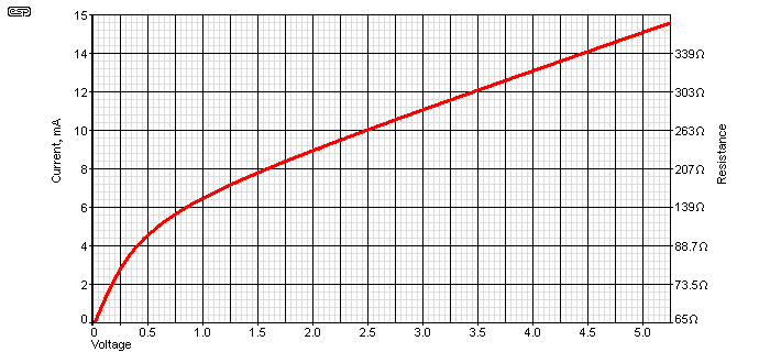
Figure 4.2.1 - Lamp Current Vs. Voltage
The image shown above is the voltage vs. current graph for a 28V, 50mA lamp (560Ω nominal), being one that I measured recently. It's cold resistance is less than 70Ω - it's difficult to measure accurately because even the multimeter's ohms range current (~800µA) causes the resistance to rise. For an 'ideal' part, the resistance would change very rapidly as current is increased, but the slope seen in the graph is fairly gentle. If used with a current of 8mA, the resistance is only 207Ω with a voltage of 1.66V, so to get a higher resistance means more current and a higher current drive circuit. Adopting the '10% rule' (explained below) we'd like to have a voltage across the lamp that's around 10% of 28V, or 2.8V. However, this isn't always feasible, and with the lamp shown the Figure 3.1 oscillator works 'well enough'. This isn't too difficult to achieve, and will result in an oscillator output voltage of about 4.5V RMS. This isn't a bad result, as the lamp current is low enough to ensure a long life, the output voltage is acceptable, and the filament temperature is well above ambient.
During testing, I determined that with a current of 10mA the filament appears dark, with an easily visible dull red glow appearing above 13mA. At 7.6mA, the formula shown above indicates a temperature of 437°C. The glow at that temperature is just visible in a very dark room with at least 5 minutes in complete darkness to allow your eyes to adjust. Unlikely though it may seem, using this technique you can see the glow from a soldering iron at ~350°C.
As noted earlier, you may have difficulty finding a lamp that works without continuous amplitude bounce. Like the unobtainable R53, suitable lamps may meet the basic specifications (28V, 40mA), but that does not mean they will work reliably. Several lamps I tried (ostensibly identical to the #327) did not work at all well in a low voltage circuit (±12V), and even when the feed resistance (R2 in Figure 3.1) was carefully adjusted, operation was less than perfect, with prolonged amplitude bounce before the level settled. These latest tests were done in October 2021, while original test results were from 2010, so it seems that the 'new' lamps are different from those of a few years ago. This doesn't bode well for the future. 
Note that some lamps may cause the output to be unstable, with continuous amplitude bounce (increasing and decreasing level, but never settling on a steady value). In extreme cases, you may even get a condition called 'squegging' - see Section 7 for an explanation of this phenomenon. This shouldn't happen with a simple lamp stabiliser, but I have seen it with some lamps I've tested. Upon further investigation, I've found that the lamp voltage should ideally be a minimum of 10% of the rated voltage. For a 28V lamp, that means no less than 2.8V RMS across the lamp, and preferably a little more. If you can meet this criterion, then lamp stabilisation works well, and distortion may be reduced further by adopting the arrangement described in Project 179. If the lamp were operated at 11mA (3V), the output voltage will be 9V RMS, requiring a supply voltage of at least ±22V.
The resistance vs. voltage (or current) curve of lamps is such that you'll often find that the amplitude of the sinewave changes slightly when the frequency is adjusted. This is due to imperfect tracking of the frequency pot, and that changes the gain needed to ensure oscillation. Ultimately, it's a careful balancing act - everything has to be 'just so' to get good results (and distortion performance is often still not a good as you'd like).
Be warned that many of the lamps that were common (and cheap) only a few years ago are now gone, and while there are a few reasonably priced ones left, they are rapidly diminishing. It's only a matter of time before they become very hard to obtain and expensive. I originally suspected that eventually most small incandescent lamps would have vanished from supplier shelves, but the supply (based on a recent search) indicates that there are more now than when this article was written. However, we can see small lamps selling for up to $5.00 or more (each!), and this can only get worse.
An optocoupler using LED and LDR makes a useful feedback network, and (unlike a lamp) it's very stable. The drawing below shows a circuit that I tested, and it works surprisingly well. Distortion is tolerable, at under 0.1% for frequencies above a few hundred Hertz, and despite the lack of filtering of the DC feedback signal (applied to the LED), performance at low frequencies is only a little worse. One might imagine that adding a capacitor in parallel with the LED would help, but most sensible values cause the amplitude to bounce continuously. A more complex filter circuit would help, but that defeats the purpose of a very simple design. This is likely the simplest possible sinewave oscillator, with no amplitude bounce and acceptable distortion for most purposes.
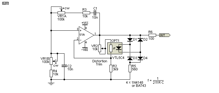
Figure 4.3.1 - Wien Bridge Oscillator Using LED/LDR Optocoupler
The diode bridge is powered directly from the opamp's output (with R5 to limit the peak current), and while you'd expect this to create distortion, it's well below the distortion caused by the LDR (it wasn't visible on the distortion residual displayed on my scope). The distortion residual is primarily third harmonic, and is surprisingly smooth with no sharp discontinuities that indicate higher order distortion. This scheme is very usable, and if you need a fairly decent sinewave, this is by far the simplest way to get it. The output level depends on the LED's forward voltage and that of the diodes, but my test unit provided 8V peak-peak (2.85V RMS).
Expect distortion to be around 0.4% if the distortion trim is omitted, but with it adjusted properly you can get below 0.1% quite easily, even at 100Hz. This is an unexpectedly good result, and while greater complexity can make it much better, as a general purpose oscillator it's pretty good as-is. If the distortion trimpot is omitted, this increases distortion, but lets the oscillator stabilise almost instantly, even with a grossly mismatched frequency pot. I tried it with one of the capacitors increased to 110nF (a 100nF cap in parallel with the 10nF caps shown), and it was easily able to oscillate reliably and stabilise almost instantly - that's a serious mismatch!
To set the distortion trimpot, it's adjusted so that the least possible appears across the LDR, while ensuring that there's enough gain to ensure reliable oscillation. That means the pot's set value will be in the order of 6k, but remember that the output level is also determined by the forward voltages of the diodes and the LED in the optocoupler. The amount of 'reserve' gain is that amount of gain, above three, which is the minimum required for oscillation if tuning values are 'fairly close' to the exact values. A 10k pot should be fine with most LDRs. A fixed resistor can be used once a workable value is found. It has to be a value that allows fast settling and reliable oscillation over the full frequency range.
The idea is to have the lowest possible voltage across the LDR, consistent with reliable oscillation. The distortion of any LDR is highly dependent upon the voltage across it, so by minimising the voltage you also minimise the distortion. If you aim for a voltage of no more than 200mV RMS across the LDR, distortion should be well below 0.1% (I measured 0.07% with VR2 set to 6k, and 160mV across the LDR). Oscillation was close to instant, with zero amplitude bounce.
Be aware that the signal amplitude will vary by at least -4mV/°C due to the tempco of the diodes (Schottky types should be a little less). The LED will also show some variation, but I didn't quantify that. I heated the rectifier/ LED/ LDR network with a hot air gun, and reduced the level from 1.77V RMS to about 1.6V RMS (it was pretty hot!). That's a change of less than 1dB, and is probably alright for most purposes. In reality it's unlikely to be an issue, because the temperature of most workshops will be set to something that's comfortable for people, so shouldn't vary by more than ~10°C.
For a simple, easily set up general purpose oscillator, this is very hard to beat, and it works fine even with very ordinary opamps. Expensive, low distortion opamps aren't required, because the distortion is limited by the LDR. If you can't get the VTL5C4 shown, You can make your own DIY optocoupler by following the detailed instructions shown in Project 145.
Since the ideal thermistor is unobtainable, lamps may require more current than we have available and LDRs have more distortion than we may desire, we need to look at alternative methods. Even the supply of lamps is shrinking, with far fewer available now than even a 2-3 years ago. I have already shown a FET used as a variable resistance, and these are convenient, cheap, and work well enough so long as the (AC) voltage across the FET is kept to a minimum. Providing an AC signal at the gate which is exactly half the voltage on the drain helps dramatically, and even harmonics (2nd, 4th, 6th, etc.) are effectively cancelled, leaving only the small odd harmonic residuals. C2 would normally be connected in series with R5, but that creates a second time constant.
To prevent this JFET 'feedback' from creating two time constants, one based around each capacitor - C1 and C2 (the latter shown in grey), it's better to direct-couple the JFET gate to C1, and use C2 in the drain circuit as shown (in series with the feedback circuit). C2 needs to be a relatively high value, such that there is little or no voltage across the cap at any frequency selected. This means it will be an electrolytic because a value of at least 220µF is needed, based on 'typical' feedback resistance values and a minimum frequency of 10Hz. Lower frequencies require a larger capacitor. Doing it the way shown does add a small perturbation as the JFET's gate voltage changes, but as there's only a few microamps available through R4 and R5 it has a minimal effect on the output (far less than amplitude bounce, which will last for around 500ms as simulated).
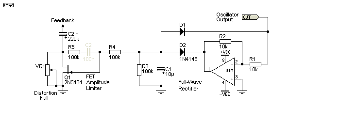
Figure 4.4.1 - JFET Electronic Stabilisation
The JFET circuit has only one time constant when connected as shown, and that makes it fairly easy to avoid unacceptable bounce when the frequency is changed. You would normally expect to see C2 in series with R5, but that creates another time constant. As shown, all requirements for a stable loop and minimal distortion are satisfied. While there are countless JFET stabilised oscillator circuit to be found on the Net, almost none are wired properly. Many don't include the drain to gate feedback at all (so distortion will be unacceptably high), and a few get tantalising close, but get the feedback path wrong.
Done properly, a JFET can provide distortion performance that is as good or better than a lamp or thermistor. In simulations (real life will be worse), I've managed to achieve less than 0.001% THD, using both Wien bridge and state-variable topologies, but it's not known how well that will translate to reality. Remember that the lower the voltage across the JFET, the lower the distortion can be, but there's always a limit imposed by imperfectly tracking tuning pots, as this requires a greater available variable gain range.
While discussed above in Section 4.3, a bit more information is warranted. The LED/ LDR circuit has only one time constant - LDRs have a slow response to illumination and a slower response when light is reduced or removed. However, it's usually necessary to include some filtering after the rectifier to minimise distortion at low frequencies. This extra time constant can cause serious bounce, and in extreme cases, what's known as squegging. This refers to the behaviour of an (analogue) electronic circuit that appears to function normally for a period (typically a few milliseconds), then shuts down for a period (from milliseconds to seconds) before repeating the process continuously. The design of control-loop time constants is almost a complete science in itself, and it is very easy to make a seemingly insignificant change that either causes or cures the problems. Squegging can be very difficult to prevent when there's more than one time-constant in a control-loop.
Needless to say, control-loop theory is outside the scope of this article, but during both physical testing and simulation of the circuits shown, I encountered squegging on several occasions. Multiple time constants that are reasonably close together will cause problems, so it is generally necessary to ensure that time constants are widely different if more than one is involved. If low frequency performance is of little consequence, C1 in the drawing below can be eliminated (although it must be admitted that it doesn't help very much anyway).
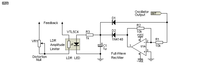
Figure 4.4.2 - LED/ LDR Stabilisation
To prevent amplitude instability, the filter cap for the LED/LDR opto coupler feedback circuit is much smaller than it really should be. LEDs are extremely fast, but LDRs are relatively slow, with the VTL5C4 taking several seconds to return to maximum resistance after illumination. The experiments I performed showed that adding a filter cap of a useful value after the diodes caused squegging, and while I'm sure that there is a combination that would work, I simply left it out to prevent problems (thus, you too can feel free to omit C1 in the second circuit). However, this limits the low frequency range because distortion becomes very high at frequencies below ~50Hz or so (this depends on the specific opto coupler, as there are many different types with different response times).
There is one major difference between the way these two circuits work. The FET has minimum impedance with no signal, and increasing the signal level increases the FET's impedance. In this respect, it is the equivalent of using a lamp, so must be in the same electrical location that would otherwise use a lamp. For the Wien bridge, this means that the FET connects from the feedback node to ground.
The LED/LDR opto coupler is the equivalent of a thermistor as it has maximum resistance with no signal, and the resistance falls as the level increases. While the operation can be electrically reversed, doing so simply adds more parts for no real benefit. In both cases, it is important to minimise the voltage across the FET or LDR. Smaller voltages and/or currents mean lower distortion, so the variable resistance element should use series or parallel resistance (or a combination of both) to achieve the highest linearity.
Naturally, you must ensure that there is always enough available gain to ensure that oscillation starts reliably, and this influences the distortion null setting. While you may be able to get low distortion from the Distortion Null control, you may then find that the circuit refuses to oscillate at high frequencies or when the oscillator is first turned on. This means that some distortion performance must be sacrificed to ensure reliable oscillation under all conditions. An LED/LDR optocoupler can be used to stabilise any oscillator, with placement depending on the topology.
Another option is a LED/FET optocoupler, such as the Fairchild H11F1. I've not tried them, so can't comment based on direct experience. However, since the active element is a FET, we already know that the level has to be kept low to minimise distortion. The datasheet claims that low level AC and DC can be controlled "distortion free" (a quote from the datasheet), but I find this a little difficult to accept. Many posts on forum sites complain of high distortion with this (and similar) devices, so they are probably unsuitable for a low distortion oscillator gain control. There is no facility to provide the ½ AC voltage at the gate to cancel odd harmonic distortion, so it's unlikely that performance will be acceptable.
A high quality VCA (voltage controlled amplifier) such as the THAT2180 (or SSM2018 which is now obsolete) could be used for amplitude stabilisation. See Project 141 to get an idea of how these work. Distortion is very low, at a claimed 0.02% for the THAT2180B. Using one in an oscillator would be a challenge though, and in practice it will be necessary to ensure that the VCA only provides a small fraction of the feedback signal to minimise its influence on the final THD figure. Getting a stable output may prove to be a challenge.
There are actually relatively few sinewave oscillator topologies around. Given the long-term popularity of sinewaves, one would expect a plethora of different designs, but this is not the case. Certainly, there are more options for fixed frequency oscillators (such as phase-shift oscillators for example), but variable frequency is expected by most users so the options become much more limited. Those shown here are representative only, and include JFET, diode and lamp stabilisation.
Stabilisation is the bane of all sinewave oscillators, because it either works quickly but with high distortion, or works slowly so has low distortion, but causes amplitude bounce when frequency is changed. Junction FETs are convenient but have relatively high distortion unless the level is kept very low (preferably under 100mV, ideally mush less). LED/LDR opto-couplers would seem to be a perfect choice, and if used appropriately can give low distortion. Thermistors and lamps have better linearity than FETs or LDRs, so one would think they'd will win every time, but this isn't always the case.
Since all analogue sinewave oscillators require amplitude stabilisation, this is still a challenge. When a FET is used, it is a well known phenomenon that distortion is minimised if the gate has exactly half the AC signal level at the drain. Second harmonic distortion is virtually eliminated, leaving predominantly third harmonics. Interestingly, most of the application notes that use electronic stabilisation only show half-wave rectification. A full-wave rectifier is preferable, as it reduces the ripple voltage in the stabilisation loop which helps reduce distortion. If the FET's internal structure isn't perfectly symmetrical, it may be necessary to vary the AC gate voltage (at the sinewave frequency) slightly above or below the halfway point to get the lowest possible distortion.
The first of the alternatives is based on a state-variable filter, and although fairly complex, it performs well. The biggest advantage is that the sweep range can be made fairly wide - up to 100:1 is possible, although this can only be achieved realistically if a close tolerance dual pot is used for tuning. Distortion performance is acceptable, but is limited by the FET. Although I haven't tested this design with a thermistor in place of R6, I'd expect performance to be quite good. This design also has a cosine wave available from the output of U1B. A cosine wave is a sinewave, but displaced by 90°. The usefulness of this is dubious for a general purpose oscillator, although there are a few specialised applications where a cosine waveform is needed. Few audio hobbyists will ever require a cosine output. It doesn't matter which output is used if you only require a sinewave, but the second integrator (cosine output, U2A) gives a slightly lower distortion.
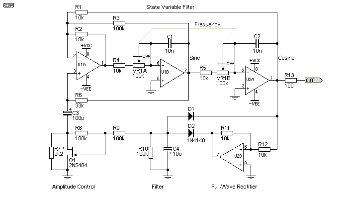
Figure 5.1.1 - Sine-Cosine Generator Using State Variable Filter
This is an interesting circuit, partly because I could find no definitive origin. Parts of it are shown in an Intersil application note, and there are several sites that either show either a very similar circuit as indicated in the references, or have a link to the page. Distortion performance depends almost entirely on the FET used. I've shown a 2N5484, and while these were common, it's possibly one of the worst FETs around for this application. The original showed a 2SK30A, but it is a discontinued device and therefore will be difficult to obtain. The resistor in parallel with the FET (R7) needs to be selected for reliable starting and lowest distortion (it's therefore a compromise). The available range of JFETs has diminished greatly in the last few years, and good candidates are now harder to find. The circuit has been revised so the JFET is used properly (without adding an additional time constant).
R8 and R9 combine to ensure that the gate has exactly half of the signal present at the drain, and this reduces distortion (simulated) from 0.2% to 0.009%. Without the drain to gate feedback, distortion is increased. I have found it wise to use simulator distortion figures as a guide only, so expect the figures above to be somewhat higher than the simulator claims. See section 7 to look at electronic stabilisation in a bit more detail.
Frequency is determined using the same formula as the Wien bridge. In the example shown it has the same frequency range as the Wien bridge above.
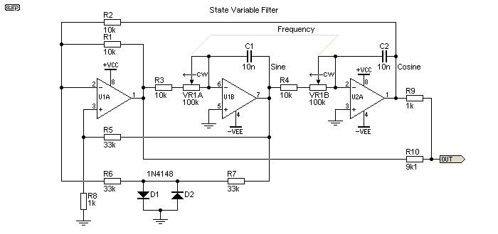
Figure 5.1.2 - State Variable Filter Oscillator With Diode Stabilisation
Another variant of the state variable filter oscillator is shown above. This uses diode stabilisation and distortion cancellation (R9 and R10). This is an especially interesting circuit, since it is easily capable of respectably low distortion (around 0.05% is possible), while still using simple and cheap diodes for amplitude control. R8 (1k) is selected for reliable oscillation, and can be increased to reduce distortion, but the oscillator may not start if the value is too high. The two diodes must be accurately matched for forward voltage at a current of around 0.5mA to ensure waveform symmetry and minimum distortion.
Distortion cancellation relies on the primary distortion component being third harmonic, and this will always be the case when matched diodes, thermistors or lamps are used for amplitude control. Distortion components cannot be accurately predicted if LED/LDR optocouplers or FETs are used. The circuit as shown has a fairly high output impedance, so must be followed by a buffer stage.
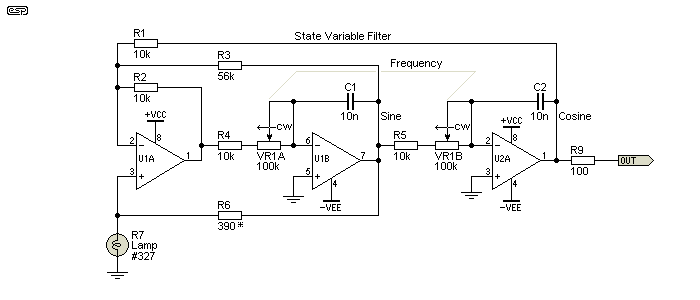
Figure 5.1.3 - State Variable Filter Oscillator With Lamp Stabilisation
Finally, you may also be able to use a lamp to stabilise the amplitude. The same issues as with a Wien bridge apply, and it may take some experimentation to find a lamp that works properly, without squegging (see Section 7 for an explanation of this phenomenon). R6 will need to be adjusted to suit the characteristics of the lamp used. As a rough guide, R6 needs to be low enough to ensure that the lamp operates with a minimum of 10% of its rated voltage. Alternatively, you can adjust R3, with a lower value providing more feedback so the circuit oscillates more readily. Note that the opamps need to be capable of significant current to power the lamp, so NE5532 or similar are suggested. If you wish, the output of U1B to R6 can be buffered by a non-inverting opamp buffer to minimise distortion. An additional opamp may cause distortion performance to be reduced, especially at higher frequencies where the small extra phase shift may become 'significant' compared to the waveform's periodic time (1/f).
There are several different configurations for the basic state-variable filter, so while you may see circuits that appear slightly different, the basic operation is the same.
The state variable filter based oscillator shown above is also known as a quadrature oscillator, because it produces two sinewaves in quadrature - they are exactly 90° apart (sine and cosine). One sinewave is available from U2A as shown (technically, this is the cosine, delayed by 90° with respect to the sine output), and another can be taken from U1B. The cosine is sometimes preferred because it has lower distortion because of the second integrator.
This is not a particularly user-friendly oscillator, because there are three time constants that must be changed for tuning. All three must be identical, and the oscillation frequency is given by the normal formula. This is a common circuit, and is used where sine and cosine waveforms are needed but where only a single fixed frequency is necessary.
The lowest distortion depends on how it's wired. Sometimes the sine output may have lower distortion with a different clipping network. There are many different ways you may see this circuit stabilised, but nearly all use diodes. This invariably limits the distortion performance. Amplitude depends on the diode voltage, and a more sophisticated arrangement is necessary if constant level is important.
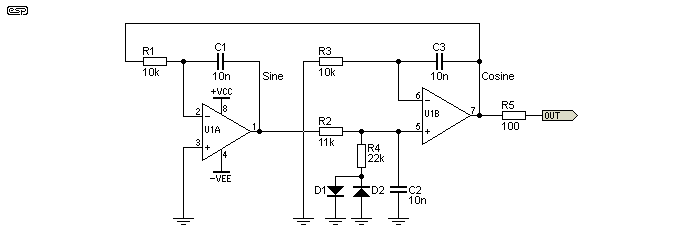
Figure 5.2 - Quadrature Oscillator Using Three Integrators
The lowest distortion is obtained from the sine output (U1A), but there are several different ways that the circuit can be stabilised, and lowest distortion depends on where the signal is clipped. Residual distortion can be hard to eliminate. In general, THD below 1% is reasonably easy to achieve, but expecting less than 0.2% is probably optimistic. It is possible to use alternative amplitude stabilisation techniques, but as it's not a 'friendly' oscillator this isn't covered. The diode stabilisation certainly works, but distortion performance is less than stellar.
The connections shown can vary, but the circuit must be arranged to have a loop gain of more than unity. Making R2 11k (rather than 10k) increases the gain, which is pulled back by the diodes and R4. This does affect the frequency slightly. Other variation may also be seen, but the net result is much the same no matter how it's arranged.
There are a number of variations on this theme, but this particular version is interesting in that it only requires one resistor value to be changed to change frequency. A single-gang pot eliminates any issues with tracking, and this problem is actually worse than expected. Few (affordable) dual-gang pots offer good tracking between sections, and this circuit solves the problem by not needing a dual-gang pot.
Apart from anything else, the filter section itself is mildly interesting. If you look at the various active bandpass filters, you will see that this is really a multiple feedback bandpass filter, No-one seems to bother mentioning this, yet it surfaces in several application notes and on a number of websites. National Semiconductor refer to it as an 'easily tuned' oscillator, which is certainly true enough. Stabilisation is achieved using clipping diodes, but a thermistor, FET or LED/LDR can also be used with appropriate circuit changes. Distortion can be very low if a linear stabilisation technique is used, but even with diodes can be under 1%.
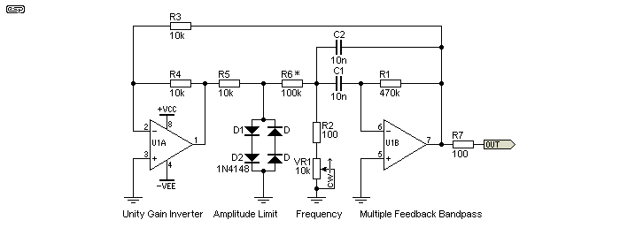
Figure 5.3 - Oscillating Bandpass Filter Oscillator
There are two major disadvantages of this circuit that are not mentioned in any of the application notes I've come across. High frequency performance is very limited, because the filter stage (around U1B) operates with considerable gain. As the frequency is increased, the tuning resistance (R2 + VR1) is reduced to the minimum, and this attenuates the signal from the diode clipper. With the values shown and at maximum frequency, the opamp needs a gain of at least 30, and preferably a lot more. Very fast opamps could be used, but they are expensive and in my opinion are wasted on this circuit. One common example on the Net shows VR1 as 1k and R2 as 51 ohms. The opamp is operated at high gain to get a high Q (which minimises distortion), and this limits the maximum usable frequency.
The other problem is that the tuning range is comparatively small. To maintain acceptably low distortion, the tuning ratio is only about 4:1 - rather inconvenient and much lower than that from other topologies. Distortion is inversely proportional to frequency, so at the minimum frequency the THD will be roughly 4 times that of the maximum frequency. These two issues confine the circuit to the 'interesting but not very useful' basket. This is contradictory to some of the claims you may see for this circuit, but I've built and tested one so I know its limitations. With the pot at minimum, the operating frequency is approximately equal to ...
f = 1 / ( 2π × C × √R1 × ( R2 + VR1 ) )
f = 1 / ( 2π × 10nF × √560 × 470k ) = 981Hz
The most (potentially) useful part of this design is the filter. While it's simply an adaptation of a MFB bandpass filter, using it as a variable tuned filter is unusual. I have used the same arrangement for tunable filters in a couple of projects, but only over a very limited frequency range. The Q varies with the pot setting (high resistance gives a low Q), but in many cases this is not a major limitation. Fig 5.3 has been redrawn to show the MFB filter in its 'normal' schematic representation.
To calculate the MFB filter, use my MFB Filter (an executable program written in Visual Basic 6). The popup when you click the link will ask if you wish to save the file. It's clear of any virus and it does not connect to the Net. It does require the VB6 runtime library, and this should be present on all recent Windoze machines. Windows will probably give dire warnings about running the file, which can be ignored.
This is a very uncommon circuit, and is one that I happened to find in a commercial product. Although it is single frequency, it's a potentially interesting circuit because it is capable of fairly low distortion, despite the use of zener diodes for amplitude control. It typically has a higher output than many of the other circuits, and as shown below produces about 5V RMS output level with a distortion of as little as 0.04% (with considerable tweaking!).
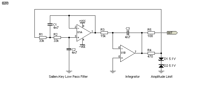
Figure 5.4 - Low-Pass Filter + Integrator
Although the circuit is not complex, amplitude stability with changes in both supply voltage and temperature are quite good, but tuning is difficult. With the values shown it oscillates at about 1kHz, but no resistor value can be changed that affects only the tuning and not amplitude. This makes it suitable for fixed frequencies only. The value of R3 is quite critical - it needs to be low enough to ensure reliable oscillation, but not so low that the output distorts. The circuit gain around the integrator is almost exactly 2 (6dB). The voltage losses in the filter and zener clipping circuit need to be exactly replaced by the integrator gain to maintain oscillation.
As mentioned - interesting, but only marginally useful. Determining the frequency is rather irksome, and can only be approximated. In theory, the frequency for the circuit as shown is 1026Hz - roughly based on the standard formula ...
f = 1 / ( 2π × C1 × R1 )
This is also influenced by the integrator (U1B) time constant determined by R3 and C3, and this makes it considerably less predictable. When simulated, the circuit oscillates at 1016Hz, but a test circuit oscillates at about 970Hz. This is outside the expected variation based on typical component tolerances. Although the circuit is (surprisingly) quite stable in operation, virtually every component changes the amplitude and frequency. The only exception is the zener diodes which may be changed with only minor effect, but even R4 changes both amplitude and frequency!
Of the alternatives, this is by far the best I've found. For most applications will easily beat almost anything else. It is described in Project 86, and has very good performance. The only down-side is that the dual-gang pot needs to track fairly accurately to prevent momentary drop-outs (bounce is virtually non-existent), but it's much better than a Wien bridge oscillator in that respect. In addition, PCBs are available from ESP - see the pricelist.

Figure 5.5.1 - Basic Phase Shift Oscillator
One method of using all-pass networks is shown above. There are two all-pass filters, with a variable resistance that allows a (theoretical) frequency range from 20Hz to 20kHz. With the values shown, the range is from 30Hz to 720Hz. The final amplifier has just over unity gain, with the diodes acting as amplitude limiters. The low-level gain is determined by the values of R8+R9 (in series), divided by R7. This gives a gain of 1.085 - just sufficient to ensure oscillation. When the peak amplitude attempts to exceed the diode voltage (650mV × 2) the diodes conduct and prevent the amplitude from increasing. The frequency range should be limited to no more than ~20:1, otherwise it's too hard to set high frequencies accurately.
While the ability to operate over the full audio frequency range looks like a good idea, mostly it isn't. It will be almost impossible to set a particular frequency in the two upper octaves because of the pot - the total resistance will be less than 10k for any frequency above 2.3kHz using 6.8nF caps, and setting that with a 1MΩ pot is irksome (to put it mildly). For that reason, the P86 circuit (and the simplified version shown below) divide the frequency range into three bands.
This principle is then taken a step further by incorporating distortion reduction. In the following circuit, the phase shift networks are inverting types (series capacitor and resistance to ground), but this makes no difference to operation.
Because of the 'feedforward' distortion cancellation signals, the output can achieve a distortion as low as 0.1% with diode clipping. A thermistor can be used instead of diodes to reduce the distortion even further, but the problem of obtaining thermistors remains (of course). There is no reason that an LED/LDR solution wouldn't work equally well, although this has not been tried. Unlike most of the alternatives, this oscillator can have a much wider frequency range than expected - up to 25:1. This means that the entire audio band is more than adequately covered by only 3 ranges ...
10 to 140 Hz
140 to 1,960 Hz
1,960 Hz to 27.44 kHz
To be able to get beyond 20kHz requires fast opamps, and is usually not needed for the majority of tests. A more realistic upper limit is around 15kHz, and a reduced frequency range (such as 14:1 as shown above) allows more accurate frequency adjustment. The minimum frequency is limited only by the amount of capacitance you can use for CT (timing capacitors) and RT (timing resistor + pot). There is no theoretical lower limit for frequency, and if the diode limiter is used (rather than a thermistor or electronic stabilisation scheme) distortion will remain low at well below 1Hz. Frequency calculation uses the same formula as the Wien bridge.
Please note that the term 'feedforward' is not strictly correct in the context used here, but it does convey the principle fairly well. Also, much like the state-variable filter based oscillator, I found little information on the Net about this circuit, except for the contributed project published on my site. It is based on a circuit described in the February 1982 issue of Wireless World (now Electronics World), contributed by Roger Rosens. The original relied on a long obsolete NTC thermistor for amplitude stabilisation.
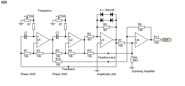
Figure 5.5.2 - Phase Shift + Distortion Cancellation Oscillator
The secret of how this design achieves such low distortion from a diode limiter and no filtering lies in the final opamp. In much the same way as the diode shaper shown below sums the various outputs to approximate a sinewave, the final stage sums signals with a defined phase displacement. The result is almost complete cancellation of third harmonic distortion, along with a worthwhile reduction of fifth and seventh harmonics as well.
Th frequency is set by the two phase-shift networks, and is determined by the values of RT and CT (timing resistors and capacitors). RT includes the fixed and variable resistors. The frequency is determined by ...
fo = 1 / ( 2π × RT × CT )
Overall, this is probably the most useful of all the different types shown, however it does use more opamps than most, and will use even more if electronic stabilisation is added. Because of the multiple summing points that give this circuit its low distortion, a lamp cannot be used, so amplitude limiting will be via the diodes as shown, or an RA53 thermistor if you can get one.
This general class of circuit is simple to build if you need a simple oscillator in a hurry. They don't require stabilisation (although it can be applied with some effort), and are very common circuits. Traditionally used in valve guitar amps as the tremolo/ vibrato oscillator, there are probably many millions of them around. The frequency formula is not especially accurate, and although frequency can be changed by around 5:1, the amplitude usually changes too. Any timing resistor can be changed to change the frequency, and for a limited range (~4:1), R3 can be varied with only small amplitude changes.
Although shown with feedback using R4 and R5, the opamp can be operated open-loop (maximum possible gain) by omitting R5 and shorting R4. Output level will be higher, oscillation is absolutely guaranteed (as long as it's within the opamp's range of course), but distortion is greater and frequency stability isn't as good.
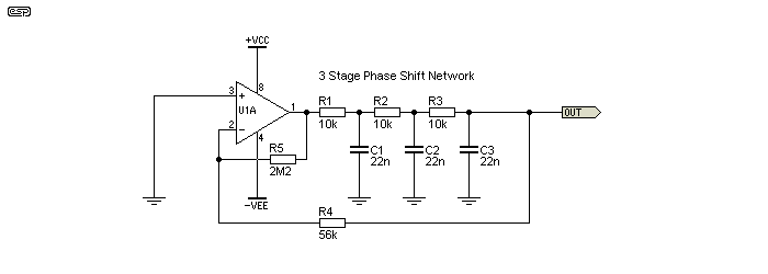
Figure 5.6.1 - Phase Shift Oscillator
With the values shown, the frequency is 1.73kHz, with 0.4% distortion (only odd harmonics). Output voltage is 370mV with ±15V supplies. Traditional frequency calculation isn't possible, because each RC network is loaded by the one following. That means that more gain is needed from the opamp, and the phase shift network interactions make straightforward calculations difficult. If the gain of the amplifier stage is reduced with feedback, there must be sufficient gain to ensure that oscillation is reliable. The amount of gain needed is normally around 30, but is increased if the three RC networks are not identical.
fo = √6 / (2π × R × C) = 1.77kHz (This is approximate, and only works when all values of R and C are equal)
If R3 is increased to 33k, the frequency decreases to about 1.2kHz. However, you'll need to increase the value of R5 to get more gain or the circuit won't oscillate. This is a useful circuit, but it has limited application. For wider frequency range adjustment, all three resistors can be changed and this will keep the amplitude the same. Triple-gang pots are as common as R53 thermistors, so this is not really a viable option. A dual-gang pot could be used in series with R2 and R3, which will increase the frequency range. Output level will vary with frequency though. Note too that the output is at a high impedance, and must be buffered to prevent the external load from affecting the frequency. The signal at the output pin of the opamp has the highest distortion, so isn't generally very useful.
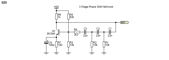
Figure 5.6.2 - Transistor Based Phase Shift Oscillator
You will see this circuit used with the resistors and capacitors interchanged as shown above. This method of wiring the phase shift networks is actually necessary for single transistor, FET or valve circuits, but it is not correct if the gain stage is an opamp. Note that the output is from the transistor's collector, and distortion is fairly high because the RC networks can't filter out the harmonics. The frequency isn't particularly stable, and a simulator indicates that the above circuit oscillates at 380Hz. This may not be expected, as one would think it should run at the same frequency as the opamp version because the RC networks use the same values. The change to the feedback path affects the way the circuit works, and in this circuit, every component affects the frequency.
While an opamp will certainly oscillate when connected the same way, this arrangement provides poor frequency stability and high distortion, so its output is a very low quality 'sinewave'. As an alternative circuit using opamps it's completely pointless and I suggest that you don't bother. It's just a carry-over from the single valve and transistor circuits as shown above, but it makes no sense to wire an opamp phase shift oscillator this way.
More advanced versions of the same principle also exist, and may even be given exotic (or stupid) names (such as 'Bubba' oscillator). It doesn't matter what you call it, it's still a phase shift oscillator. Although traditionally phase shift oscillators have used 3 sections, more can be added - the 'Bubba' oscillator uses 4 phase shift networks. Extra sections give the opportunity for lower distortion, but at the expense of overall parts count. Because of the buffers, the output can be loaded by an external impedance without affecting frequency. Buffer stages reduce voltage losses, but add complexity and cost.
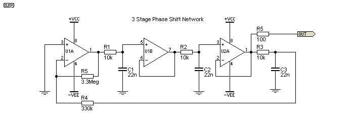
Figure 5.6.3 - Buffered Phase Shift Oscillator
Adding the buffers to a standard phase shift oscillator means that each RC network acts independently. Using 3 opamps as shown above means that the RC networks are truly independent of each other, although the final RC network (R3, C3) is loaded by the feedback resistance. Provided the resistances are high enough, loading is minimal. The gain opamp (U1A) should be used with feedback as shown, or the circuit will have excessive distortion. Each RC network contributes 60° of phase shift, providing 180° in total. Oscillation frequency is 1.26kHz in a simulation, and this circuit requires a gain of at least 8 for sustained oscillation. Frequency is approximately ...
fo = √3 / ( 2π × R × C ) = 1.25kHz for the values shown
I have no idea where the name came from, but the Bubba (ok, I'll drop the quotes  ) is actually a useful design for fixed frequencies. Apart from fairly low distortion, it appears to have good frequency stability, which may be critical for some applications. The lowest distortion is from the junction of R4 and C4, but that requires yet another buffer so the load doesn't change the frequency and amplitude. Taking the output from the point shown is a reasonable compromise, and will give a sinewave with under 0.5% distortion.
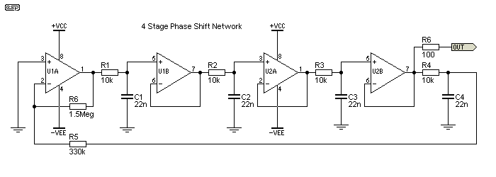
Figure 5.6.4 - Bubba Phase Shift Oscillator
Adding a fourth phase shift network means that each RC network only contributes 45° phase shift, and this is claimed to improve the frequency stability. This is not a circuit that I've built and tested, but extensive simulations confirm that it performs as expected. Oscillation frequency with the values shown is 720Hz, and the Bubba circuit requires a gain of at least 4 for sustained oscillation. Frequency is approximately ...
fo = 1 / ( 2π × R × C ) = 723Hz for the values shown
While it looks relatively complex, it's just repetition, and the cost is fairly low - especially if a quad opamp is used. For maximum frequency and amplitude stability, the opamps used should be FET input (for the high impedance) and rail-to-rail output so that output device saturation voltage has no effect. There are many suitable opamps, and CMOS types should be well suited to any of the phase shift oscillator designs.
A technique that was popular some time ago was the BFO. Two high frequency oscillators were used, generally operating at several hundred kHz or more. The two signals were fed into an RF mixer, and the audio output was the difference frequency. For example, if one RF oscillator operates at 1,000,000Hz and the other at 1,000,100Hz, the difference frequency is 100Hz.
You may well ask why, and today no-one would bother. BFOs were used to generate sweep signals, and can easily cover from 20Hz to 20kHz in a single sweep. The change required for an RF oscillator is comparatively small in percentage terms (20kHz is only 2% of 1MHz), and was easily accommodated with the valve circuitry that was available at the time. Sweep signals are common today, and are primarily digitally derived as part of a testing suite for amplifiers, speakers, etc. There is still a need for stand-alone sweep generators, but it's far easier (and a great deal cheaper) to use a digital waveform generator or a PC based system, several of which can be obtained on-line as a free download.
One of the issues is that distortion is comparatively high compared to most modern oscillators, and it will be difficult to keep distortion below around 2% even with a reasonable output filter. There will nearly always be vestiges of the two RF frequencies as well, because RF can be notoriously difficult to eliminate completely. BFOs are interesting, but are largely a thing of the past. They do have some nostalgia value though, and for that alone some readers may like the idea.
However, there is no plan to provide circuitry for a BFO, and as noted in the previous section, a single sweep from 20Hz to 20kHz can be achieved with an all-pass filter oscillator.
This is another single frequency oscillator, and is included because it's referenced widely on the Net and you may find it useful as a quick project or just for experimentation.
There are many circuits that use a squarewave oscillator as the basis for generating a sinewave, and what's needed is a filter to remove the harmonics (3rd, 5th, 7th, etc.). Despite claims you might see, this is not terribly effective, and the output is a fairly rubbish version of a 'sinewave'. While tuning is theoretically simple, the filter has to be tuned too, and that makes it quite difficult because you'll need a triple-ganged pot (you can get them, but they are not common and fairly expensive). This means that it's not really a viable way to generate a very poor attempt at a variable frequency sinewave.
According to the literature [ 10 ], it's supposedly a worthwhile circuit, but a quick examination reveals many weaknesses. Firstly, the frequency depends on the voltage appearing across R1 and R2, and that depends on the saturation voltage of the opamp. Most opamps can get to within ~1.5V from each supply rail, but that changes with loading and temperature. In theory, the circuit is self-correcting, because both positive and negative feedback come from the output of U1A. In reality, the frequency stability is ok - not great, just ok.
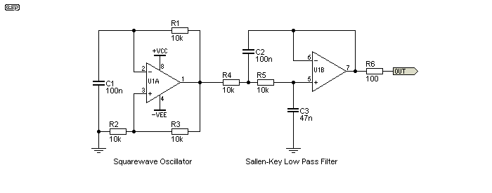
Figure 5.8 - Squarewave Oscillator + Filter
With the values shown, the frequency is 467Hz, and the output level is 980mV RMS. The application note referenced claims that the filter section should be tuned to the same frequency as the oscillator, but distortion is woeful if you do that. Even with the filter shown (tuned to 239Hz), the distortion is still almost 4% - hardly a good result. However, you may find a need for a low cost oscillator, and this general arrangement works well enough.
Note that the formula shown in the application note doesn't work, so to change frequency you can scale the resistor values (R1, R4 and R5) to change frequency. I don't propose to work out a formula for the frequency - you'll just have to experiment (a simulator is good for basic testing). While it can be improved from the circuit shown, for the most part I'd suggest that it's not worth the effort. Many of the alternatives shown above will give better results, simpler (and more accurate) tuning, more predictable performance and for around the same cost.
The twin-t (aka twin tee) oscillator is something of an oddball in several respects. Rather than using a tuned bandpass filter, it uses a tuned band stop (notch) filter, and the opamp is operated with positive feedback via R1 and R2, with the notch filter in the negative feedback path. Less positive feedback (by making R2 a lower value) results in lower distortion. However, if there's not enough positive feedback the circuit won't oscillate reliably.
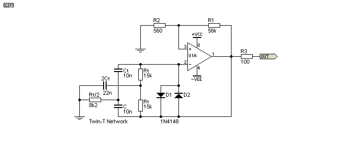
Figure 5.9 - Twin-T Oscillator
In my version shown, the twin-t circuit is deliberately slightly unbalanced, so the notch is not as deep as it would be if the values were exact. Perhaps surprisingly, this improves performance slightly. More importantly, it reduces component count (by two parts), making the circuit (ever so slightly) cheaper to build. Very little non-linearity is needed to stabilise the output, and a resistor can be used in series with D1 and D2. Adding as much as 47k barely changes the output level, but also has only a minor effect on distortion. As simulated, the distortion with the circuit exactly as shown is around 0.75%.
It works by ensuring that there is very little negative feedback at the tuned frequency, because of the twin-t notch filter. The frequency is determined by ...
f = 1 / ( 2π × Rt × Ct )
Normally, Rt / 2 and 2Ct would consist of 2 × Rt in parallel and 2C would be 2 × Ct in parallel. While this theoretically should improve performance, there seems little to suggest that it makes a great deal of difference. The twin-t does not lend itself to easy tuning, so it's mainly useful as a single frequency oscillator. As shown, frequency is 1.03kHz. This is less than the calculated value because 2Ct and Rt / 2 are not exactly double and half (respectively).
It's also fairly easy to make an oscillator using L/C (inductor/ capacitor) tuning, but it's not usually a viable option for audio. It was not uncommon many years ago in the valve era, but the inductor is large, heavy and will pick up magnetic fields at mains frequency. LC oscillators are best kept for radio frequency circuits, where the inductor can be physically small and air-cored. Because this approach is not suited to modern audio applications, LC oscillators are not covered here.
There are several different topologies for L/C oscillators, and amplitude stabilisation is often achieved purely due to the limits imposed by the supply voltage. Fairly low distortion is possible with a high Q inductor, but variable frequency is irksome. Variable inductance is possible of course, but requires mechanical linkages that are usually too difficult to fabricate accurately. Variable capacitance is not viable for audio L/C oscillators because the capacitance is small so the inductance must be very large, and it will pick up unacceptable amounts of mains frequency noise.
L/C oscillators remain common in RF applications, but even there they are often replaced by ceramic resonators, quartz crystals, frequency synthesis, or even MEMS (micro electro-mechanical systems) dedicated oscillators. The inductor is never a major problem at RF, because the inductance needed is small, and they are often used with a small ferrite slug (for tuning) and many are air-cored. These small (physically and electrically) inductors don't pick up appreciable hum, and it's so far away from their operating frequency that it will usually have no influence at all. The capacitance needed is also small, so tuning is not difficult, and the range needed is much smaller (comparatively speaking) than for audio. Audio covers a range of ten octaves, but RF tuned circuits rarely cover more than one octave, and usually much less.
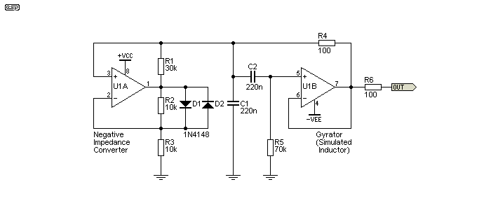
Figure 6.1 - NIC + Gyrator Oscillator
The circuit shown above utilises a NIC (negative impedance converter, U1A) and an L/C oscillator based on a gyrator (U1B). The 'inductance' is created by the gyrator, with C1 in parallel. That creates a parallel tuned circuit, which has maximum impedance at resonance. Working the values, the inductance is (approximately) equal to R4 × R5 × C2 (1.54H). Resonance is ...
f = 1 / ( 2π × √( L × C )) = 273Hz
When simulated, the frequency was 276Hz, so it's within acceptable limits. However, the circuit is difficult to tune, and a small change in the effective Q of the gyrator or the negative impedance created by the NIC will cause excessive distortion or no output. Distortion (as simulated) is surprisingly low, being less than 0.2% - this isn't wonderful, but it's not bad considering that the amplitude is limited only by the diodes in the NIC circuit. Output level is around 620mV peak, or 440mV RMS. The impedance of the NIC is nominally -30k, set by R1. This particular NIC circuit is one of the most common you'll come across, but this is the first time I've seen it used as anything other than a curiosity. The two diodes limit the negative impedance region and thus the amplitude of the oscillation.
It works because a negative impedance is inherently unstable, and when connected to a tuned circuit (C1 plus the gyrator inductor) it will oscillate. Many years ago, tunnel diodes (which have a negative impedance region) were common for RF oscillators, requiring only the diode, tuned circuit and a low voltage power source. While tunnel diodes were moderately common in the 1960s and 70s, they are much less so today. If you want to know more about them, a web search will provide many circuits and explanations.
This is an interesting circuit, and readers may well find it to be useful. It uses two rather 'off-the-wall' concepts, the NIC and the gyrator. These are both fascinating and obscure, although the linked articles on the ESP site are dedicated to the two circuit ideas. The 'common' NIC shown above is seen all over the Net as an example of how to build a NIC, but working examples are hard to come by.
The circuit shown is a simplified version of one sent to me by Steven Dunbar, AD0DT.
Diode waveform shaping is very common with low cost analogue function generators (it's inside the IC itself in most cases), but the lowest distortion that is typically available is around 1%, although as low as 0.25% is claimed in some literature. The input signal is a triangle waveform, and the diodes progressively clip the peaks to give a reasonably smooth sinewave. Although the distortion is usually audible, it is still usable for simple signal sweeps, for example to find the resonant frequency of a speaker. There are countless different diode clipping schemes on the Net, and the one shown below is purely an example.
Triangle waveforms are very easy to generate with simple opamp circuits, and that makes it attractive for low-cost function generators.
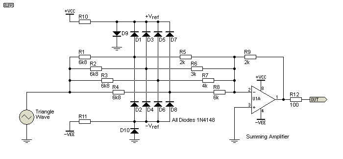
Figure 7.1 - Waveform Shaping Example
In the example shown, a ±6.6V triangle wave input gives the lowest distortion. Because of the different impedances in each of the 4 clipping circuits, the output amplifier sums a variety of clipped and un-clipped waveforms, with the end result looking rather like a sinewave. It is very important that the triangle waveform is perfectly symmetrical, or even-order harmonic distortion rises rapidly.
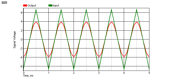
Figure 7.2 - Waveform Shaping Input And Output
The distortion on the output is about 1%, which is fine for basic tests, but is obviously useless for measuring distortion. It's generally not mentioned, but the output waveform will typically have more higher order harmonics than low order. For example, a FFT plot of the output shows a little 3rd harmonic (at about -58dB), but over 10dB more 5th (-42dB), 7th (-46dB) and even 6dB more of the 9th (-51dB). A basic filter can get THD below 1%, but it's hard to improve on that without additional complexity. This method is suitable for integration, but as a discrete circuit there's too many parts for a rather poor end result.
Note that the output was inverted so the direct relationship can be seen (the circuit shown inverts the output signal).
Another option is to use a logarithmic amplifier. While this is theoretically better than diode clipping, in reality there's usually very little difference between them. Unless proper temperature controlled log ICs are used there will usually be a small change in amplitude and distortion as the ambient temperature changes - this applies to diode shaping as well, although the effects are likely to be less severe with the simpler diode clipping circuits.

Figure 7.3 - Improved Sine Approximation
By using a transistor differential pair, it's possible to synthesise a triangle wave into a respectable approximation of a sinewave [ 13 ]. The two transistors must be matched and in close thermal contact with each other. The circuit's been simplified, showing a current source for the emitters, but this needs to be made using additional transistors. Power to the opamps is not shown. Note that the output impedance of the triangle wave generator must be as low as possible (an opamp buffer is recommended).
The circuit as shown is capable of less than 0.2% distortion, which is considerably better than that obtained using the diode clipping circuit shown in Figure 7.2. The reference document contains the formulae for calculating the values, which are quite critical. The amplitude of the triangle waveform must be exactly ±1V for best performance. A deviation of only 100mV causes the distortion to rise dramatically. The requirement for odd value resistors (E48 Series, 48 values per decade) is limiting, and most hobbyists won't have them in stock. Most hobby suppliers only stock the E24 Series, and some don't even go that far.
Digitally generated sinewaves are becoming much more common than they once were, but most have a limited bit depth which limits the usefulness of such techniques. I would suggest that anything less than 8 bits is completely useless, because distortion will be too high. Eight bit resolution gives a theoretical distortion of 0.5%, and this is halved for each additional bit used. Two techniques that reduce distortion are the addition of a filter (preferably tracking) to remove the harmonics, and adding dither - essentially random (white) noise - at a very low level. For serious work, nothing less than 14 bits is really much use, as distortion is still too high unless post-filtering and dithering is used. A 14 bit system should be able to provide distortion below 0.01%.
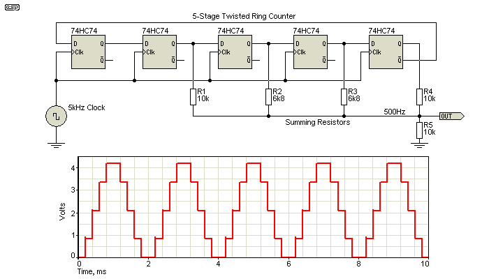
Figure 8.1 - Digital Sinewave Generation
The above is an example of a digitally generated sinewave. The output frequency is 1/10th of the input (clock) frequency. In the example shown it's limited to 5 bits, so while the theoretical distortion is 4%, this can only be achieved if the signal is filtered. More aggressive filtering will reduce the distortion. With a 220nF cap in parallel with R5, distortion is reduced to a little over 2%. This type of generator can only be used with a tracking filter as described in a Silicon Chip magazine article that had a design for a complete system. However, in the SC article, the values of R2 and R3 were wrong - they were specified as 16k, but this makes the distortion a great deal worse than it should be.
With some further experimentation, it turns out that a 4-stage twisted ring counter may actually provide lower distortion than the 5-stage version shown, despite theory saying otherwise. Certainly the unfiltered distortion of the 5-bit version is lower, but after filtering the difference is significant. If you use a 4-stage ring counter, the 2 × 6k8 resistors have to be reduced to 3k9. Ultimately, it all depends on the filter that's used to remove the clock frequency. Normally, it's suggested that the outputs should be taken from n-1 counters (where n is the number of flip-flops). A 4-stage twisted-ring counter violates that rule, but gives a better result!
Calculation of the resistor weightings used to approximate a sinewave is not as straightforward as one might hope. I've seen a couple of papers on the subject [ 14, 15 ] and they are quite different. The values shown above were not calculated, but were determined empirically to obtain values that gave the lowest (unfiltered) distortion. With a 5-stage counter, the unfiltered output has a (wide band) distortion of about 18%, and the output filter (not shown) cleans that up. Around 0.1% THD is possible with only an 18dB/ octave low-pass filter, tuned to the frequency being generated.
A viable option for digital sine generation is to use the sound card in a PC. There are several freeware and shareware programs available on the Net that will generate sine, square and triangle waveforms. With 16 bits and 41.4kHz or more sampling rate, the distortion should be very low, but it depends on your sound card. Most modern audio analysis and measurement sets use digital processing throughout, typically using 24 bits and a 196kHz sampling rate. Some (especially the very expensive kind) may use higher resolution and/ or a higher sampling rate.
The analog Devices AD9833 is one option for a programmable sinewave generator, but it requires a micro-controller to tell it what to do, and has only 10 bit resolution. While this is certainly a viable solution, the IC itself is only available in a SMD (surface mount) package, and when you add all the support devices (including a display screen so you know the settings) it becomes a fairly major undertaking.
Throughout this article, I have used variable resistance (potentiometers) as the frequency control device, but these have known issues that limit their usefulness. While there are some very good quality wirewound pots that would be suitable for long-term reliable use, these are not commonly available with high values or in dual-gang configurations.
Commonly available (cheap) pots have poor tracking, and that increases amplitude bounce as the frequency is changed. As the pot wears, there will also be small 'dead spots' caused by minute gaps in the contact area as it gradually wears away. Dust can also cause dead spots. Anything that disturbs the tracking causes the amplitude stabilisation network to work that much harder, and amplitude bounce is extremely annoying when carrying out many common tests.
One common fix for this is to use (old AM) radio type tuning gangs - variable capacitors. Because the plates mesh together without ever touching, there is no wear, although bearings can fail if the instrument is heavily used. I have a number of pieces of test gear that use variable capacitors, and have never had a failure of any kind. Meanwhile, I have replaced pots several times in other equipment.
There is no doubt that the variable capacitor is by far a better control system, but it too has its problems. Most importantly, the capacitance is low, usually around 100-500pF. This means that circuit impedances are high - for 20Hz at 500pF, you need resistors of 15.9M ohms. Small amounts of stray capacitance cause major problems, and the likelihood of hum pickup is greatly increased.
In addition, all amplifiers used (whether discrete or opamp) must have FET inputs because of the very high impedances involved. However, nearly all of the circuits shown above can use a variable capacitor for tuning, and for different ranges the fixed tuning resistors are switched. Some more recent oscillators (Chinese origin) use variable caps that have higher than normal capacitance. This is achieved by using a plastic dielectric film between the plates, thus increasing the capacitance but at the expense of thermal stability.
If possible, use conductive plastic pots for tuning. They are considerably more expensive and harder to get (especially dual-gang types), but they offer better tracking and more stable performance over time than 'ordinary' carbon pots. Dual wirewound pots in the values needed (typically 10 to 20k) are now virtually impossible to obtain.
The choice of opamps, and capacitors depends on your expectations. If you use a diode clipping circuit to stabilise an oscillator, then quite obviously choosing expensive, low distortion opamps would be silly. Likewise, it would make no sense to use expensive capacitors either, since their contribution to overall distortion is far lower than that of the clipping network. It would be equally silly to use high quality opamps and amplitude stabilisation, then use high-k ceramic capacitors which have dreadful (and often easily addible) distortion.
If you intend to optimise the circuit, then you must select opamps with vanishingly low distortion (they will be expensive). You also need to choose the topology carefully to minimise common-mode distortion in the opamps. Capacitors will ideally be polypropylene for lowest distortion and minimum thermal drift. Low value caps should be G0G (aka NP0) ceramic types. Polystyrene is also good, but you might want to avoid silvered mica. None of these suggestions will affect audible distortion one way or another, but for a measurement system it's critical to have the cleanest possible waveform so the final measurement does justice to the device being tested.
All resistors should be metal film, as they are quieter and more stable than carbon types. Avoid carbon composition resistors, and ideally avoid all carbon resistors unless they are in non-critical parts of your circuit. The power supply (whether single or dual) needs to be well regulated and fairly quiet (particularly single supplies). Project 05 is a good choice.
The final circuit needs to be in a shielded metal box to prevent mains hum and RF pickup. Both can ruin an otherwise perfectly good distortion measurement. In common with nearly all commercial test equipment, I suggest that outputs should use BNC connectors. Since this is not a project/ construction article, the details of yow you build the circuit are up to you. Apart from these few tips, no further construction advice can be provided.
While I've concentrated on variable frequency oscillators, in some cases it's easier to use a number of single-frequency oscillators. These are much easier, because there's no need for 'excess' gain and subsequent problems with stabilisation. Each oscillator can be optimised for just one frequency, and distortion can be reduced to almost nothing with a high-Q filter. The two-opamp gyrator described in Project 218 is a good candidate. I use two filters tuned to 400Hz and 1kHz that remove the distortion from my digital waveform generator, with it well below my measurement threshold.
It's not difficult to get a distortion reduction of more than 100, so 0.5% distortion is reduced to 0.005%. While this is alright for many applications, it's still not good enough if you wish to characterise an ultra-low distortion opamp circuit or a high-quality DAC. You can use two filters in cascade, and this will improve the distortion more, at least until the opamps used in the filters become the dominant source of distortion and/or noise.
In conjunction with an oscillator with reasonably low distortion to start with, it should be possible to get a total distortion of less than 0.0001% (-120dB). there are a few very/ ultra low distortion oscillators described on the Net, including Project 174 which was contributed in 2016. This is a spot-frequency oscillator, and it's not suitable for continuously variable operation. The choice of capacitors is very limited when you need extremely low distortion, and the ideal dielectric is either polystyrene or NP0 (aka G0G) ceramic.
Spot-frequency oscillators are not at all uncommon when the highest performance is desired. It does mean that you need a separate oscillator for each test frequency, but there are few alternatives. The 16th reference is a well-known design that claims distortion below -140dB. While you need multiple oscillators, it's not particularly expensive to implement (other than polystyrene caps which are fairly hard to get with few available values and they're comparatively expensive).
Very low distortion may seem like a requirement in all cases, but it's no. There are oscillators that are designed specifically to have extremely good level control (so it doesn't change as the frequency is altered). Because these need very fast level correction to maintain the output voltage at the desired level, something else has to suffer. This is almost always distortion. An example is the HP 208A oscillator. This design has almost perfect level control, with the output voltage remaining steady over the full frequency range. As the frequency is changed (using a high-precision dual pot), the level doesn't change by more than 0.125dB.
To get this degree of amplitude accuracy, something else has to suffer. Distortion is quoted as "less than 1%", which is not wonderful, but 'adequate'. To get the best possible settling time, the peak detector (that controls amplitude) has different capacitor values for each frequency range. Each is designed to provide the fastest amplitude response based on the frequency range in use. Most other sinewave oscillators use a long time-constant for the amplitude control to get low distortion.
A reasonable approach is ...
Amplitude Stability/ Fast Settling/ Low Distortion Pick any two!
If you need low distortion, you almost always have to accept either mediocre amplitude control or long settling times. It is possible to have all three, but the circuit becomes very complex, and the tracking of the control element (variable resistance or capacitance) has to be close to perfect! Common dual gang pots have poor tracking, and almost invariably cause amplitude 'bounce' or momentary drop-outs. For looking at frequency response (for example), you need (close to) zero amplitude bounce or dropouts, but distortion is not a major issue provided it's less than ~2% or so.
Function generators using 'sinewave shaping' (see Section 7) are very good in this respect, and there is zero bounce. Amplitude stability is temperature dependent though, but for most tests that's not a major problem. A typical test will be fast enough that thermal drift won't cause any amplitude variation.
Based on the information in this article, you should now be able to build yourself an audio sinewave generator. They are not simple, and obtaining vanishingly low distortion is a serious challenge for all techniques, both analogue and digital. The one component that made a low distortion oscillator a comparatively simple project - the RA53 thermistor - is now gone. Apart from a few old buggers like me who've managed to squirrel a couple away over the years, they are virtually unobtainable. Small lamps do work surprisingly well though, and this remains a viable option. You must ensure that the lamp voltage is at least 10% of the rated voltage. For example, a 28V lamp should be operated with at least 2.8V RMS across the lamp itself, and preferably a bit more. If this isn't done, continuous amplitude bounce may occur with some lamps.
Although I have shown that the lamp will work, they are less predictable than the thermistor unless you have a reliable source. More complex techniques using FETs or LED/LDR optocouplers may often be needed, but most are unable to get distortion figures that even approach the thermistor or lamp. Eventually, all audio oscillators will probably be digital, because the analogue techniques are getting too hard. Even finding a good quality dual-gang pot with accurate tracking between the sections is difficult - once, high value wirewound pots were made that were perfect, but these too have all but vanished.
To be able to take distortion measurements, the easiest approach will almost always be to use a general purpose audio generator followed by a low-pass (or band-pass) filter. This can be made switchable, so you can have a few spot frequencies for distortion measurements, but still have the ability to sweep the signal over a wide range. The filter will reduce the level of harmonics, and would normally be built so that the -3dB frequency of the filter corresponds to the measurement frequency or slightly below (amplitude will be reduced). For most applications, a 12dB/octave (second order) filter will be sufficient, and will reduce distortion by a significant amount. Naturally a higher order filter will reduce the distortion further. In a test that I ran, initial distortion was fairly high - almost 0.7%. A 12dB/octave filter reduced this to 0.2% and a 24dB filter reduced it further to 0.06%. Naturally, if you start with a distortion at an already sensible value (around 0.02% or so), a 24dB filter will get you to perhaps 0.002%.
Ultimately, you will quickly run out of distortion signal and be left only with noise. Even here, the filter helps a lot, because all noise above the test frequency is filtered out. With a much narrower bandwidth, noise is diminished significantly.
As I hope is now very clear, sinewaves are not simple. They are without doubt the hardest signal to generate accurately (i.e. with minimum possible distortion), and I hope the information presented gives you a few new ideas. There are countless circuits, academic papers, discussions (between engineers and some hobbyists) and forum posts on the Net, with many discussions of stabilisation techniques and the optimum topology overall. If (as many 'audiophools' insist) "sinewaves are simple" then none of this would be necessary. Alas, it is the very 'simplicity' of sinewaves that makes them so difficult to produce. A single frequency, with no distortion or noise is, in fact, an impossible dream !
Despite all the advances in electronics over the years since Hewlett-Packard started building Wien bridge audio oscillators in a converted garage, this still remains one of the best overall topologies. To be able to get the wide range of frequencies needed for response measurements, we still need to use discrete circuits. Few (affordable) opamps have good enough high frequency response at full level - we need at least 100kHz, preferably more.
While the oscillator itself is not difficult, the downfall of almost every circuit is the stabilisation technique. There is no perfect method, the simple ones have either disappeared or are in the process of doing so (vacuum NTC thermistors and small incandescent lamps respectively), and eventually the stabilisation circuit ends up being vastly more complex than the oscillator. There are many circuits on the Net that manage that, as does Project 174. Unfortunately, there are few options, and it's getting even worse as the number of JFETs continues to shrink as well.
For what it's worth, the audio generator I use the most now is a digitally synthesised function generator, which includes sine, triangle and square waveforms, dual oscillators (which can be synchronised), tone burst facilities, a sweep generator, arbitrary waveform generation, plus a great deal more. It's very flexible, but it's also less convenient than a standard analogue oscillator for some applications. Residual distortion is 0.02%, so it's (just) good enough to be able to take distortion measurements on most equipment. However, a 'traditional' analogue oscillator is much more user-friendly for many tasks, and there is still a need for a simple oscillator with distortion below 0.1%.
For most hobbyists, I would not recommend a digital function generator, as it's far more than is necessary for most testing and they aren't as convenient as a normal audio oscillator. I needed it because of work I've been doing that involves very low frequencies (0.1Hz or less in some cases), but that's obviously not needed for normal audio work. One design that is recommended is Project 86, which uses the technique described in Section 6.5 in this article. It's not perfect, but it does perform surprisingly well. As noted above, there's also a PCB available, which makes it very easy to build.
While many of the circuits shown here have been built and tested, many others are simulated. Unfortunately, the simulator I use doesn't include a non-linear resistor, so lamp stabilisation was tested on the workbench for most (but not all) lamp stabilised circuits shown. JFET circuits were simulated, and LED/LDR circuits were also bench tested (the simulator doesn't have an LED/LDR optoisolator either).
1 - Thermistors, lamps, LED/LDR Stabilisation Techniques, Linear Technologies Application Note, AN43
2 - Easily Tuned" oscillator - National Semi Linear Brief, LB-16, 1995
3 - Sine-Cosine Oscillator (massmind.org) - (Note that JFET is not connected properly, so expect more than 'normal' amplitude bounce.)
4 - Intersil Application Note AN1087, March 20, 1998
5 - Sinewave Generation Techniques, National Semiconductor Application Note, AN-263, 1999
6 - Design of Opamp Sinewave Oscillators, Ron Mancini, Texas Instruments Application Note
7 - Wien Bridge - Classic circuit, multiple sources (including several above).
8 - Wien-Bridge Oscillator With Low Harmonic Distortion, J.L. Linsley-Hood, Wireless World, May 1981
9 - Sine Wave Oscillators, Ron Mancini and Richard Palmer (SLOA087, Texas Instruments)
10 - A Quick Sine Wave Generator (SNOA839, Texas Instruments)
11 - Sine-Wave Oscillator (SLOA060 - Texas Instruments)
12 - Sine-Wave Oscillators (SNOA665 - Texas Instruments)
13 - till.com - An Improved Sine Shaper Circuit
14 - Digital Generation of Low-Frequency Sine Waves (Anthony C. Davies, Member, IEEE, June 1969)
15 - Create Sinewaves Using Digital ICs (Don Lancaster, American Radio History, November 1976)
16 - An ultra low-distortion oscillator with THD below -140 dB - Vojtech Janásek
Recommended Reading
Designing With Opamps - Part 1 and Part 2 - ESP
 Main Index
 Articles Index