

|
| Elliott Sound Products | Project 218 |
A number of ESP projects have used gyrators (simulated inductors), but the one described here is different. It can be made to have a very high Q ('quality factor'), providing a very sharp filter response. There aren't many audio applications that require sharp filters, but of course the term 'audio' doesn't limit anyone to stuff you'll listen to. Anything that's operated within the audio spectrum qualifies. For instrumentation, the range can cover anything from DC up to around 40kHz, although you need fast opamps to get anything useful at more than 15kHz or so.
This project is adapted from the Gyrator Filters article, and is capable of much higher Q than most other opamp-based bandpass filter circuits. It's also quite stable, and only needs a dual opamp for each filter frequency. It has a low-impedance output, and the individual outputs of a number of filters can be summed to obtain the final result.
One thing that sets it apart from more 'traditional' bandpass filters is that it doesn't require complex calculations or multiple odd-value components to set the frequency. So, while it uses more parts than a multiple feedback (MFB) bandpass filter, it's also far easier to tune. The circuit can be configured as a simulated inductor, but it's not particularly useful in that role. The primary reason to use it is as a bandpass filter. Unlike a more conventional gyrator, it cannot be converted into a band-stop (notch) filter, so it's far more limited. This is more than compensated for by its performance.
While I've used the term 'gyrator' in this article, the circuit is probably better described as a 'generalised impedance converter' (GIC) which itself is based on a 'negative impedance converter' (NIC). Like most circuits that employ negative impedance, it has a potential issue with DC stability. The circuit simulates perfectly, with no output DC at all, and interestingly reality is no different. In use, the circuit should have a DC coupled input, but (and perhaps surprisingly) it biases perfectly regardless of whether the first opamp (U1A) has a zero-volt reference or not.
The filter shown here is something of a mystery. I became aware of it from a circuit sent to me by a friend, and it has some significant advantages over the more common versions of gyrator or multiple feedback filters. In particular, the output impedance is low (nominally zero ohms), and it can be made to have a very high Q, with comparatively low component sensitivity. There is no internal gain which could cause premature overload (clipping), but the tuning formula is a bit odd. I could find no 'official' formula (and no information other than in the referenced document [ 12 ]), but I was able to work out a formula with a 'fudge factor' (aka a 'constant') that has proven to be accurate.
The value of 5k is the 'constant' that applies when R3 and R4 are both 10k. If you wanted to be adventurous, it's the parallel combination of R3 and R4, so you can make them different if you like making things harder for yourself. In general, R3 and R4 should be the same value for best performance. The parallel combination of two 10k resistors is (of course) 5k. R3 determines the gain, which is nominally 6dB with the values shown. It also affects the Q, but in a way that isn't predictable without resorting to complex formulae. If R3 is made much smaller than R4 (6.8k for the circuit as shown) the circuit will oscillate!
Reducing R3 also increases the internal gain of the circuit, making it much easier to cause clipping. Because U1 is a negative impedance circuit (NIC), resistor value changes can have 'unexpected' consequences. The original design used equal values for R3 and R4, and this really is the optimum combination.
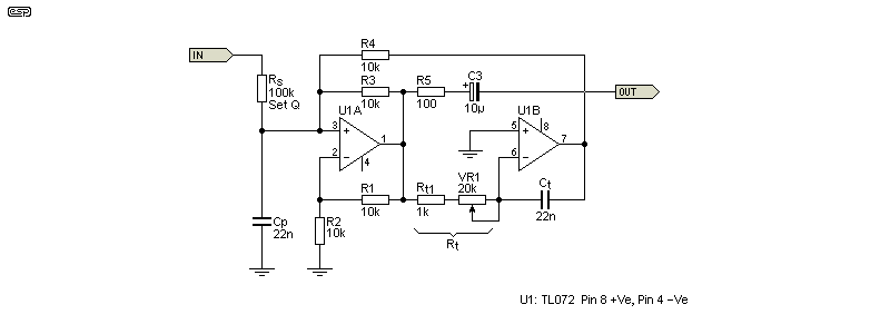
Figure 1 - Two-Opamp Gyrator Based Bandpass Tuned Circuit
With values as shown for R3 and R4 (10k) and Rt (Rt1 + VR1) set for 10k in total, the inductance is determined by ...
L = Rt × Ct × ( ½R4 )
L = 10k × 22n × 5k = 1.1H
There's no requirement for R1 and R2 to be the same value as R3 and R4, but there's also no reason to make them different. The formula shown has been tested against a large number of filters in the referenced document (the published schematic uses 40 individual filters!). I've also run many simulations to verify inductance, resonant frequency and Q, with consistent results. Naturally, I encourage the constructor to experiment, either with the 'real' circuit or a simulation.
Note that the Figure 1 circuit is a bandpass type when Cp is added, and it cannot be rearranged to form a band-stop (notch) filter. Without Cp it performs like an inductor, having zero output at DC and an impedance that rises at 6dB/ octave with frequency (as expected). With Cp included as shown, Ct as 22nF and Rt set for 10k, the resonant frequency is 1,023Hz ...
f = 1 / ( 2π × √ ( L × C ))
f = 1 / ( 2π × √ ( 1.1 × 22nF )) = 1.023 kHz
Or using a single formula ...
f = 1 / ( 2π × √ ( Rt × Ct × ( R3 || R4 ) × Cp ))
f = 1 / ( 2π × √ ( 10k × 22n × 5k × 22n )) = 1.023 kHz
Thanks to some info from a reader, there is another way to look at the circuit ...
The circuit can be considered as a modified Howland current source (aka current pump) driving an integrator. The circuit is somewhat rearranged though, as the output from a Howland source is generally taken from the non-inverting input (U1A pin 3), which is used as an input from the integrator. This means that there's still an air of 'mystery' surrounding the circuit. This is doubly true since I've not seen it mentioned anywhere other than the second reference ('String Filter'). There's another way of looking at the circuit, as U1A can be classified as a negative impedance converter (NIC). See Negative Impedance for a detailed discussion of this topic. Figure 7 of the article shows a NIC gyrator that's very close, with the difference being that the integrator is passive, where the circuit described here uses an active integrator.
As a bandpass filter, it uses more parts than a MFB (multiple feedback) filter, but it's far more versatile and easier to tune. The frequency can be changed by altering Rt with a pot, and Q is independently adjustable by varying Rs. While it uses twice as many resistors and opamps, that's more than compensated for by the high (and easily adjustable) Q available, and the ease of wide-range tuning.
Note that the formula shown assumes exact values for R1 ... R4. Even with a variation of only 1% (standard metal film resistors) the Q and circuit gain will change. Also, be aware that the circuit has gain (nominally 6dB), and there's also internal gain of another 6dB (×2), with the output pin of U1B (up to) four times the input voltage. Even small resistor tolerances will affect this though, so you must run some tests of your own.
With any bandpass filter, determining the Q is generally needed. It's not hard, but providing a single formula isn't likely to be helpful. The first task is to determine either the capacitive reactance (XC) or inductive reactance (XL). At resonance, they are equal, so I'll use XC ...
XC = 1 / ( 2π × f × C )
XC = 1 / ( 2π × 1,023 × 10n ) = 7.071 kΩ or ...
XL = 2π × f × L
XL = 2π × 1,023 × 1.1 = 7.070 kΩ
The small difference between the two impedance calculations is simply the result of not using all decimal places, and is not an error. The Q is simply (and approximately) the series resistance (Rs) divided by XC or XL, which works out to be about 14.14. The calculation will almost always be a little different from the measured value, but bear in mind that actually taking a measurement with any degree of accuracy is very difficult with high-Q filters. I measured the Q (using the simulator) to be 14.41, so the error is small, and for almost all applications it's insignificant.
Q = Rs / XC or
Q = Rs / XL or
Q = f / BW Where 'BW' is -3dB bandwidth
Once you get a filter with a Q of more than 20 or so, the bandwidth becomes very narrow, so (for example) a 1kHz filter with a Q of 20 has a bandwidth of only 50Hz. That works out to be from 975Hz to 1,025Hz. One of the things that always seems odd is that when a gyrator is made variable, the bandpass filter Q increases as the frequency is increased. Since Q depends on the reactance of the inductance and capacitance (they are equal at resonance), as the frequency is increased, the reactance of the two components falls, so Q increases for a given series resistance.
For most applications, it's easiest to keep Cp and Ct the same value. If they are changed without changing anything else, the filter Q remains constant, but of course the number of frequencies is limited. The table below shows the frequencies you can get in one decade (with Rt kept at 10k). For frequencies below those shown, simply multiply the capacitance shown by ten, and for frequencies above, divide the capacitance by ten. For example, 1µF will provide a frequency of 22.5Hz, and 1nF will increase the maximum to 18.57kHz.
| Cp, Ct | 100n | 82n | 68n | 56n | 47n | 39n | 33n | 27n | 22n | 18n | 15n | 12n | 10n |
| f (Hz) | 225 | 274 | 330 | 402 | 478 | 577 | 682 | 834 | 1,023 | 1,250 | 1,500 | 1,873 | 2,250 |
| Ideal¹ | 225 | 273 | 330 | 400 | 485 | 587 | 712 | 862 | 1,044 | 1,265 | 1,532 | 1,857 | 2,250 |
Using all values from 10nF to 100nF gives the frequencies shown above. It would be nice if they followed the musical sequence (¹/12th root of 2, or 1.05946) but's probably too much to ask for  . There is rough correlation with the basis for the E12 sequence used for resistors and capacitors, shown as 'Ideal' and based on the ¹/12th root of 10, or 1.2115. This would divide a decade into 12 (more-or-less) logarithmically spaced intervals. There's probably not much point unless you are building a frequency analyser or perhaps a vocoder. Both are fairly unlikely due to the number of filters necessary.
Using a larger cap for Cp and a smaller one for Ct reduces the impedance for a given Q, so Rs can be a lower value. This is shown in Figure 4, but it gets messy if you need lots of filters because they don't follow the 12th root of 10 properly, so Rs also needs to be changed to get the desired Q. This isn't difficult, but can become irksome. If you only need a single filter then it's no longer an issue.
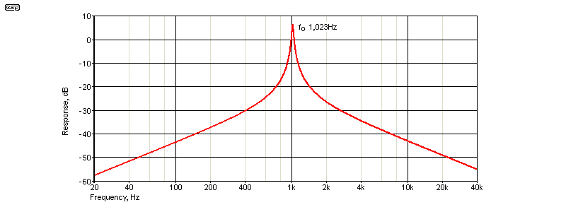
Figure 2 - Bandpass Tuned Circuit Frequency Response
The response is shown above, with Rs set for 212k, giving a Q (as simulated) of 30. To give you an idea of what that can do, if fed with a 1.023kHz squarewave the distortion at the output is reduced to 0.4%. Considering that a squarewave starts with a distortion of 48% ¹, that's not a bad start. With two identical filters in series, the distortion is reduced to 0.006%, which is impressive. If you start with a reasonable sinewave (from an 'ordinary' oscillator having around 1% THD for example), it's possible to obtain a very pure waveform with a single filter that can be used for distortion testing.
¹ The distortion of a squarewave can be calculated as √(( π² / 8 ) - 1 ) [ 3 ]
The next decision you have to make is the selection of the opamps used. If your goal is to obtain a pure sinewave for distortion testing, you need an opamp with good distortion specs. The NE5532 might seem like a good idea, but DC offset will become a real problem. I experimented with a few opamps, but the TL072 won out over the others with the least DC offset. The performance was very good, reducing the THD of my function generator from 0.023% to well below my measurement threshold. If you start with a sinewave, a single filter is all that's needed.
Some changes may be needed if you wish to use any BJT input opamp, because they don't have exceptionally high input impedance. Consequently, it may be necessary to change the capacitance to a higher value and the simulated inductance reduced to lower XL and XC, allowing Rs to be a lower value for the desired Q. This can get unwieldy though, so for initial tests I suggest that both capacitors should be the same value.

Figure 3 - Two-Opamp Gyrator Based Bandpass Tuned Circuit With Explanations
The above drawing was included to show the significance of each component. The interactions are complex, and a detailed explanation is not included here. Many of the parameters are very sensitive to component variations. Even using 1% tolerance resistors, you will see variations of gain and Q in a real circuit. A simulator has ideal parts, and real-world tolerance will change the parameters. While it's certainly possible to use trimpots (or parts selection) to get accuracy better than 0.1%, it's usually not necessary to go to such extremes.
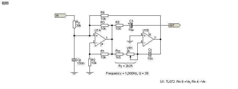
Figure 4 - Optimised 1kHz Bandpass Filter
The Figure 4 drawing shows an optimised filter, designed to allow high Q with a relatively low value for Rs. By making Cp larger and Ct smaller (as well as Rt), the impedance of each reactive element at resonance is lower, minimising any effects of stray capacitance. The ratio of 10:1 is arbitrary, but is a good overall compromise for this circuit. VR1 allows the frequency to be trimmed. This circuit will become part of my test setup, allowing me to use a function generator but still get distortion at 1kHz well below 0.01%.
It's one thing to simulate a circuit and get all excited, but it's something else again to see it on a scope, and observe the level fall by 15dB with a 10% frequency change (from 1kHz, down to 900Hz or up to 1.1kHz). The distortion from my function generator is around 0.023% and is normally a limiting factor for distortion measurements, but not with the Figure 4 filter in circuit. The distortion is reduced so much that all that's left in the residual (available via a connector on the meter) is some of the 1kHz fundamental, and a few stray harmonics that I'm pretty sure are generated by the distortion meter itself.
I didn't select any of the parts, but used them out of the box. Resistors are all 1% metal film, and capacitors are ordinary MKT polyester types. The trimpot allows adjustment so that capacitor tolerances (in particular) are easily compensated. The result is impressive, and testing with another distortion meter gave a similar result, with distortion below anything I could measure. I expected a good result, but this exceeded my expectations.
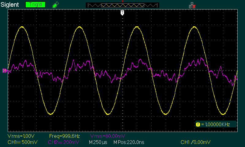
Figure 5 - Optimised 1kHz Bandpass Filter Waveforms
The distortion measured is in the order of 0.007%, but the meter isn't calibrated below 0.01%. The main objective was to see just how good the filter was, and the result is pretty clear. I tested it with several different opamps, but the TL072 is the best choice overall because it has the lowest DC offset thanks to its JFET inputs. While it might be bettered by more esoteric devices, it's apparent that once the distortion is well below one's measurement threshold there's no point aiming for less.
Be aware that the circuit uses a combination of negative and positive feedback, so opamp input current is amplified and may cause a DC offset. Using an opamp with very low input current helps to ensure that any DC offset is kept to the minimum. I tested my circuit with several different opamps, and (to my surprise I must admit) found that DC offset was minimal. The output capacitor may need to be reversed depending on whether the offset is positive or negative, but only if it's greater than ±100mV.
The theoretical Q of the Figure 4 circuit is 37 and I measured it at just under 28. While this seems like a large discrepancy, it makes surprisingly little difference to the end result. No matter which opamp I used, the output distortion remained resolutely below my measurement threshold, and that included a 1458 (basically a dual µA741). The TL072 remains my preference though, because of its very low input current and overall performance.
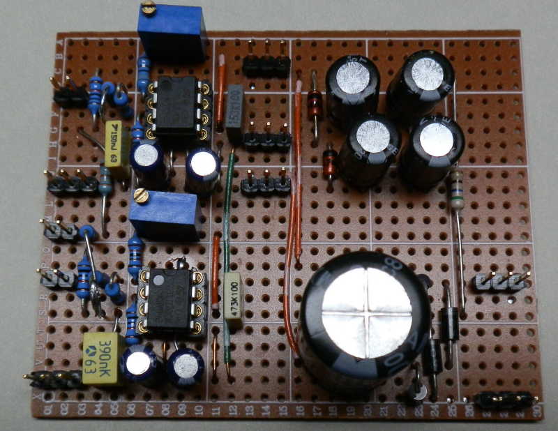
Figure 6 - Photo of Prototype 1kHz + 400Hz Filter With PSU
My completed unit is shown in the photo. There are two filters, and an on-board linear supply using zener diode regulation. This was tested thoroughly for noise and ripple, and it's very clean, despite its simplicity. I contemplated using a more sophisticated supply, but when I found that performance was unimpaired even using a switchmode supply, I decided on the simple approach.
This particular filter is unusual, firstly because it only works as bandpass type, and it has much higher performance than most others. Attempting to emulate Figure 4 with a multiple feedback (MFB) bandpass filter is possible, but involves the use of resistors that are unavailable and even difficult to create using series resistors. By comparison, the two-opamp gyrator is easily tuned over the required range (±10Hz or so is all that's needed), while the MFB topology is very sensitive to component variations.
This filter is also interesting in its own right, because it's different from other circuits that may be suggested for the same task, and it performs far better than most. Interesting circuits are good - they expand one's knowledge and add another solution to the circuit 'toolbox'. Like so many other circuits, you may never need it, but if you suddenly do find the need for an easily tuned bandpass filter, this one is well worth trying.
Using the filter to get a very clean sinewave for distortion testing turns out to be a very good idea. If you need more than one frequency, then you obviously need more than one filter, but this is hardly a major chore, and nor is it particularly expensive. The distortion meter I use the most has two fixed frequencies, 400Hz and 1kHz, so I made two filters. I now have the ability to measure distortion down to 0.01%, secure in the knowledge that the sinewave has distortion that's low enough for me to be confident in the reading.
The way I'm using it, it's only suitable for spot-frequency measurements, but that's fine with me because my favoured distortion meter only uses 400Hz and 1kHz. I also decided that it was easier to have two separate filters rather than one with frequency selection, because the filters are too sharp to allow switching without an external tuning pot. Building two filters also let me be assured that the first one wasn't a fluke - a single prototype is rarely sensible, because you'll never know if it works perfectly because the design is solid, or because component tolerances worked in your favour. This is very real, and even experienced designers have been caught out by producing just one prototype, then discovering that with different ICs or other parts the production versions don't work.
This circuit has elicited a number of responses from readers, some pretty much 'on the money' and others not so much. There have been several suggestions (particularly regarding my 'fudge factor'), but not all reflect reality. This is a very interesting circuit, and I didn't expect to find it to be truly unique. The original designer is to be congratulated for developing such an elegant design that's so easy to tune, even if analysis is far more complex than most other circuits that perform a similar function.
A popular opinion is that it's a variation on a 'Deboo' integrator, but IMO that's not the case. This integrator would have a capacitor at the R2 position, although it can also be classified as using a Howland current pump/ NIC (negative impedance converter) as the main active element. The integrator is separate in the design shown, based around U1B. There are probably several different ways the circuit can be classified, but IMO none of the suggestions made so far really apply. There are similarities to other circuits, but it's different. A reverse image search was fruitless - the same basic arrangement seems not to be found elsewhere.
The negative impedance converter (U1) really is the heart of the circuit, and these are not well understood by most engineers, and much less so by hobbyists. However, as you can see from the design itself, the NIC provides a benefit that is unmatched by more 'traditional' band-pass filter circuits. In this case, the NIC feeds the integrator (U1B) which provides feedback to the NIC. Like all 'standard' gyrators, the circuit appears to be an inductance to the outside world, meaning that it has reversed the function of the capacitor by electronic skulduggery. It behaves as a tuned circuit only because of the input capacitor, so it behaves like a parallel tuned circuit (maximum impedance at resonance).
 Main Index
 Projects Index