

|
| Elliott Sound Products | Gyrator Based Active Filters |
 Main Index Main Index
 Articles Index Articles Index
|
Gyrators (aka 'simulated inductors') are an immensely useful electronic building block, but their operation appears to be deeply mysterious. This shouldn't the case at all, but since they have been used in several ESP projects and I only touched on them in the Active Filters article, I thought it would be worthwhile to discuss them in a bit more detail.
There's another class of circuit that's commonly referred to as an 'active inductor', but it's really just a modified gyrator that generally doesn't work as well. While you might not think there's much point, in reality every circuit arrangement can come in handy, and it's a matter of selecting the circuit that does exactly what you need. There are also many articles that describe high frequency active inductors implemented in CMOS, and typically using voltage controlled current sources - these are not included here.
The gyrator was first proposed in 1948 by Bernard Tellegen as a hypothetical fifth linear element after the resistor, capacitor, inductor and ideal transformer. A symbol was also created that you may see used in some articles (but not this one). In real terms, capacitors have far fewer issues than inductors, which is to say a capacitor has a great deal of capacitance compared to resistance and inductance. On the other hand, a 'real' inductor has copious amounts of resistance, and may also have significant (distributed) capacitance. Wound inductors are also subject to variations in the core material and stray capacitance, which make them far less an 'ideal' component than even quite pedestrian capacitors.
If you are not already familiar with the concept of filters or especially opamps, it might be useful to read the article Designing With Opamps - Part 2, as this gives a bit more background information but less detail than shown here.
Filters are used at the frequencies where they are needed, so all the gyrators and filters described here need to be recalculated. In general, increasing capacitance or resistance reduces the operating frequency and vice versa. Gyrators have rather different requirements, and the component selection criteria will be described where needed.
Capacitors used in filter circuits should be polyester, Mylar, polypropylene, polystyrene or similar. NP0 (aka C0G) ceramics should be used for low values. Choose the capacitor dielectric depending on the expected use for the filter. Never use multilayer ceramic caps for filters, because they will introduce distortion and are usually both voltage and temperature dependent. Likewise, if at all possible avoid electrolytic capacitors - including bipolar and especially tantalum types.
 | Most of the gyrator and filter circuits shown expect to be fed from a low impedance source, which in all cases must be earth (ground) referenced. Opamp power connections are not shown, nor are supply bypass capacitors or pin numbers. All circuits are functional as shown. |
An ESP project that uses gyrators is Project 28, and that uses them configured to be variable. This provides functions that are difficult (and may be comparatively expensive) to implement using other filter types. Equalisers are one of the best examples of where gyrators can be used as a cost-effective alternative to other filter types.
In all but a few cases, maths is kept to the minimum possible. Over many, many years of electronics, I have found that using complex maths equations is rarely needed, and this is doubly true since simulators have become readily available at reasonable prices (or even free, but with limited functionality). All of the circuits shown will simulate well, and measured performance will be different only in that real-life components have real-life imperfections. This is especially true of opamps, which have finite input and output impedance, as well as frequency dependent gain.
All the gyrators shown here are intended for operation between DC to 100kHz, and at the top end of the frequency range very fast opamps are needed. In most cases they will only ever be used over the range of 10Hz to 30kHz, well before opamp limitations cause problems. The demonstration circuits are not suitable for RF applications, where conventional inductors are small enough (and have sufficiently low losses) that trying to synthesise them would be silly. There are applications for RF gyrators (mainly for filters), but these will not be covered.
In simple terms, a gyrator is an active impedance converter. By using a capacitor as the reactive component, the gyrator converts (or transforms) the impedance from being capacitive to inductive. Gyrators are also sometimes referred to as 'simulated inductors', but that's a bit harsh because in many cases the gyrator will be much better than the 'real thing'! Instead of using a coil of wire wound around a magnetic core, an active device - most commonly an opamp - is used as the impedance converter. This way, we can use a capacitor as the controlling element, but transform its impedance so that the circuit as a whole behaves like an inductor. An inductor will pass DC unhindered, but present an increasing impedance to AC proportional to frequency, and this gives us something to test against.
For example, an ideal 1H (1 Henry) inductor has an impedance of zero at DC, 62.83Ω at 10Hz, 628.3Ω at 100Hz, 6,283Ω at 1kHz, and so on. In reality, our 1H inductor will have significant winding resistance and because it's a coil of wire with a magnetic core, it will pick up radiated magnetic fields. In addition, there is inter-winding capacitance, and that means that it will have a 'self-resonant' frequency that may even be within the audio band. The self resonant frequency is usually outside the audio band, but not always.
By way of comparison, a 1H inductor realised with an opamp and a few passive components will have almost no self capacitance, and can be designed to have an extremely low equivalent winding resistance compared to the wound component. There is also nothing to pick up stray magnetic fields, so placement on a circuit board is not critical.
As noted in the introduction (although it should be evident already for anyone who has read the ESP design notes), it must be reiterated that gyrator based 'inductors' are almost always used only for audio frequencies, and they are generally unsuited for RF (radio frequency) work. In this context, 'audio frequency' actually means anything below low RF frequencies, and gyrators will work happily from DC up to perhaps 50kHz or so. Higher frequencies are possible, but need very fast opamps that still have lots of gain at the frequency of interest.
Because discrete gyrators are most commonly based on opamps, simulated inductors are not suitable for use in power supplies, or anywhere else where an inductor is used for energy storage (switchmode power supplies for example). Fully floating (not earth referenced) gyrators are possible, but are far more complex than the traditional types and will not be covered in this article.
Gyrators actually do have the same energy storage capabilities as 'real' inductors, but their ability to generate a flyback pulse (when current through an inductor is suddenly interrupted) is limited to the supply voltage for the opamp used. The most common use for gyrators is as filter elements, but for the most popular types even this role is limited because one end of the gyrator inductor is referenced to the system common (typically earth/ ground). In many cases, traditional active filter circuits are usually a better choice than gyrators when you just need a standard high or low pass filter.
An extremely useful characteristic is that the inductance of a gyrator can be varied over a fairly wide range, and this makes some circuits possible that would otherwise be far more complex using more traditional circuits. As with anything in electronics (or any other form of engineering for that matter), there are compromises, and whether these cause a problem or not depends on the application. Just like real inductors, gyrators are not perfect, but they can be made with far fewer imperfections than a coil of wire. This is very handy.
You may see gyrators referred to as an 'FDNR' network. This means 'frequency dependent negative resistance', and is true of a particular form of gyrator that uses two opamps and one or two capacitors. These are potentially interesting, but are quite complex and are useful only in specialised applications. They are outside the scope of this article, and won't be covered here (well, actually they will, but only briefly).
One thing that is interesting but completely pointless - you can replace the capacitor in a gyrator with an inductor, and the circuit will behave just like ... a capacitor. This works, provided that you have access to ideal inductors but are short of low performance capacitors. If this is the case, then technology is your friend, and you can create very ordinary capacitors using a really good inductor and an opamp. Or you could just use a capacitor and live with the fact that it's performance will be much better than one you can build with an impedance converter (aka gyrator). If you don't believe that this can be possible, I encourage you to try it, either with a simulator or in a circuit you can build on a breadboard.
All of the circuits described here work, and can be built, with the possible exception of the circuit shown in Figure 8.2. Even that will work if you build an opamp that can run from ±100V supplies. The others are completely conventional, and it's very educational to build one so you can fully appreciate the versatility of gyrators in general. I have deliberately avoided the more complex versions that you might see elsewhere, since they offer no real benefits for normal audio frequency applications. I have also avoided all purely theoretical gyrators (those that cannot be built using real parts).
Audio frequency does not mean audio in the hi-fi sense. It simply means that the circuits are designed to work within the normal (extended) audio frequency range. This includes extremely low frequencies (less than 20Hz) and frequencies up to around 100kHz (with fast opamps). Gyrators will operate right down to fractions of 1Hz, although the component values will often be rather large. In this context, 'audio' includes the telephone system, test and measurement, vibration analysis and anything else that falls within the range of DC to 50kHz or so.
In general, it is preferable wherever possible to operate all opamps in a circuit using a dual power supply. Typically, the supply rails will be ±15V, although this may be as low as ±5V in some cases. While a single supply can be used, it is necessary to bias all opamps to a voltage that's typically half the supply voltage. Dual supplies are assumed for all the circuits shown here. Opamp pinouts are not shown, because experimenters may use either single or dual opamps. Most 'ordinary' opamps will work just fine in the circuits shown here, and I suggest μA741, 1458, 4558 or TL071/ 72 or similar if you wish to build the circuits to test them. All circuits shown will work as described if they are built without errors.
Note that all circuits omit the power supply pins for clarity, but it is essential that they are connected to suitable supply voltages for the opamps to work. Refer to the data sheet for the opamp(s) you wish to use to obtain pinouts and performance data. Remember to include supply bypass caps or the opamp(s) may oscillate.
Selecting the right values is more a matter of educated guesswork than an exact science. The choice is determined by a number of factors, including the opamp's ability to drive the impedances presented to it, noise, and sensible values for capacitors and resistors. While a 100Hz filter that uses 100pF capacitors is possible, the 15.9M resistors needed are so high that noise will be a real problem. Likewise, it would be silly to design a 20kHz filter that used 1µF capacitors, since the resistance needed is less than 10Ω.
| E12 | 1.0 | 1.2 | 1.5 | 1.8 | 2.2 | 2.7 | 3.3 | 3.9 | 4.7 | 5.6 | 6.8 | 8.2 | ||||||||||||
| E24 | 1.0 | 1.1 | 1.2 | 1.3 | 1.5 | 1.6 | 1.8 | 2.0 | 2.2 | 2.4 | 2.7 | 3.0 | 3.3 | 3.6 | 3.9 | 4.3 | 4.7 | 5.1 | 5.6 | 6.2 | 6.8 | 7.5 | 8.2 | 9.1 |
Capacitors are the most limiting, since they are only readily available in the E12 series. While resistors can be obtained in the E96 series (96 values per decade), for audio work this is rarely necessary and simply adds needless expense. The E24 series is generally sufficient, and these values are usually easy to get.
High resistance values cause greater circuit noise, and if low value resistances are used, the opamps in the circuit may be prematurely overloaded trying to drive the low impedance. All resistors should be 1% metal film for lowest noise and greatest stability. Capacitance should be kept above 1nF if possible, and larger (within reason) is better. Very small capacitors are unduly influenced by stray capacitance of the PCB tracks and even lead lengths, so should be avoided unless there is no choice. None of this matters much if you just want to play with the circuits, so use the parts you have available.
Capacitors should be polyester, polypropylene or Mylar. Never use multilayer ceramic caps except for supply bypassing! Where low values are needed, use NP0 (aka C0G) ceramic if possible.
Unless there is absolutely no choice, avoid electrolytic (including bipolar [non-polarised] types) completely. They are not suitable for filters, and may cause audible distortion in some cases. Tantalum caps should be avoided altogether! There will likely be some applications where an electrolytic capacitor is the only sensible choice, but you must understand the limitations, particularly tolerance and distortion.
| Type | Q (1kHz) | Tempco (ppm/°C) | Temp (°C) |
| Mica | 600 | 1 to +70 | -55 to +125 |
| Polystyrene | 2,000 | -150 ±50 | -55 to +85 |
| NP0 Ceramic | 1,500 | ±30 | -55 to +125 |
| Polypropylene | 3,000 | -115 | -55 to +125 |
| Polycarbonate | 500 | +50 | -40 to +125 |
| Polyester (aka Mylar) | 100 | +160 | -40 to +100 |
If very high Q is needed, you'll need to use fairly exotic capacitors, with polypropylene being the best. Polyester is fine for non-critical applications, especially where a small capacitance drift with temperature won't cause problems. With most audio circuits there's no need for anything special, but for precision test and measurement applications, one often needs to select capacitors with great care.
For the vast majority of circuits you will build, it doesn't matter which type of cap you use. It is very rare that extremely high Q is ever needed (almost never for audio), and over the normal room temperature range the variation of capacitance is quite small and won't cause problems. Many people look down their noses at polyester and consider it to be inferior, but no double-blind test has shown that the difference between polyester and (say) polypropylene is audible. In any simple audio frequency circuit polyester is the most readily available and cheapest of the film caps, and is generally all that's needed. If you happen to be building a test instrument that needs high Q and must remain very stable over time, then use polypropylene or polystyrene (the latter can be hard to get these days).
Figure 3.1 shows an inductor and a gyrator, with the points of equivalence indicated. A gyrator will exhibit all of the equivalent 'stray' resistance and capacitance shown. Not having to deal with core losses and magnetic susceptibility are the most compelling reasons to use a gyrator where possible. Given that it is also cheap and can be made adjustable makes it all the more appealing.
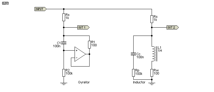
The gyrator is configured for an inductance of 1H, and R1 is the exact equivalent of the winding resistance of the inductor (Rw). The inductor's (exceptionally low) core loss is simulated by the 100k resistor and 100nF cap in parallel with the inductor. These also exist in the gyrator as C1 and R2. Provided the input voltage is maintained at no more than the maximum output swing of the opamp and well below the core saturation limits for the inductor, the two circuits perform identically. In each circuit, inductance is 1 Henry, Rs is the source resistance, and as shown the measured -3dB frequency for both high-pass filters is 169 Hz ...
f = Rs / ( 2π × L )
f = 1k / 6.283 = 159 Hz
The reason the formula and measured results are different is that the formula assumes the inductor is 'ideal' having no parasitic resistance or capacitance. Ideal inductors don't exist, so there will always be a small error when making calculations where inductors are involved. Gyrators are no different in this respect.
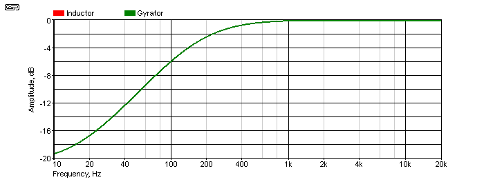
In the above, there are actually two traces, red for the inductor and green for the gyrator. They are so perfectly overlaid that you can only see the green trace, because the red trace is directly behind it and can't be seen. This response graph was included to show that the gyrator really is directly equivalent to an inductor. If there were a difference, it would be visible. The next step is to examine the phase shift, measured with an input signal of 100Hz. This is a sure-fire way to prove that the gyrator really is an inductor.
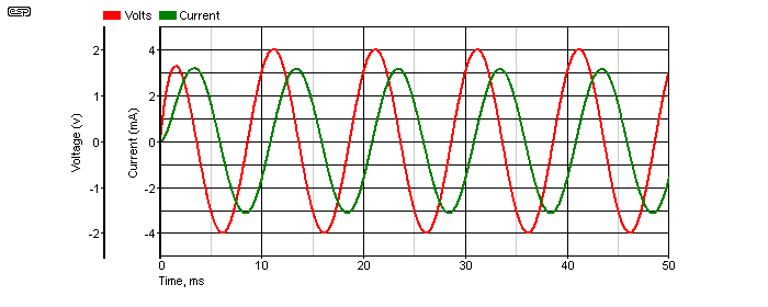
When we look at the voltage and current of the signal into the inductor/ gyrator we get the traces shown above. In an inductor, the current lags the voltage, and in Figure 3.3 you can see that this does indeed hold true for a gyrator - the same one as shown in Figure 3.1. If the circuit appeared to be resistive, voltage and current will be in phase. For a capacitor, the current leads the voltage - it may seem impossible for the current to come before the voltage, but it does (one of the many exciting things to learn about AC circuits in general).
In reality, it's often quite difficult to get an inductor to work as well as a gyrator. A small amount of DC won't affect the gyrator at all, but can have a dramatic effect on the inductor, especially at low frequencies where the core is likely to saturate. For example, it's very easy to have a gyrator with an inductance of 100H or more, but a wound component of the same value will be large, expensive, very susceptible to external magnetic fields and easy to saturate at low frequencies or with even small amounts of DC. Gyrator inductors can have extremely high inductance, yet will not saturate at any frequency as long as the current and voltage always remain within the limits of the opamp used.
That's not to say that gyrators are perfect by any means. They are built with real-world parts, and while resistors are usually very good (having very low stray inductance and/or capacitance), opamps have real limitations. So do capacitors, and depending on the intended use of the gyrator the caps you use can have a profound effect. The table in the previous section shows the basic characteristics of different dielectrics. For most applications you can use standard polyester caps, but (for example) a 1,000H inductor for a measurement system may demand a cap with lower losses and higher Q.
As noted earlier, a gyrator can easily be made adjustable, something that requires ingenuity and a friendly relationship with a machine shop to make the complex precision linkages you'll need to make a standard inductor variable. With a gyrator, all you need is a pot (potentiometer) and you can easily vary the inductance over a 10:1 range or more. This makes specialised tunable filters quite easy, and provides many useful options. The inductance presented by the gyrator shown in Figure 3.1 is calculated by ...
L = ( R2 - R1) × R1 × C1 (This is almost always abbreviated to the following, because the effect of R1 is usually very small.)
L ≈ R2 × R1 × C1
L ≈ 100k × 100 × 100n = 1 Henry
The usual way to make the gyrator variable is to vary R2. If it's increased to 200k the inductance will be 2H, and if reduced to 50k it will be 500mH. To obtain a different frequency range, C1 is changed. So with the values shown but making C1 200nF the inductance is again increased to 2H and with 50nF it's 500mH. This relationship works over a wide range, but there will always be upper and lower limits for R2 and C1 - neither should be made so large or so small that the values become unwieldy, or stray capacitance and resistance affect the results.
In general, C1 should be in the range of 10nF up to 1 or 2µF (otherwise the cap will be physically too large), and R2 will be in the range from 10k up to 1Meg or so. R1 should normally not be less than 100Ω as shown. Higher values will increase the inductance, but at the expense of additional series resistance that may have adverse effects on the filter circuit. In some cases the added resistance may be an advantage, so select the value as needed. Also, R2 is effectively in parallel with the inductor, and low values reduce the available Q, and this has consequences in filter circuits (especially when R2 is made variable as shown later in this article).
One of the most common applications for LC filters (whether made using 'real' or simulated inductors) is the resonant filter. This can be configured to be either a notch (aka band stop) or bandpass filter. Both are shown below. As before, the inductance is 1H. A notch filter is configured as a series resonant circuit, and the resonant circuit has a very low impedance at resonance. A parallel resonant circuit has a high impedance at resonance.
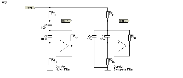
The signal is fed to each resonant circuit via the resistor 'Rs' (series resistor), and the resonant circuits are completed by either a series (Cs) or parallel (Cp) capacitor. Determining the resonant frequency is done just as one would calculate the resonant frequency of a traditional LC filter ...
f = 1 / ( 2π × √( L × C ))
f = 1 / ( 2π × √( 1 × 100n )) = 503 Hz
A series resonant circuit is effectively a short circuit at resonance, but that is limited by the winding resistance (R1 in the gyrator). Since that is a requirement for both real and simulated inductors, for these examples the total impedance cannot be less than 100Ω. A parallel resonant circuit is close to being open circuit at resonance, and again this is limited in real and simulated inductors by the effective parallel resistance (core loss) or R2.

At resonance, the impedance of the inductance and capacitance are equal. For the above example, resonance is 503Hz for both circuits. It's easy to determine the reactance of the capacitor and inductor using the traditional formulae ...
XL = 2π × L × f
XL = 2π × 1 × 503 = 3.16 kΩ
XC = 1 / ( 2π × C × f )
XC = 1 / ( 2π × 100n × 503 ) = 3.16 kΩ
In the case of series resonance, the two impedances are equal and the signal has opposite phase through each, so they cancel leaving only the stray impedances (winding resistance and capacitor ESR - equivalent series resistance). The result in the example shown is that the impedance across the series LC network is a little over 100Ω. For parallel resonance, the two impedances also have opposite phase, but now they cancel in such a way as to appear to be an open circuit. Again, this is limited by the inductor's parallel resistance (representing core loss) and by any leakage through the capacitor.
Because of the inevitable losses, the series circuit can't achieve an infinite notch depth, and the parallel circuit cannot achieve 0dB insertion loss at resonance. The notch depth is limited to -34dB (not infinite), and the maximum for the bandpass filter is -1.58dB (not zero). We can calculate that for the series circuit, the total resistance of the series tuned circuit is about 204Ω, and for the parallel tuned circuit it's around 50k. You want proof of that?
VD = ( R1 + R2 ) / R2
VD = ( 10k + 204 ) / 204 = 50 dB = 20 × log( 50 ) = 34dB
I leave it to the reader to do the same calculation for the parallel tuned circuit (and yes, it gives the result I measured  ). While you don't need to remember all of this, you do need to be aware of the limitations. That way, you won't be quite so puzzled when you see some of the effects of using gyrators (or even inductors) in real circuits. This really starts to show up when you use tunable filters based on gyrators, and you'll see the Q and peak amplitude change as the gyrator's inductance is varied. This is because the Q of the circuit is changed because of the effective parallel resistance, represented by R2.
Determining the Q is (supposedly) simple, but the formulae provided in most texts are often wildly inaccurate. Q is measured by taking the centre frequency (503Hz in the example above). Then the -3dB frequency above and below resonance are determined, providing the bandwidth. With the Figure 4.1 circuit, the bandpass bandwidth is 192Hz, and Q is simply ...
Q = fo / BW
Q = 503 / 192 = 2.62
When used as a series resonant circuit, the Q is completely different! The same formula is used, but the notch filter has a much higher Q. The bandwidth of the notch is 31.8Hz, so Q is 15.8. The determination of Q is always an approximation, and while a calculated value is usually accurate enough, if you need to know the exact value it can only be done by measurement (either on the workbench or using a simulator).
An 'active inductor' is basically a gyrator by another name. However, there are some differences in both the circuit itself and the way it works. Most common active inductors use two equal value resistors, typically 1k. The schematic below shows the difference between a gyrator and an active inductor, both set to provide the same inductance - 1 Henry. As with a 'standard' gyrator, inductance is calculated as R1 × R2 × C1. The 'equal resistance active inductor' generally has worse performance than a gyrator and usually needs a much larger capacitor, but may be useful in some cases - especially where small values of inductance are needed.

The circuit shown for the active inductor is fairly typical, and R1, R2 are usually equal. One issue is that the capacitor is a much higher value, and the opamp load is increased. The opamp may be expected to provide as much as 10 times the output current for an active inductor compared to a gyrator. As resistor values are reduced (to obtain a lower 'winding' resistance), the cap must be larger and opamp current increases until a point is reached where the opamp cannot provide enough current. The circuit will then distort. Opamp output current is highest at high frequencies - well above the cutoff frequency.
For example with the two circuits shown above, input was 1V peak (707mV RMS) at a frequency of 1kHz. The gyrator opamp output current is 405µA peak (288µA RMS), and the opamp in the active inductor circuit will have to provide 2.46mA peak (1.74mA RMS). At 10kHz the current in the gyrator's opamp output is 48µA RMS, and that from the active inductor increases to 3.4mA RMS. At high frequencies the opamp is least capable of providing significant output current, so the active inductor is at a great disadvantage. As the frequency is increased further, gyrator output current falls, but output current for the active inductor remains high. Low frequency output current favours the active inductor, but there's no significant advantage. The frequency response is shown below.

You can see that the active inductor can only reduce the level to -20dB at low frequencies, and this is due to the extra resistance (R1 = R2 = 1k). You will see that the frequency is higher than the previous example shown in Figure 3.1, and that's because the series resistors are 10k, not 1k as before. With a 1k resistor, the active inductor can only reduce the level by 6dB. This is not always a disadvantage though, as you might only need 6dB, depending on your specific requirements.
In general, the active inductor offers no real benefits, but needs a larger cap for the same inductance and places higher demands on the opamp at frequencies above cutoff.
To make a gyrator variable, all that's needed is to use a pot instead of one of the resistors. Making R2 variable would be a bad idea, as that will change the effective series resistance and change operating characteristics. In the drawing below, you can see that R1 has been replaced by a pot with a resistor in series. A fairly sensible arrangement might be to use a 22k resistor and a 100k pot. For the circuit shown using 100k for both the resistor and pot, that means the inductance can be varied from 1H to 2H - a ratio of 2:1. The range can be increased, but that comes with some caveats.
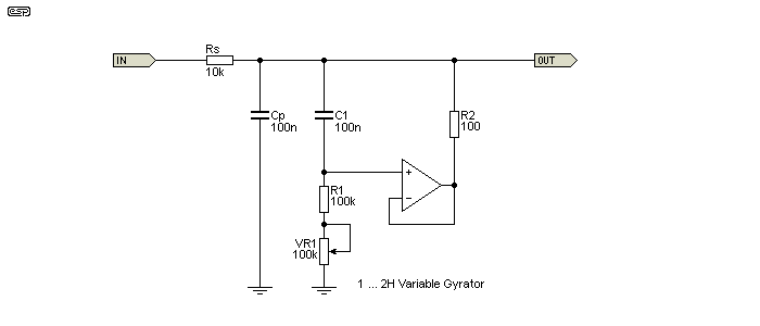
The above schematic shows a parallel tuned circuit. The inductive leg of the tuned circuit is a variable gyrator, and inductance is changed by using VR1. The pot can be a higher resistance to get wider range, but the circuit's overall Q will change quite dramatically as a result. This is why most variable gyrators are limited to a fairly low ratio if a reasonably consistent Q is needed.

You can see in the response diagram that the Figure 6.1 circuit changes the resonant frequency from 356Hz (pot at maximum resistance) to 503Hz (pot at zero). By repositioning the parallel cap to a series tuned resonant (as shown in Figure 4.1), you have a notch filter that can be tuned over the same range. You can also change the range by changing the value of C1 or Cp (Cs for a series tuned network). As you can see, the Q and insertion loss changes as the inductance is changed, and this needs to be looked at to see why.
In reality, neither insertion loss or Q is easy, and they are the result of complex interactions. The impedance on the capacitive and inductive parts of the circuit is 3.16k when the gyrator is configured for 1H inductance, and the Q is 2.6 for the LC network. At 2H, the impedance of both branches (capacitive and inductive) is 4.7k, so the Q is reduced to 2.05 - it's not as great because the impedances in each branch are closer to the value of the feed resistor (Rs).
For the highest Q, the impedance of the inductive and capacitive branches has to be as low as possible - lower impedance means higher Q. This means that the inductance must be reduced and the capacitance increased. There are limits though, and it's unrealistic to expect very high Q from gyrator based filters. Trying to increase the Q beyond reasonable limits will cause much greater insertion loss. The approximate Q for a parallel tuned circuit can be determined by ...
Q ≈ Rs / ( XL + R2 ) Where Rs is the series resistance, XL is inductive reactance, and R2 is the feedback resistor in Fig. 8
Q ≈ 10k / ( 3.16k + R2 ) ≈ 3.07
Another factor that causes the Q to change is the gyrator's parallel resistance (R1 and VR1 in series). Adding the parallel resistance reduces the Q just as it will with a 'real' inductor, because it adds damping to the circuit. With physical inductors you still have the same effect, due mainly to core losses (assuming ferrite or laminated cores). These don't exist in air-cored inductors of course, but due to the low values of inductance available, they are limited to radio frequencies. As noted already, the Q is very different for two filters using the same values, but configured as series resonant or parallel resonant circuits. With series resonance, the impedance is at a minimum, and Q is determined by the series feed resistance.
Fortunately, it's very rare that high Q filters are ever needed, and if you do need a very high Q bandpass or band stop (notch) filter then there are much better alternatives, such as the multiple feedback bandpass or twin-tee notch filters, or one of the 2-opamp variations described in Section 13 of this article. If you need to be able to tune the filter as well, then you can use a state-variable type, probably the most versatile filter topology ever created. The cost (of course) is complexity.
Sometimes, you might need a number of filters, and the cost of opamps may be prohibitive, both in monetary terms as well as PCB real estate. In these cases, you might consider using an emitter follower rather than an opamp. There are caveats of course, but whether they cause a problem depends on the application. In some cases, you may find that you need more parts with an emitter follower gyrator, but they will make the PCB layout much easier.
Gyrators can also be made using JFETs or even valves (vacuum tubes), but the performance of both is worse than a transistor. Even a transistor isn't wonderful, but it is usable if you don't need optimum performance. JFETs and valves are even worse, and in general should be avoided.
It must be understood that there is a fairly large difference in performance if you use anything other than an opamp. If you happen to be designing a piece of test equipment then the loss of performance will probably be unacceptable, but for an audio equaliser it may be quite alright. By way of comparison, look at the circuits below.
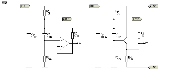
The transistor version only needs one extra resistor, but it also needs quiet power supplies because there is almost no power supply noise rejection. The output will also be pulled to a voltage somewhat less than zero, and in this case it will be around -2.3V, but it depends on the gain of the transistor and the value of R1. The DC offset may or may not be a problem, depending on the application. Because the transistor's drive capability is not as good as the opamp, R2 has been increased to 560Ω, and C1 reduced to 18nF. This still provides roughly 1H, but it will be a little less with the transistor because of its gain (only about 0.998 instead of unity). That small loss of gain makes a measurable difference!
There's a little trick that you can use too, but it only works with a parallel tuned circuit as shown here. The output can be taken from points 'A' or 'B' instead of the normal output terminal, and the performance is improved by doing so. The effect is greater with the opamp (as you'd expect), but it also improves the transistor version sufficiently to make it a much more useful circuit.
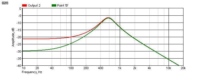
As you can see, the response when the output is taken from Point 'B' is better at the low frequency end of the spectrum. There's 5dB improvement at 100Hz, and it's about 8dB better at 20Hz. That's a worthwhile increase in rejection of 'out of band' signals, simply by changing the location of the output terminal. The improvement is even more dramatic with the opamp version. The high frequency end of the spectrum isn't affected, because that part of the filter is provided by the capacitor which has no significant limitations due to series resistance.
This is where things get 'interesting'. The standard circuit topologies, including the simple emitter follower, but converted to cathode/ source follower, don't work. The 'work-around' leads to an end result that's quite a clever bandpass filter, but it's not a gyrator. For starters, the circuits are configured to have gain, and this isn't the case with a 'true' gyrator. There also doesn't appear to be a sensible way to determine the frequency. Both are shown tuned to 1kHz, but this was done by simulation, not calculation. The valve circuit is based on a simulation of the first 'graphic' equaliser - the Blonder-Tongue 'Audio Baton' (ca 1956) [ 11 ], and the JFET version is simply a 'transformation' of the valve design, with impedances changed to suit the low voltage supplies. A JFET wired the same way as a bipolar transistor works, but not very well (in fact, the performance is best described as woeful). It can be improved, but only with additional complexity.
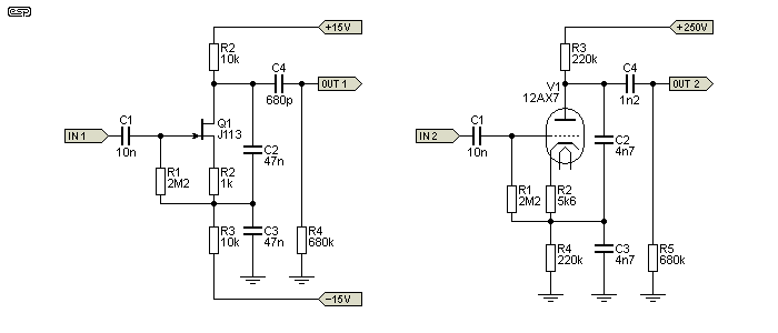
With both circuits, almost everything affects the tuning frequency. The source/ cathode and drain/ anode resistors both have an effect, and the output coupling cap (C4) is necessary to roll off the low frequency component. If this is too large, the output will fall by 10dB (JFET) or 20dB (valve) and flattens out - the response does not continue to fall. With the values shown, both have a peak frequency of (close enough to) 1kHz. The JFET version has a gain of 9dB, and the valve version has a gain of 17dB. The Q of each is a little different - 1.0 (JFET) and 1.45 (valve).
I don't propose to cover these in any further detail, as IMO they are marginal at best, difficult to tune properly, and far more complex than an opamp. Both the circuits are made more complex by the requirement for biasing, and it's largely that which means that they have a completely different topology from the 'true' gyrators shown throughout the rest of this article. While I'm sure that there is a formula that can be used to determine the component values for any given frequency, I don't intend to try to determine what it might be.
While not especially useful, the valve/ JFET version can also be adapted to use a BJT. It's easy to make it perform better than the valve (which should come as no surprise), but it's still a bandpass filter and not a gyrator. Compared to a multiple-feedback bandpass filter (opamp based) it doesn't come close. The MFB filter also provides the option to select the gain, Q and frequency independently, something that can't be done easily with the circuits shown in Figure 7.2.1.
It's worth knowing that the vast majority of 'valve gyrator' circuits you may see on the Net are nothing of the kind. Most use a current source as the anode load. While this improves linearity, it is not a gyrator by any stretch of the definition.
You may well ask why this isn't at the top of the article, but it's here for a good reason. Until you appreciate all the interesting things you can do with gyrators and see them in action, there's not much incentive to understand how they work. So, after describing what they can do, hopefully the reader will be interested enough to want to understand the finer points of how the gyrator manages to mimic an inductor. In most cases, the opamp is connected as a unity gain non-inverting buffer. Being able to 'create' an inductor is extremely useful, because it means that we can make resonant circuits very easily.
One explanation for how a gyrator functions is to look at the way the cap is connected. C1 and R1 in all the examples are wired as a differentiator. The circuit's input is then 'bootstrapped' via R2, which transfers the functionality of the differentiator to the circuit's output. In most of the examples shown in this article, inductance is set to 1H, with C1 being 100nF, R1 is 100k and R2 is 100Ω. We know that an inductor fed from an AC voltage source will appear to be a high pass filter, and we need to look at some drawings to understand this better.

Filter 'A' is a simple high pass filter using a capacitor - a differentiator. In many cases this is all we might need, but we may need a true reactive component that's the functional opposite of a capacitor. So, we start with the arrangement shown in 'B' and add a buffer and a resistor (R2) as shown in the previous examples. We want to end up with 'C' - an inductor. By monitoring the voltage across R1, buffering it and sending it back to the input via R2, we have created the functional equivalent of an inductor. The voltage across C1 in 'B' is shown, and it is only ever a small fraction of the input voltage because of the buffer and R2.
The opamp circuit reproduces the voltage across the resistor (R1) rather than that across the capacitor (C1). Therefore the circuit effectively inverts the impedance characteristics of the capacitor. The inverse of a capacitor is an inductor, and that's what is presented to any external circuit. None of this can be considered intuitive though, and it's not always an easy concept to grasp.
All the diagrams and waveforms in the world don't actually help you understand how a gyrator works. It will also require a small 'leap of faith' for the reader, as understanding exactly what happens is not intuitive. You also need to understand exactly what an inductor does when it is presented with a signal. An inductor presents a low impedance to low frequencies, and the impedance increases with increasing frequencies. An ideal inductor is effectively open circuit at the instant it is presented with an external DC voltage, and it takes time for the current to reach the maximum value.
Perhaps surprisingly, one of the easiest and best ways to describe how a gyrator works is to analyse what it does when presented with a DC voltage with a fast rise time. Ideally, it will behave like an inductor, and limit the risetime of the current. To understand all of this properly, you will need good analysis skills, and a simulator that includes ideal components will be very helpful. Otherwise, you can follow the text here and just accept the descriptions I provide. I recommend that you try it yourself though - experience is the best teacher.
An inductor opposes current flow, so at the first instant when the DC is applied, no current flows. Depending on the source impedance and the inductance (which determine the time it takes), the current gradually builds until it is interrupted or reaches its maximum possible value. Maximum current is determined by the applied voltage and the total circuit resistance. A gyrator should behave the same way, and with a good opamp (one approaching 'ideal') a gyrator will come very close. If we can get a gyrator to behave like an inductor then we have successfully demonstrated that they are equivalent.
Simulation of an inductor and a gyrator built with the simulator's 'ideal opamp' shows that the performance is identical in all respects. Of course, real (as opposed to ideal) opamps won't perform as well, and in particular they are incapable of producing the 'flyback' pulse that one gets from an inductor. This isn't a limitation of the gyrator itself, only the opamp, which has finite supply voltages that cannot be exceeded. If you were to build a fast unity gain buffer that could operate from ±100V supplies, then everything described here will really happen! Yes, it is possible to design such a circuit, but I'm not about to do so.
Assume a suitable inductor, fed from a 12V supply with a 1k limiting resistor (Rs). In the inductor, the rise of current is suppressed by the magnetic coupling. Lenz's law states that "An induced electromotive force (EMF) always gives rise to a current whose magnetic field opposes the original change in magnetic flux." In other words, the application of a voltage causes a current to flow that creates a magnetic field, which in turn generates a back EMF in the inductor that opposes the externally applied voltage. The instantaneous voltage at the inductor terminals is the full external voltage, and as current increases through the inductor the voltage will fall. After a period of time that depends on the inductance, the current through the inductor will be 12mA (12V / 1k) and the voltage across it will be zero.
The above assumes an ideal inductor, and we know they don't exist. As a result, the voltage can only fall to a final figure that depends on the external resistance (R1 - 1k) and the coil's resistance - let's say 100Ω (R1). The minimum voltage across the coil is therefore just under 1.1V ...
VD = ( Rs + R1 ) / R1 Where VD is the voltage division, Rs is the external resistance and R2 is the coil's resistance
VD = ( 1k + 100 ) / 100 = 11
Coil voltage = supply voltage / VD = 1.0909V
Now, let's see what the gyrator does, and an ideal opamp will be assumed for the time being, but using the same resistances as discussed above. When the input signal is applied, C1 is discharged. We know from my 'first rule of opamps' (see Designing With Opamps) that an opamp will try to make both inputs the same voltage. Since C1 is discharged, it acts like a short circuit (for an instant in time), so the opamp's output is the same as its non-inverting input, and the opamp and surrounding parts appear to be an open circuit. See the drawing below so that you can follow the logic. Initially we will ignore Rd (a damping resistor) - more about that soon. The gyrator inductor has a value of 10H. The 'ideal' opamp has no limitations on its supply or output voltage, and has infinite open loop gain and bandwidth. Unfortunately, it's a component restricted to (some) simulators, and it doesn't exist in real life.
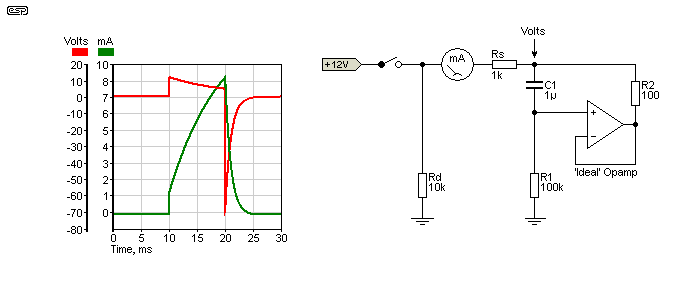
On the graph, the switch is closed at 10 milliseconds and the voltage across R1 will be close to the full 12V - it's actually 11.88V because Rs and R1 create a voltage divider via the capacitor (C1). As time passes the capacitor charges via R1. As it does so, the voltage at the non-inverting input starts to fall, and so too does the opamp's output to ensure that both inputs are the same voltage (my first rule of opamps). Meanwhile, the current rises as shown in the green trace. After a period of time set by Rs (source resistance), R1 and C1, the voltage at the non-inverting input will be back to zero (or close to it), and so will the output. Current flow is therefore from the external DC source, through Rs, through R2, and finally flows into the opamp's output (opamps can supply (source) and sink current). R2 is equivalent to the coil's winding resistance, so is in series with Rs and limits the maximum current to 10.09mA.
Things get really interesting when the switch is opened, and it is this behaviour that absolutely proves that an ideal gyrator is exactly equivalent to an inductor! The switch is opened at 20ms, and the current has reached 7.23mA (we are still ignoring the current in Rd). C1 is partially charged, and when the switch opens there is no longer any input current. The opamp's inputs are momentarily at different voltages. Since the opamp will always try to make both inputs the same voltage, the only way that can happen is for the output to swing negative by over 70V. Rd (the damping resistor) is now in effect, as things tend to get silly without it.
At the time the switch is opened, C1 is charged to 723mV, which means that there is also 723mV across R2. The current in R2 is therefore 7.23mA. The opamp must now try to send 7.23mA back through R2, then Rs and Rd (these last two being effectively in parallel with R1), a total of 9.09k. A quick application of Ohm's law tells us that the gyrator's output voltage must now be -71.64V (7.23mA through 9.09k). If Rd is not present, the voltage will attempt to reach 723V because there is nowhere for the opamp's output current to go except to discharge C1 via R1 (7.23mA and 100k = 723V), and that would be silly. 
Unfortunately, ideal opamps don't exist, so the peak negative voltage will be clamped to the opamp's negative supply rail (typically -15V). It will still try to do the same as the ideal opamp, but it's a real component with real limitations. It should now be obvious that an ideal gyrator can mimic every aspect of an inductor. As long as the input is within the capabilities of a real-world opamp, the behaviour when DC is applied to the input is still the same as a real inductor - only the flyback pulse can't be duplicated if it tries to exceed the supply voltage.
So as you can see, if the ideal opamp gyrator mirrors an equivalent inductor perfectly with a DC input, it follows that it will also mimic an inductor with AC inputs, as demonstrated in all the example circuits above. Once we establish and understand the limitations of a real opamp, it's obvious that the gyrator will behave like an inductor in all respects. As is also obvious, this only happens if the applied signal does not push the opamp outside its limits (slew rate, output current and supply voltages).
The transistor version has limitations from the outset, but it will still attempt to mimic an inductor to the best of its abilities. With audio frequency signals, it doesn't do a bad job for such a simple circuit.
Project 28 is a quasi-parametric equaliser, and shows a fairly adventurous use of tunable gyrators. It uses all the tricks that have been described here, plus a few more. It uses 3 gyrators to cover the range from 35-150Hz, 120-550Hz and 500-2,200Hz, offering either shelving or peaking for the lowest frequency range.

Above is the bass section of the equaliser. When the switch is closed (shorting out C2), the equaliser acts in 'shelving' mode, the same as a normal tone control, but with variable frequency. When the switch is open, C2 and the gyrator operate as a series tuned circuit, providing a 'peaking' response, and allows a peak or notch that can be tuned. The frequency range (peaking mode) as shown is from 30Hz to 140Hz. The graph below is very busy - lots of different traces - but it gives you an idea of what can be achieved. You can also see that the last 25% of the pot's travel covers a wide frequency range, and it is difficult to get a nice linear response from the frequency pot.
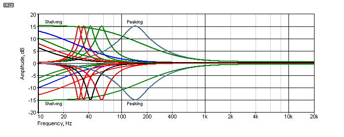
Each trace on the graph is with the Boost-Cut control at 0% and 100% (maximum cut and boost), and the frequencies are shown with settings of 0%, 25%, 50%, 75% and 100% on the frequency pot. With the Cut-Boost pot centred, the response is flat. This is an extremely flexible circuit, but it wins no prizes for consistent Q (which varies with all L-C variable tuned circuits (state-variable filters can maintain constant Q). However, it is very usable - I have a full version of Project 28 in my workshop as part of my audio test and monitoring system.
Any or all of the frequency determining parts can be changed to give different results. VR1 is normally duplicated for as many EQ channels as desired, and a great many graphic equalisers (even down to 1/3 octave) were built using gyrators as part of the tuning circuit. Before gyrators, ferrite pot-core inductors were often used - a vastly more expensive option, especially since there could be up to 31 of them for a mono 1/3 octave graphic.
The ability to tune gyrators over a fairly wide range makes them far more suitable than coils for tone controls and other forms of equalisation. Although the opamps used will always contribute some noise, they will usually be quiet enough for the vast majority of applications. Compared to the cost, complexity and PCB real estate required by alternatives such as state variable filters, gyrator based filters can be almost as flexible, but lack the ability to change frequency without affecting Q. In reality, this is not usually a problem for filters used as 'tone controls' used to modify the response to suit the listener. Correcting for room and/ or loudspeaker anomalies only applies within limits - speaker correction is easy enough, but 'room EQ' is largely a myth. Room effects are caused by time delays, and you cannot correct time with amplitude!
A gyrator in its simplest form used to be a common line termination for so-called POTS (plain old telephone system/ service) analogue phones. It is a requirement of any phone that it should be able to pass the DC from the phone line, but present a specified impedance back to the exchange (aka 'central office'). During line testing and other activities, it is necessary to use a circuit that will draw the required current from the phone line, but not interfere with the termination impedance. In most modern phones, the gyrator forms part of the IC that controls the telephone, and is not a separate entity.
Early telephones used an inductor (or more correctly a 'hybrid coil', which is a tapped inductor). As phones became electronic the inductor was a needless expense, because they have to be quite large and expensive in order to handle the DC through them. A standard phone line from the exchange can deliver in the order of 50mA to a shorted line, or around 20-25mA in normal use at the end of the cable from the exchange to a house. The telephone itself should have about 5-10V DC across it when in use.
At one stage of my life I designed specialised telecommunications equipment, and particularly equipment that used standard phone lines. In order to be able to test (and take detailed measurements), I built a number of phone line termination units which mimicked a telephone, but did not have any microphones or ear-pieces. These (and the terminations in some telephone systems) used the simplest form of gyrator possible.
Essentially, the circuit is just a high gain transistor with its input bypassed with a capacitor. It can only react to DC and appears to be an open circuit to AC (in this case the speech signal). Does this qualify as a gyrator? Perhaps not, but it is a simulated inductor, and behaves like a real inductor. It passes DC unhindered but in a controlled manner, but is virtually open circuit to AC above 100Hz or so. You might well ask "why not just use a resistor?" You can, but it will present the wrong impedance for AC back to the exchange, and that can cause echoes and other interference on the speech circuit. A resistor also cannot compensate for different line resistance. If we assume that the full 50mA is available from the exchange then a 200Ω resistor will work, but that is completely wrong for the speech circuit and will be far too low if there is significant line resistance.
By using a specially designed gyrator, the line will appear to have the right resistance for the DC provided through the phone line, but will not affect the AC impedance so that can be handled properly by the hybrid (if you really want to know, see 2-4 Wire Converters / Hybrids). The circuit below will draw about 38mA from a 1,000Ω feed system (zero length phone line), and about 20mA if there's an additional 1,000Ω of line resistance. The terms 'Tip' and 'Ring' come from standard phone plugs, which were designed for and used in early manual telephone exchanges.
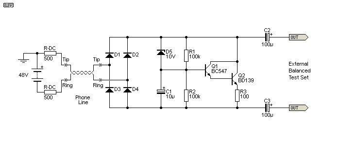
The impedance of the circuit is over 40k at all frequencies above 100Hz, and is over 50k for all frequencies above the phone system lower limit of 300Hz. The zener diode ensures that the maximum current is drawn immediately, and if it's not there the circuit will fail to seize the phone line fast enough for the exchange equipment to recognise it. During normal use (about 20ms after the circuit connects to the phone line), the zener does not conduct. The effective DC resistance to the phone line is about 280Ω with a 48V supply via a 1kΩ DC feed network.
In all respects, the behaviour of the circuit is the same as a high value inductor. It has a low resistance to DC, yet has high impedance for AC, exactly the conditions we expect from an inductive circuit. It is a very simple gyrator, but it satisfies the criteria to qualify. Attempting to use it as part of a tuned circuit is not recommended because it won't work. Not because it doesn't appear inductive, but because the simulated inductance is dependent on the gain of the transistor pair and is therefore unpredictable. This doesn't affect its operation as a telephone line DC terminator.
Note that all phone systems have a designated impedance that applies to audio signals, and that is not shown in the above drawing. The impedance is used at both ends of the phone line so both ends of the line are properly matched. Further discussion of this is outside the scope of this article. However, it's still worth noting a few points about the circuit shown. The diode bridge at the input is required because telephone equipment should not be polarity sensitive, and must be able to function if +ve and -ve are reversed.
R1 and R2 deliver a very small current to the base of Q1, which in turn drives Q2, and draws current from the line. AC (signal) to the base is removed above a few Hertz by C1, preventing the transistors from affecting the signal, only the DC. Finally, C2 and C3 are used to connect to external test equipment with floating (not earthed) balanced inputs. Telephone systems are always balanced, because they use long, unshielded twisted pairs that would otherwise pick up a lot of noise.
There are two other types of gyrator that are classified as a 'GIC' (generalised impedance converter) and FDNR ('frequency dependent negative resistance', or 'functionally dependent negative resistance'). These are usually quite specialised and are unlikely to be found in many circuits that hobbyists will come across. Some are so specialised that they are intended for inclusion in CMOS integrated circuits and aren't normally found as discrete circuits.
Potentially of some interest is the negative impedance converter, and that can be built using one or more opamps. I don't know where anyone would use one, but the concept is quite fascinating. It is usually easy enough to simulate some of these circuits using 'ideal' opamps, but realisation with real opamps is often problematical to the extent that the circuits simply won't work properly (if at all).
Some of these circuits can be classified as theoretical, in that they might be coaxed into functioning in theory or even perhaps in a simulator, but should you build one it will refuse to work. Others (such as the one shown below) do work, and this particular circuit works extremely well - so well that it simulates an ideal inductor, with zero winding resistance. Of course, and in deference to the 'no free lunch' principles that define physics, this comes at a cost.
Firstly, it is far more complex than those we've looked at before, and its dynamic range can be severely limited if the source impedance is too low. As shown, the maximum gain is at low frequencies, and both opamps have to operate with an internal gain of 26dB (x 20) when driven from a 1k source impedance. Increasing the source impedance to 10k means that U1 and U2 operate with a gain of 2, but the dynamic range is still more limited than you can get with a simple gyrator as described earlier. The interesting part of the circuit is based around U2, which is a negative impedance converter (NIC).

The NIC (negative impedance converter) effectively removes the simulated 'winding resistance' that affected the simpler gyrators, but at the cost of high internal gain and limited input level before distortion. In normal uses, this is probably not a serious limitation, but you do need to be aware that it happens if you wish to experiment. If any opamp clips, then circuit behaviour cannot be measured with any accuracy because the opamp is outside of its linear range.
The inductance of the circuit is determined by the resistors coloured yellow. The others (R4, 5, 6 & 7) only need to be all of the same value (such as 10k, or perhaps 22k), and changing them does not affect the inductance. The only reason I used a different value for these was to make it obvious that they are not part of the inductance calculation. You can experiment with differing values for R4 - R7, but the results will probably not be useful. With the values shown inductance is 1 Henry, and is determined by ...
R = R1 = R2 = R3
L = R² × C1
As you can see from the circuit and inductance formula, very high inductance can be achieved with small capacitors and relatively low value resistors. To get a 10H inductor, you can use a 100nF cap and 10k resistors. If resistor values (R1, R2 & R3) are increased, so is the gain required by the opamps for a given source impedance (Rs). You can reduce the resistance and use a bigger capacitor, but then the opamps (in particular U2) may have difficulty providing enough current. There are many interactions in this circuit, and it's not sensible to try to explain them all in a short article.
I haven't shown the response graph simply because it's very similar to those shown earlier, except that the equivalent inductor has zero 'winding resistance'. So, where those described earlier had the equivalent of 100Ω or 560Ω, this one has none at all. This changes the response at the extreme low end, because the Figure 11.1 circuit can provide zero resistance at DC. While this might seem to be very useful, in most cases there is no real benefit.
If the capacitor in Figure 11.1 is replaced by a voltage source (AC or DC), the output will provide a constant current into any load that's within the limits of the opamps. While it is an excellent current source, it's also far more complex than necessary and has a very limited application. However, the fact that it can be used this way is one of the reasons that this class of circuit is referred to as a 'generalised impedance converter' (GIC). It simply converts impedances from one type to another, and/or inverts the reactance type, making a capacitor behave like an inductor and vice versa. In the case of a voltage source in place of C1, it converts a voltage to a current or can convert a current into a voltage (a single resistor works much better for the latter task though). All of this falls into the category of 'fascinating but not very useful'.
I do not intend to cover some of the more esoteric gyrator designs because it is extremely unlikely that you will ever come across them. Some are quite interesting, but simple explanations are not possible because of the circuit complexity and interactions. Even the one shown in Figure 11.1 is far more complex that you are ever likely to need, although it does perform well. It's better in some ways, worse in others compared to the simple circuits described earlier. However, there are no applications that I can think of that actually require the use of an 'ideal' inductor.
I know I said that I wasn't going to talk about frequency dependent negative resistance (FDNR) circuits, but a simple example is certainly worth including so you recognise it if ever you come across one. The circuit shown below was adapted from a paper that seems to be very common the Net, and the exact same circuit appears to be repeated in several different papers by different people [ 10 ]. It's normally shown as a three stage filter, but I have reduced it to a single stage for simplicity. The frequency can be changed simply by varying R4 and leaving all other values the same.

Although the circuit doesn't look overly complicated, I have no intention of even trying to explain the maths behind how it is designed. This is a complex circuit, with very convoluted interactions between the two opamps that are impossible to analyse in simple terms. As you can see from the near equivalent circuit using inductors, a single FDNR stage manages to emulate two floating inductors and a capacitor. The two circuits shown are only approximately equivalent, because I used standard values rather than the decidedly non-standard values that would normally be required - especially for the LC filter. The approximation is mine - if you follow through the maths behind the FDNR you will discover that exact copies of L/C filters can be created.
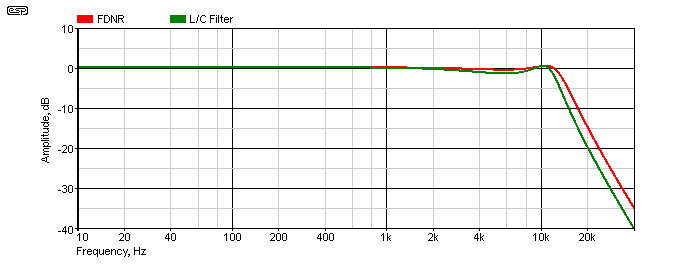
The response of the two filters is shown above. As noted, they are not identical because I used standard value parts, but when implemented according to the rather daunting maths formulae and using high precision (very non-standard) parts for the two, they will be exactly equivalent. The filter response for both shows Chebyshev behaviour, with some ripple in the pass band just before rolloff. Changing R4 from 560Ω to 470Ω makes the -3dB frequency the same for both, but I left it as is so you can see the separate traces.
The FDNR opamps will operate with some gain (especially U1), and as always this may cause the opamp to overload and ruin the filter characteristics. Input signal levels must be kept low enough to ensure that there is never any distortion, as this indicates opamp overload. Both circuits provide a rolloff of about 20dB/octave when measured between 20kHz and 40kHz (the -3dB frequency is approximately 13kHz). While the circuit is impressive and a potential source of wonder, the same results can be obtained from much more conventional active filter circuits, that are easier to design, build and troubleshoot.
There are a couple of other 'GIC' (generalised impedance converter) circuits shown in Section 13. The FNDR is a 'specialised' case of a GIC, and both can use similar circuit arrangements.
The following circuits are variable capacitors, and these are not technically gyrators, although they do follow the same basic form. They are capacitance multipliers, and can be used in place of a fixed capacitor to obtain variable frequency tuning. As shown in Figure 12.1, capacitance is variable between 11nF and 110nF, although it can have much greater range if desired. For audio (such as equalisers and the like), the range shown will be more than enough.
Note: A word of warning is required for the single opamp circuit. Under some conditions (which, believe it or not can be intermittent), the circuit may decide to 'latch-up' to nearly the full voltage of one polarity or the other. Although I've used them a number of times with no issues, the latest attempt (part of a stereo equaliser circuit) suffered from this problem. Mostly, they behaved themselves, but every so often one or both channels would latch to a supply rail. Turning off and back on again almost always fixes the problem, but I've never been able to see it happen on the workbench. It seems that the circuit knows when test equipment is nearby, and refuses to misbehave.  The reason so far remains a mystery, but note that the circuit does have positive feedback that's DC coupled!
C2 is a recent addition, and it removes the DC feedback component and should prevent latch-up. The polarity is unimportant, as there's very little voltage across C2. Operation is otherwise unchanged. Please note that I've not been able to absolutely verify that this will work, because I've never been able to get the circuit to latch-up on the workbench.
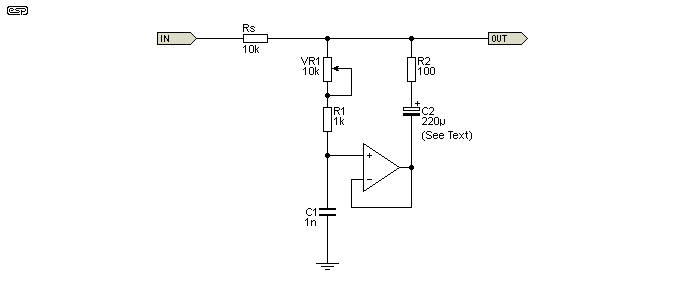
The only difference between this circuit and a gyrator is that the positions of the cap and a resistor have been reversed. Go back and have a look at one of the other circuits so you can see this for yourself. Capacitance is determined by C1, R1 + VR1 and R2 and the formula is ...
C = C1 × (( R1 + VR1 ) / R2 + 1 ) Assume VR1 is at maximum resistance ...
C = 1n × (( 1k + 10k ) / 100 + 1 ) = 111nF or ...
C = 1n × ( 1k / 100 + 1 ) = 11nF VR1 at minimum resistance
I won't bother showing the response, because it's just a first order low pass filter and rolls off at 6dB/octave after cutoff. The only difference between this and any other capacitor is that this one can be used to create a variable cap that is far greater in value than anything you might be able to buy. Like the gyrators from which the circuit is based, it has some series resistance and that limits the ultimate attenuation. For example, with the values shown, the ultimate attenuation at high frequencies is about 40dB, due to the 100Ω resistor.
In case you were wondering, no, you can't use it as part of a DC filter in a power supply. The current is limited by the opamp, and the voltage is limited to the opamp supply rails. If you need to reduce ripple from a power supply, see Project 15. This capacitance multiplier is intended for equalisation circuits or other places where you might be able to use a somewhat less than perfect, high value variable capacitor (that isn't the size of a small car).
There's another version of a capacitance multiplier that uses two opamps, and although it has some advantages over the one shown here, it has some serious limitations as well. Much like the two opamp gyrator, it can require high opamp gain and may unexpectedly overload (distort) as a result. The circuit diagram is shown below.
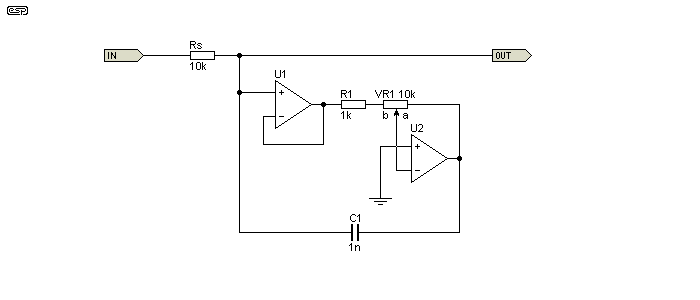
The gain of U2 is variable from zero (VR1 wiper at position 'a') up to a maximum of 10 (wiper at position 'b'). With the values shown, the maximum gain is 10, so U2 may distort prematurely if the input voltage to U1's non-inverting input is greater than around 500mV at any frequency. Capacitance is determined by ...
C = C1 × ( G + 1 ) where G is gain set by VR1 ... C = 1nF × ( 0 + 1 ) = 1nF with VR1 at position 'a', and ... C = 1nF × ( 10 + 1 ) = 11nF with VR1 at position 'b'
Unlike the two opamp gyrator (shown next), the two opamp capacitance multiplier has no series resistance so is theoretically 'lossless'. However, the internal circuit gain can be such that opamp distortion causes signal distortion, but it may not be immediately apparent and the cause may seem somewhat mysterious. Given that issue and the fact that it needs two opamps instead of one, the Figure 12.1 circuit is preferred, even though it requires an extra resistor (a small price to pay).
Either of these circuits could be used in the same circuit arrangement as shown in Figure 9.1, providing a variable frequency shelving treble tone control. They can also be used as part of a parallel tuned circuit, with the inductive element provided by a gyrator. Because the circuit is earth (ground) referenced, it cannot be used as part of a serial tuned circuit, and in that respect it has the same limitations as a standard gyrator.
Another topology needs to be looked at, because it isolates the parallel resistor and improves the Q of the gyrator. By adding a buffer opamp, the 'damping' resistor to ground is 'isolated' from the input, and it no longer affects a parallel or series tuned circuit. However, this does not change the reality by as much as you'd imagine, due to the very nature of tuned circuits. Nor does it eliminate the series resistance - as with real inductors, the 'winding resistance' cannot be eliminated with this circuit. Unlike the conventional gyrator, this circuit cannot be used to obtain a series resonant (notch) filter. It only works in parallel resonance mode.
The overall Q is determined by the feed resistance, and if the inductor (gyrator) and capacitor aren't both changed, the circuit's Q changes. The two-opamp gyrator isolates the parallel (damping) resistance, and this can be useful if a high Q circuit is needed. The alternative output ('Out2') may be useful if there's a need to drive low impedance circuits. It doesn't affect insertion loss (see below), but it does provide better rejection of very low frequencies because R2 can't cause the response to level out as frequency falls (that's not usually a problem, but the low output impedance is useful).
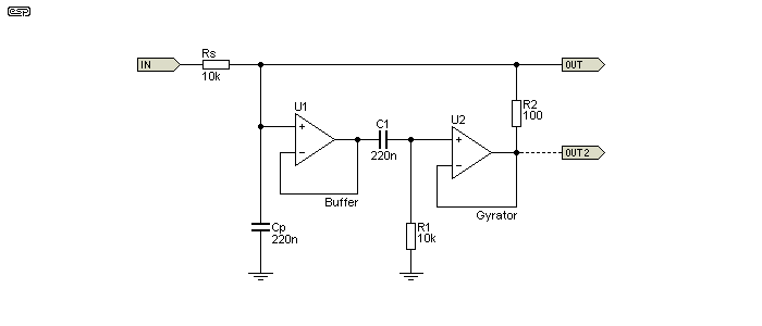
The relationship between the capacitive and inductive reactance and the feed impedance all work together to determine the circuit's Q and insertion loss (which reduces the peak amplitude). If capacitance is changed by itself, Q is affected, and the same happens when the inductance is changed. So, as it turns out, eliminating the effect of the damping resistor isn't as useful as it seems at first. It's still worth including though, because it's definitely beneficial if a higher than 'normal' Q is necessary. Inductance (2.2H for the values shown) is calculated in the same way as for a 'normal' gyrator ...
L = C1 × R1 × R2
XL = 2π × fo × L
Q ≈ Rs / XL
Q is approximated by Rs (Source resistor) divided by the reactance of Cp or L1 (the gyrator). At resonance, the reactances are equal but opposite. For example, if the capacitive and inductive reactance are both 3.18k (the case for the circuit shown), the Q of the tuned circuit is 3.145 (Rs / ( XC). However, real life isn't perfect, so the Q is always somewhat less than the calculated value. The peak amplitude is -0.83dB. The frequency is 228.7Hz, set by Cp, C1, R1 and R2. Increasing the value of Rs increases Q, but also increases the insertion loss. For example, if Rs is changed to 22k, the actual Q increases to 5.73, and insertion loss increases to 1.73dB.
As with any other LC resonant circuit, the impedance is inductive below resonance (so impedance rises with increasing frequency), resistive at resonance, and capacitive below resonance (impedance decreases with increasing frequency). The Q of the circuit is of no consequence at resonance, only above and below. A high Q circuit has an initial rolloff that's faster than a lower Q circuit, but both eventually end up being 6dB/ octave (for a single tuned circuit). The ultimate attenuation of low frequencies is determined by the coil resistance (equivalent to R2).
This isn't an especially common variant, but it may turn out to be handy for some tasks. The elimination of the parallel resistor provides a useful increase of system Q. Note that the Figure 13.1 circuit can be used for both series or parallel tuning (notch or bandpass respectively).
There are two other 2-opamp gyrators, with the first one (Figure 13.2) being something of a mystery. I became aware of it from a circuit sent to me by a friend, and it has some significant advantages over the more common version shown above. In particular, the output impedance is low (nominally zero ohms), and it can be made to have a very high Q. There is no internal gain which could cause premature overload (clipping), but the tuning formula is dodgy. I could find no 'official' formula (and no information other than in the referenced document [ 12 ]), but I was able to work out a formula with a 'fudge factor' (aka a 'constant') that seems to be accurate ... provided R3 and R4 are 10k. If they are a different value, you need to make a correction.
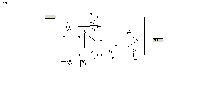
With values as shown for R3 and R4 (10k), the (approximate) inductance is determined by ...
L ≈ Rt × Ct × ( ½R4 )
L ≈ 10k × 22n × 5k ≈ 1.1H
The value of 5k (½R4) is the 'constant' that I determined empirically. As noted above, it only works when R1-R4 are 10k, so you'll have to re-calculate it if you decide to change these values. It turns out that the constant is half the value of R3 and R4, and they must be the same value. While it may appear that R3 and R4 are effectively in parallel, this isn't the case. However, using a constant value that's half that of R3 and R4 works in order to determine the inductance. There's no requirement for R1 and R2 to be the same value as R3 and R4, but there's also no reason to make them different. The formula shown has been tested against a large number of filters in the referenced document (the published schematic uses 40 individual filters!).
The ratio of R3:R4 should be maintained at 1:1. If R3 is reduced in value (relative to R4), the Q is increased, but if you go just a little too far the circuit will oscillate. R3 does not change the frequency, but R4 does. I suggest that you use 10k for each if you wish to use the circuit for anything.
Note that the Figure 13.2 circuit is a bandpass type when Cp is added, and it cannot be rearranged to form a band-stop (notch) filter. Without Cp it performs like an inductor, having zero output at DC and an impedance that rises at 6dB/ octave with frequency (as expected). With Cp included as shown, the resonant frequency is 1,023Hz ...
f = 1 / ( 2π × √ ( L × C ))
f = 1 / ( 2π × √ ( 1.1 × 22nF )) = 1.023 kHz
Or using a single formula ...
f = 1 / ( 2π × √ ( Rt × Ct × 5k × Cp ))
f = 1 / ( 2π × √ ( 10k × 22n × 5k × 22n )) = 1.023 kHz
As a bandpass filter, it uses more parts than a MFB (multiple feedback) filter, but it's far more versatile. The frequency can be changed by altering Rt with a pot, and Q is independently adjustable by varying Rs. While it uses twice as many resistors and opamps, that's more than compensated for by the high (and easily adjustable) Q available, and the ease of wide-range tuning.
With any bandpass filter, determining the Q is generally a requirement as well. It's not hard, but providing a single formula isn't likely to be helpful. The first task is to determine either the capacitive reactance (XC) or inductive reactance (XL). At resonance, they are equal, so I'll use XC ...
XC = 1 / ( 2π × f × C )
XC = 1 / ( 2π × 1,023 × 10n ) = 7.071 kΩ or ...
XL = 2π × f × L
XL = 2π × 1,023 × 1.1 = 7.070 kΩ
The small difference between the two impedance calculations is simply the result of not using all decimal places, and is not an error. The Q is simply (and approximately) the series resistance (Rs) divided by XC or XL, which works out to be about 14.14. The calculation will almost always be a little different from the measured value, but bear in mind that actually taking a measurement with any degree of accuracy is very difficult with high-Q filters. I measured the Q (using the simulator) to be 14.4, so the error is small, and for almost all applications it's insignificant. A project version of this circuit is shown in Project 218.
Using JFET input opamps (e.g. TL072), you can get an astonishingly high Q. If Rs is made 1MΩ, the Q at ~1kHz is over 150 - that's a -3dB bandwidth of only 6.7Hz. It's unlikely that you'll ever need that much, but it's there if you want it (depending on component thermal stability). The only capacitors that might be stable enough are polystyrene, but with a -3dB bandwidth of less than ±3.5Hz in 1,000, that's still a big ask.
This particular gyrator verges on being 'magic'. It can be tuned over a two octave range with less than 2dB variation in gain, but the Q changes. This is common with all gyrators because there's an inevitable compromise between XL and XC that is difficult to balance out. The fact that it can have a Q that's far greater than 'conventional' gyrators makes it ideal for a sharp filter to all but eliminate distortion from an audio oscillator. However, you will be limited to spot frequencies because the Q can be so high that only a few Hz difference between the oscillator and filter can reduce the output level dramatically. It can also be used to isolate individual harmonics, something I have tested and it does a fine job.
A recent search shows that the original circuits seemed to have vanished (the designer died in 2011), and while the website continues [ 12 ], the schematics are buried and difficult to find. The original source of the gyrator itself remains a mystery. The first stage is a NIC (negative impedance converter) followed by an integrator, but it's the feedback that creates the 'inductor'.
Another variant is the 'classic' GIC (aka FNDR) filter, shown next. The advantage over the Figure 13.2 circuit is that it uses fewer resistors, but it doesn't have low output impedance. It's capable of very high Q (over 100 is easy to achieve), and the Q is set by Rs - the series input resistance. Unfortunately, getting a high-Q bandpass filter (achieved using Cp) requires that Rs is a high value, meaning that the output impedance is also very high, and it needs to be buffered with another (preferably JFET input) opamp to be useful.
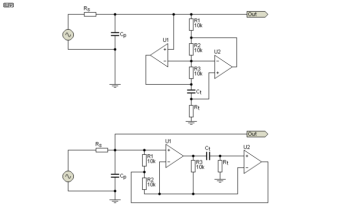
I've shown the same circuit twice, with the upper drawing showing the standard way the circuit is drawn, and the lower drawing uses a more 'conventional' layout that's easier to follow. No 'fudge factor' is needed here, and the inductance of the gyrator is determined by the formula ...
L = √ ( Rt² × Ct )
With 10k for Rt and 10nF for Ct, the inductance is 1 Henry. Like the Figure 13.2 circuit, this only holds true if all other resistors are maintained at 10k. Rs (the input series resistor) determines the Q. For example, if Cp and Ct are both 10nF, and Rs Rt are both 10k, the resonant frequency is 1.59kHz, and the Q is 1. That means that the bandwidth (-3dB) is the same as the resonant frequency, in this case both are 1.59kHz. If Rs is increased to 100k, the Q is raised to 10, but (hopefully obviously) the load impedance needs to be many times that (> 1MΩ) or the Q and output levels are reduced.
Like most FNDR filters, the Figure 13.3 circuit has internal gain. This can cause problems regardless of the source resistance (Rs), as the internal gain can be up to ×10 (20dB). Overload is likely if the input signal level is over 1V peak (700mV RMS) or so. This most likely when the circuit is used as a tuned circuit (including Cp). In general, Rs should not be less than 5k if 10k resistors are used elsewhere.
When used as bandpass filters as shown in the three circuits above, the resonant frequency is determined by the parallel capacitance (Cp) and the effective inductance. The formula is ...
f = 1 / ( 2π × √ ( C × L ))
Of these filters, the Figure 13.2 version has distinct advantages. There is no possibility of internal gain causing premature overload, and it has a low output impedance. This removes any requirement for a buffer to drive external circuitry (including summing amplifiers). The lack of a sensible tuning formula is no great cause for alarm, provided you use 10k resistors. Otherwise, you can work out a different 'fudge factor' to suit a value of your choosing.
One of the most common uses for gyrators (in audio) is the graphic equaliser. By using a series resonant circuit, the impedance is minimum at resonance, and this is used to modify the gain of an opamp configured in the same way as a Baxandall tone control, but with anything from 5 to 31 sections. Early graphic EQ circuits used 'real' inductors, which meant they were very expensive, and subject to radiated magnetic fields from nearby transformers. In the interests of brevity, I've only shown a 1 octave band equaliser, using the 'universal' frequencies that are used by almost every manufacturer.
Graphic EQs vary, and can be 2 octave (5 EQ sections), 1 octave (10 sections), ½ octave (20 sections) or 1/3 octave (31 sections). However, if you build your own, you only need to include the filters you need, depending on the frequencies you wish to control. They don't have to be contiguous, nor do they need to align with the 'normal' frequencies used. The circuit must be driven by a low impedance source, such as an opamp unity gain buffer (U1). The values indicated by '*' are repeated for each filter.
Even a 1 octave graphic EQ is not for the faint-of-heart, especially for a one-off. Of course they can be purchased cheaply enough, but finding spare parts for an older unit can be challenging. If you buy one new, it will almost certainly use SMD parts, making repairs very difficult should it break down (and getting replacement pots will likely be next to impossible). The table below shows the values that are used with the Figure 14.1 equaliser. R1, R2 and C1 determine the inductance of the gyrators. I have made adjustments to the original design to get closer to the required frequencies (some had quite significant errors (up to 10%).
| fo Nominal | C1 * | C2 * | R1 * | R2 * | Inductance | fo Calculated |
| 32 | 120 nF | 4.7 µF | 75 kΩ | 560 Ω | 5.04 H | 32.7 Hz |
| 63 | 56 nF | 3.3 µF | 68 kΩ | 510 Ω | 1.94 H | 62.9 Hz |
| 125 | 33 nF | 1.5 µF | 62 kΩ | 510 Ω | 1.14 H | 121.7 Hz |
| 250 | 15 nF | 820 nF | 68 kΩ | 470 Ω | 479 mH | 252.4 Hz |
| 500 | 8.2 nF | 390 nF | 68 kΩ | 470 Ω | 262 mH | 498 Hz |
| 1k | 3.9 nF | 220 nF | 62 kΩ | 470 Ω | 113 mH | 1.0 kHz |
| 2k | 2.2 nF | 100 nF | 68 kΩ | 470 Ω | 70 mH | 1.9 kHz |
| 4k | 1 nF | 56 nF | 62 kΩ | 470 Ω | 29 mH | 3.9 kHz |
| 8k | 510 pF | 22 nF | 68 kΩ | 510 Ω | 18 mH | 8.0 kHz |
| 16k | 330 pF | 12 nF | 51 kΩ | 510 Ω | 8.6 mH | 15.7 kHz |
Because each frequency is double the one before, it figures that inductance and capacitance will halve for each successive band. There are errors in the values which will shift the frequencies slightly from the design point, but this is not an issue. The circuit (like all EQ stages) is intended for response manipulation, and is not intended as a precision filter. Some of the values are non-standard, which is always a problem when you have so many filters. Capacitors aren't available as standard with neatly doubled/ halved values, so parallel combinations will be needed in a few places to get the right value. I leave this to the reader, especially since this is not a construction project, but is intended to demonstrate designs and ideas.
With all values as given in the schematic and table, maximum boost or cut would be quoted as ±10dB, although it measures about ±11dB. To get ±12dB, R2 and R3 (both 2.7k in the equaliser section) can be increased to 5.6k, but this will result in greater noise. The nominal Q is 1.57 for the filters shown, although it does vary a little in reality. Q isn't shown in the table, but a reasonable approximation is to use the formula ...
Q ≈ 2π × fo × L / R2 Which can also be written as ...
Q ≈ XL / R2 = 1.51
Q ≈ 2π × 1k × 113m / 470 = 1.51
The formula shown differs from that shown in most reference material, but is closer to reality. A simulation shows that the actual Q is somewhat lower, and I measured it in the simulator as 1.48 to 1.55 for a couple of different frequencies. Being a rather tedious process, I didn't test all filters. Given the nature of any graphic equaliser, small variations in Q don't amount to much.
You always need to consider the noise gain in circuits such as this. With 10 × 10k pots, the noise gain of U12 is 16dB, even though the audio gain is unity when all pots are centred.
The gyrator is a cost-effective and convenient way to build a tuned circuit or to replace inductors in audio frequency circuits. It's not at all difficult to get very high Q filters, and it's very easy to obtain a Q of 4 as required for a 1/3 octave equaliser. Expecting a Q of more than 10 usually requires a dual-opamp version, but for audio applications it's not necessary and is almost always undesirable anyway. Very high Q filters are simply never needed for audio, but can be useful in other audio frequency applications such as analogue test and measurement systems.
NIC/ GIC and FDNR gyrators offer advantages and disadvantages, but are unlikely to be encountered in any practical circuit that you might find. They are very capable, but are generally too complex for any DIY project, and will also be extremely difficult to debug should something go wrong. They have been included because they are interesting, but I don't expect to include an FNDR in one of my projects any time soon (i.e. never). GIC gyrators are much easier, and obtaining a Q of more than 20 is fairly straightforward.
A Q of only ten means that the bandwidth is 1/10th the centre frequency. At 1kHz, that means the signal is 3dB down at (roughly) 951Hz and 1,051Hz, a bandwidth of only 100Hz. To get a higher Q and steeper slopes at the frequency extremes, you can use two filters in series. In some cases you may only need a (close to) ideal inductor, but remember that most 'simple' gyrators are ground referenced, so they cannot be used in series with the signal, only in parallel. An FNDR gyrator can emulate series inductors (see Figure 11.1.1), but they are the most complex form of gyrator and are difficult to design.
As noted in the introduction, I have avoided using complex formulae and other 'high level' maths, because in my experience it's rarely necessary and almost never gives a better understanding than proper examples, waveform traces and down-to-earth explanations. For those who want to play with the maths involved, there are plenty of sites on the Net that use this approach. None that I saw will provide the level of understanding that I've shown here, and for the most part are more likely to cause confusion. A purely theoretical examination of any circuit (and assuming ideal components) is usually not very useful, but that is the approach taken by many of those who offer explanations.
Some of the information might appear to be very comprehensive (for example [ 8 ]), but may be factually wrong in some areas. It is largely pointless unless you are involved in pure mathematics and are willing to accept a gyrator as a theoretical lossless component - which it is not! It can be a real 'component', and it will have losses and limitations. Additional circuitry that removes the losses only works within the boundaries of the opamps used, and may cause more problems than it solves.
There are many university papers that discuss the theory of gyrators, and some include circuits for practical demonstrations. One of these was the basis of Figure 18, but the potential pitfalls were not examined thoroughly enough for it to have been particularly useful as a demonstration. The idea was for students to discover the pitfalls for themselves, but in my view that expectation would often lead to exasperation and confusion because some of the limitations can be too subtle for the inexperienced to notice.
I hope that this article has been useful, and has provided a good insight into gyrator operation. It's always difficult to get the right balance between simplicity and complexity to arrive at something that provides good understanding without being overwhelming. Since all circuits shown in this article will work, I encourage those who want to know more to build and experiment.
Several references were used while compiling this article, and are combined with my own accumulated knowledge and/or resulting from the many simulations done in the production of this article. Material herein and some of my accumulated knowledge is due to the following publications ...
 Main Index Main Index
 Articles Index Articles Index
|