
|
|
| Elliott Sound Products | AN-010 |
 Main Index
App. Notes Index
Main Index
App. Notes Index
The analogue telephone system is commonly known as the PSTN - public switched telephone network, but is also called POTS - plain old telephone system. It is characterised by the operating voltage of 48V DC supplied from the exchange when the phone is 'on-hook' (not connected to the local exchange), and around 5-12V when 'off-hook' (during a call). It's a 2-wire system, with simultaneous bidirectional communication. Dialling is either by DTMF (dual tone multi-frequency, aka 'Touch Tone' in the US) or (rarely now) pulse (aka decadic), where the line is connected and disconnected to create pulses that signal the dialed number to the exchange. One pulse signals the digit '1', two pulses for '2', etc. The details for DTMF signalling can be found on the Net if you want to know.
Ringing is provided by an AC voltage superimposed on the line, at a frequency of about 20Hz, and with a voltage of 90V RMS. The ring current is 'cadenced' which is to say it's interrupted to create a ringing pattern. This differs in different countries, but part of the reason is to minimise the risk of electric shock. When the handset is lifted (off-hook), the exchange sends 'dial tone' to signal to the user that dialling may commence. Like the ringing cadence, dial tone differs in different countries. When the called number is ringing, 'ring tone' is sent to the calling party to indicate that the remote phone is ringing. If the remote phone is busy (off hook), the caller hears a 'busy' tone.
While the specifics of all these functions are subject to individual country's standards, the principle is unchanged. Mobile ('cell') phones operate completely differently, and are not included in the above. Communication (dialling, speech, etc.) are all digital, dial tone is usually not provided with modern systems, but ring and busy tones are still supplied so the caller knows that the call did or did not get through. In some cases, special tones are used to signal network congestion when no spare radio channels are available or the exchange is at capacity.
While the PSTN is being superseded worldwide by mobile/ cell phones and VOIP (Voice Over Internet Protocol), the principles are no less interesting. They are also no less important, but many of the principles are (or can be) 're-purposed' to suit particular requirements. One of these is 'talk back' radio, where the requirement for a hybrid are still essential, regardless of the type of phone system in use. The adventurous experimenter may also find other uses for a system that can use full duplex (simultaneous 2-way information over a single pair of wires). To be useful, the individual signals need to be separated at each end, and that's what a hybrid does.
This article does not cover the signalling or power systems, or the main infrastructure, but concentrates on one small but vital part of the system as a whole - the hybrid circuit (as it is commonly known by telephone engineers). A hybrid is used to convert a bidirectional 2-wire circuit into separate 'send' and 'receive' channels, commonly known as a 4-wire interface. More information is available in Reference 4, which is a fairly comprehensive overview. It's based on the US system, but those used worldwide are similar, and the general ideas are representative of other systems.

NOTE: It is an offence in most countries to connect non-approved equipment to the phone network, and the information here is not intended to allow you to make any connection to your phone line. This material is for your information only. Obtaining approval is a costly exercise and it's highly unlikely that any 'home made' equipment would even be considered.
Hybrids are the heart of the analogue telephone system. They allow two people to speak and listen simultaneously over a single pair of wires, with little or no interaction. This Application Note is not about producing a telephone system or even a part thereof, but is intended to introduce the concept of a hybrid, and explain how it works. In one form or another, hybrids have been used since the early telegraph days, and they are an essential part of the telecommunications system.
You can also build a pair - not because it's inherently useful for anything, but to experiment and learn. There's nothing especially critical about the principle, but it does become a lot harder (and there is inevitable degradation) when transformers are included. While these are not used in your home telephone, most exchanges (aka central offices) use transformers to ensure complete isolation from the outside world and all the dangers it represents.
Using the techniques shown here, you could build a nice intercom or similar, but they are so cheap that no-one would bother. It's much better to build it for the pure sake of doing so, and to learn about techniques used in signal processing systems. You don't even need to physically build anything if you have a circuit simulator - this lets you do lots of 'what if' experiments without wasting any parts.
One very common application of stand-alone hybrids is in the radio broadcast system, where callers are broadcast during conversations or (generally one-sided) debates with the on-air 'personality'. There is a considerable amount of additional circuitry necessary to interface with an analogue telephone circuit, and this is not covered here.
The phone system has had a great deal of influence over the audio standards that have developed over the years. A vast number of things we use daily in audio are the result of inventions and standards developed by telephone research laboratories. Bell Labs, which has been part of many different phone companies over the years, is preeminent amongst these. Negative feedback, the decibel system, transistors, and many other developments we take for granted all came from Bell Labs. Many of the things we take for granted in audio came (perhaps indirectly) from the phone system, for example the 'phone' plug as used on guitar amps (tip/ sleeve) and for headphones (tip/ ring/ sleeve) came directly from the manual telephone exchanges (central offices) of old.
The idea of 600 ohm balanced lines also came directly from the phone system - these are the mainstay of all interconnects used in recording and PA systems. For many years, radio stations relied on phone lines for their live broadcasts, and even for connection between the studio and transmitter, as well as callers going to-air as described above. Most outside broadcasts are now handled by portable microwave links, but a fixed line is still one of the most reliable connections known.
If any 2-wire full duplex (meaning that traffic can pass in both directions simultaneously) analogue line requires amplification, this can only be done after separating the send and receive signals into separate pairs. This is shown in Figure 1. If a single amplifier were used, one direction would be blocked. With two amplifiers but no hybrid, the amplifiers would simply oscillate, wiping out all communications.
Figure 1 - Amplifying A Bidirectional (Duplex) Pair Signal
The scheme shown above is very common. Care is needed to ensure that the amplifier gain is not too high, otherwise the system will still oscillate. Gain must be at least 6dB lower than the worst-case transhybrid loss (see below for an explanation of this). Most digital signals are transmitted as 4-wire (separate send and receive pairs). Amplification may not be necessary for short lines, and the digital signal is 'reconstituted' to produce clean transitions between the two digital levels. These may be a voltage signal, or light if a fibre-optic cable is used.
The terms used should not be taken literally. A 2-wire system may only use 1 physical wire, with earth/ ground being used for the return. Likewise, 4-wire systems may only have 3 physical wires ... earth (ground or common), transmit and receive. The primary point of difference is that a 2-wire system is full duplex - traffic (voice or data) can travel in both directions without interaction.
4-wire systems are simplex - data travels in one direction only, and each direction (in or out) has its own separate circuit. While the 4-wire circuit is much better, having zero interaction regardless of termination impedances or other issues, it uses twice as much cable. This was not an option when telephones first became available, so the 2-wire system was used to minimise cable usage but still provide an acceptable service. Many early telegraph and telephone systems used a single wire, with the return path provided by the earth (as in the planet).
The analogue telephone systems worldwide rely on a single pair of wires for both transmit and receive of speech or modem data. DC (48V nominal) is also sent along the same pair, allowing the exchange to provide power to the telephone. This is important in case of blackouts (and even more so before even electric lighting was readily available), since the phone can still be used. The standard wired analogue telephone system is probably one of the most reliable pieces of engineering on the planet, and although other methods for communication are becoming more popular, none can approach the reliability of the wired phone.
The systems have been gradually changing for a long time, but the basic requirements have never changed. It is still possible to use a 70 year old rotary-dial telephone on the latest exchange equipment, and it will work just fine. This level of long-term compatibility has not been achieved with many products - I can't actually think of a single one that offers the same level of compliance as the humble telephone.
Figure 2 - Demonstration Hybrid Pair
It might look complex, but it isn't really. The section on the right is one 'station', and that on the left is another. Each can transmit information to the other, with the level at the Out terminal of the sending station being suppressed by at least 40dB. This is adjustable with VR1 on each section. The signal transmitted (via the In terminal) arrives at the Out terminal of the other station, attenuated by 6dB - half the level. Needless to say, this isn't an issue, since the transmit level simply needs to be increased (or the receive gain increased) to compensate. The two stations are connected by a line, which may be ordinary twisted pair, and somewhere between a couple of metres to a kilometre or more in length.
If you look at the circuit closely, and ignore the send buffer (U1Bx), you'll see a modified version of the standard balanced input opamp stage. Signal is applied to both opamp inputs when sending a signal to the line. Both inputs will be at the same voltage (by adjusting VR1), so there will be no signal from the output. The total value of VR1 and R2 will be about 7.25k to achieve balance. When a signal is received from the line, only the negative input has that signal present, and it is amplified (by -1) and appears on the output terminal.
Once the system is installed, simply inject a tone into one of the hybrids, and adjust VR1 to get the minimum level from the Out terminal. Do the same for the second hybrid. If you vary the frequency, you will find that the maximum rejection changes, but with a short line the variation will not be great. In a system with a short line (less than 100 metres), the rejection will be at least 40dB.
It is customary to refer to impedance balance and unwanted signal rejection in terms that cannot be considered intuitive unless you've worked within the industry. The telephone line is a complex impedance, and consists of resistance, inductance and capacitance. The US and a few other countries simply designate the impedance as 600 ohms, but in most others the 'official' impedance is an attempt to consolidate the cable and end-equipment parameters. In Australia, the impedance is 220 ohms, in series with the parallel combination of 820 ohms and 120nF. The UK and Europe also use complex impedance networks, but all are different. While this is extremely puzzling (after all, cables used for telephones are not all that different), it's simply a fact of life. In reality, it doesn't make much difference - all perform roughly equally, including 600 ohms resistive (although this is commonly modified with extra resistance and the addition of some capacitance).
Because the sending impedance is determined to be a particular value to match the cable, the receiving equipment (along with the connecting cable) must have the same impedance. If this is done well, there is a minimum of echo returned to the phone line and exchange, and the minimum disruption to long distance calls. This is actually an extremely complex topic, and it will not be discussed in any further detail. Suffice to say that the CPE (customer premises equipment) needs to be able to satisfy a minimum impedance standard before it's allowed to be connected to the phone system. This applies almost everywhere, world-wide.
Rather than attempt to state the impedance in terms of reactance, resistance or measured impedance, it is measured by a meter called a return loss bridge. This gives a reading of the impedance imbalance in dB. A perfectly matched impedance has a return loss of infinity, but even as little as 20dB can be surprisingly difficult to achieve in the real world. Figure 3 shows the Australian phone impedance as part of a return loss bridge, along with a graph showing the return loss when connected to a (slightly) mismatched load and artificial line. Remember that the ideal case is a return loss of infinity, but even a relatively small mismatch is sufficient to reduce the return loss dramatically. A good design is expected to be able to meet the requirements with various line lengths - including zero. The return loss bridge is shown here with the Australian standard telephone impedance, but any other impedance (including a 600 ohm resistor) can be substituted.

Figure 3 - Return Loss Bridge & Graph
Measurements are shown from 200Hz to 4kHz. The telephone bandwidth is deemed to be from 300Hz to 3600Hz, and this has been the standard for a very long time. The upper limit is now strictly enforced because so much of the network is digital. The sampling rate is only 8kHz, so 3.6kHz gives an acceptable safety margin before digital aliasing becomes a problem. It is extremely difficult to get a good return loss below 300Hz, because so much equipment uses transformers. With limited inductance imposed by small size, phase shift makes a good impedance balance almost impossible at low frequencies. Some countries impose return loss limits at frequencies below 300Hz, but they are usually fairly generous (perhaps 10dB or so).
The next figure of merit is known by many names, but the most descriptive is simply 'transhybrid loss'. This is a measurement of the amount of signal picked up at the receive port, while it is transmitting signals within the allowed frequency range. An ideal hybrid will have an infinite transhybrid loss, but this is influenced by the line impedance. A good hybrid will achieve around 25-30dB, but for telephones it is common to use a lower value. This gives the person speaking some of their own voice in the earpiece, so they can hear themselves at a low level. This is called 'side tone' in telephony, and provides a level of confidence that the phone is working. Humans expect to hear themselves when speaking, and the phone system is designed to make sure this happens.
Figure 4 - Transhybrid Loss & Graph
Figure 4 shows the same hybrid and artificial line as used in Figure 3 (terminated with the Australian standard impedance), but this time measuring the transhybrid loss. Although the transhybrid loss was measured at over 50dB with a perfectly matched line impedance, this is degraded significantly by a comparatively small mismatch.
Unfortunately, but by necessity, the transhybrid loss is affected by the degree of line matching (return loss). If there is a poor match, both return and transhybrid loss will be compromised. Excellent results have been achieved by telephone systems the world over, despite the huge variations met in practice. Phone lines can range from less than 100 metres to several kilometres, so will have dramatically different resistance, capacitance and inductance between the phone and the exchange. The impedance refuses to conform to legislation or standards bodies, and rather perversely chooses to obey the laws of physics instead.
Before we had any form of electronics, we had a phone system. Early systems had to rely solely on their own ability to generate a high level signal from a microphone. Carbon mics were the choice, because no other microphone is capable of producing such a high level, low impedance signal. Carbon mics actually have gain - enough to cause feedback if the mic is placed next to an earpiece. Because of this, a basic hybrid was essential to prevent the phone from squealing. Earlier systems used a separate mouthpiece and earpiece, but to enable a single handset with both required a system that provided electrical signal isolation.
The earliest hybrids consisted of a coil with multiple windings - it may be considered as a transformer or an inductor, but in many cases it's really an autotransformer, with all windings joined at some point. Figure 5 shows one of the arrangements that were used - the hookswitch and ringer circuits have been omitted for clarity. Note that in all cases, the resistance of the transformer windings must be considered when determining impedance matching.
Figure 5 - Single Transformer Hybrid
The dots indicate the winding start, needed because the direction is important. While it may not look very impressive, the single transformer hybrid is capable of extremely good performance. In exactly the same way as an active hybrid (using opamps or digital signal processing), the performance in both directions is degraded if the line impedance does not match the design value. The impedance matching network must be located in the position shown. Theoretical transhybrid loss (with a perfectly matched impedance) is infinite, but this can never be achieved in practice. Maximum return loss is achieved with the load impedance (at the receive port) as high as possible.
This arrangement was used in huge numbers, as it was the heart of almost all non-electronic telephones. See Figure 7, and you can see the exact same arrangement, although the matching impedance is different. No part of the circuit may be earthed, with the exception of the receive winding. While not a problem for a telephone, this makes it unsuitable for fixed equipment where an earth is required for electrical safety.
Figure 6 - Dual Transformer Hybrid
The dual transformer version has the benefit that all ports (line, transmit and receive) are isolated from each other. This is of no consequence in a telephone, but may be important for some exchange equipment. While this version is still used (transformers are still available), it is uncommon in general phone circuits. Performance can be extremely good, but compared to IC replacements that are now very common, the space and expense make it unattractive.
Termination impedance is rather interesting. The terminating impedance shown affects only the transhybrid loss, and has no influence at all on the impedance presented to the 2-wire port. The proper impedance is set by using a modified network in series with the transmit port, and in parallel with the receive port. In this respect, this hybrid is unique, in that return loss and transhybrid loss are effectively independent of each other. However - both are affected by the actual external impedance, so an artificial line will mess up both. This is in deference to the 'no free lunch' principle. 
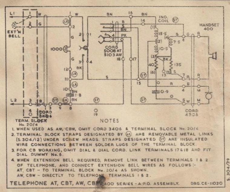
Figure 7 - Schematic of Old Rotary Dial Telephone
The above is a scan of the little piece of paper that was inside an old telephone (as supplied by the Australian PMG (Postmaster General, aka APO - Australian Post Office), and is the actual schematic (with options) of this series of telephones. The phone itself is one of the old black Bakelite types - very retro, and still functional despite the fact that it's at least 50 years old. Remember to add the winding resistance to any external resistances when determining impedances. The hybrid is a single transformer type as shown in Figure 5, but is wired somewhat differently.
| Main Index
App. Notes Index |