
|
|
| Elliott Sound Products | Project 145 |
It is pretty much standard fare that guitar amps will have effects and/or different channels that need to be switched - often in the middle of a song. Running long leads from the amp to a pedal board is one way, but that's almost designed to pick up noises and affect the top end. Relays are used in some amps, but while these are almost perfect switches, they are also a cause for much grief in a combo amp. The vibrations from the speaker can often cause the relay contacts to 'chatter', and this causes most unpleasant distortion.
Some manufacturers of commercial amps have gone to great trouble to isolate the relays from the chassis to reduce (or hopefully eliminate) contact chatter. Some techniques work, some don't. If the relay sub-assembly's resilient mounts become hard from constant heat (a major issue with valve amps), the relays start chattering and it can be difficult to figure out exactly what's causing the horrible distortion. It will only happen when the amp is being used normally, and often can't be reproduced on the work-bench.
A better solution is to use LED/LDR optocouplers, and there are a few manufacturers who have done just that to get around the relay problem. This project describes a DIY optocoupler switching system that can be added to any commercial or home-built guitar amp, and predictably I suggest Project 27 as an ideal candidate. The other benefit of the optocouplers is that the switching is 'soft' rather than instantaneous, so the likelihood of clicks and pops as you change channels is greatly reduced.
There are two options for switching an audio signal using optocouplers, series and parallel. To get the maximum benefit, I propose the use of both, so that the switching is as fast as possible, and provides the maximum attenuation of the unwanted signal. Because Vactrol™ optocouplers such as the VTL5C4 are not inexpensive and may be hard to obtain for many constructors, you can make your own optocoupler using an LED and an LDR in a light-tight enclosure made from heatshrink tubing (see below).
The performance of the ready-made or home-made versions is likely to be very similar, so changes to the circuitry will range from none at all to minimal. I have used the home-made versions in Project 53 and Project 92, and the VTL5C4 is specified for Project 137. Naturally, the home-made optocoupler can replace the VTL5C4 and vice versa.
The one minor gripe with LDR based optocouplers is that they switch off s-l-o-w-l-y, taking about 1.5 seconds to reduce the level by about 16dB (from 1V RMS down to about 150mV RMS). However, they switch on in less than 3ms, and the signal is increased from nothing to maximum over this time - rather like an extremely fast volume control. This relatively fast (but not instantaneous) volume change ensures that the switching is effectively silent, with no transient noises as you will get with a relay.
Figure 1 - Series And Parallel Optocoupler Switching
Predictably, the series switching passes a signal when the LED is turned on, and the parallel switching passes a signal when the LED is off. This makes it possible to combine the two so that we get reasonably fast switching for both on and off cycles. We want to minimise signal 'leakage' when the circuits switch, where both signals are present at the same time. Any leakage should not be audible while playing.
The tests I ran used a VTL5C4 optocoupler, and both the above versions were verified. In each case, the LED was powered as shown, giving a LED current of 3.8mA. It's possible to use a higher LED current, but very little is gained. The measured test results all used an input voltage of 1V RMS, and the measured outputs were ...
Series LED Output Parallel LED Output Off < 2mV Off 1V On 986mV On 20mV
In both cases, when the LED is turned off, there is a slow return to the normal high resistance of the LDR. The effect is much more pronounced with the series connection than with parallel, because of the loading resistor (R2). A larger loading resistor causes the output to return to normal faster, but will also allow more signal through when the LED is off and increases overall circuit impedance. By using two LED/LDR units it is possible to get a faster response, but at the expense of circuit complexity (and the cost of the LED/LDR units themselves of course).
In a great many cases, we don't care too much if the response is fairly slow. Provided there is still a signal from the amp that's not at a dramatically different level, the slow switching does no real harm. If two optocouplers are used as shown in Figure 2, the response is almost certainly fast enough for any player. The two opamps might seem like overkill, but the flexibility they add is worth the small extra. Power supply connections (typically +12V and GND) are not shown. The input signal (VCTL) will normally swing between zero volts and +12V. The reference voltage (VREF) can be derived by using a pair of 1k resistors between +12V and GND, and the centre-tap will provide +6V. Bypassing isn't really needed, but feel free to use a 10uF cap between VREF and GND if you think you'll be happier.
Figure 2 - Series-Parallel Optocoupler Switching
By using two optocouplers as shown, the switching speed is improved. When the upper LDR is illuminated, the signal passes through the switch with little attenuation. When the lower LDR is activated, the signal is reduced very quickly. Reactivating the upper LDR does not switch the signal back on as quickly as you might expect, because the lower LDR is still conducting (remember, they turn off quite slowly). The switching times are shown below. While both LDRs are conducting, the input impedance of the switch is quite low - typically around 1k. The signal source must be low impedance, and also must be capable of driving a low impedance without distorting.
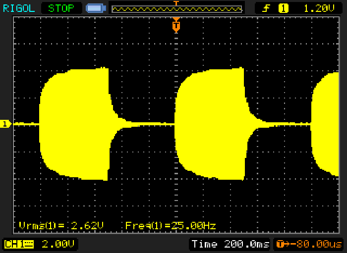
Figure 3 - Series-Parallel Optocoupler Switching Waveform
For the above waveform, the two optocouplers were driven with a 10Hz signal that turned the LEDs on and off. The input was a 500Hz sinewave at around 1.5V RMS. Turn-on and turn-off times are easily seen, and the signal reaches within 1dB of the maximum within 200ms. When switched off, the signal is ~20dB down from maximum within 100ms. While this might seem far too slow to be useful, it's not, in fact it sounds just right in a listening test.
The next (and generally most useful) option is to use the optocouplers to switch between two input signals. For a guitar amp, the input signals will typically be the outputs of two preamps which can be set up completely differently. To achieve this, we simply re-organise the two optocouplers. The rest of the circuit is unchanged.
Figure 4 - Optocoupler Channel Switching
You'll notice that there are only two optocouplers used for channel switching and you may have been expecting more. However, the two optos shown here are working almost identically to those in Figure 2. The only difference is that rather than one input being GND, it has a signal on it (or at least is connected to the output of an opamp in the preamp circuitry). I was so unsure how it would sound that I set up a test with two oscillators, each producing a different tone - one to each LDR switch. I listened to the output as I switched from one to another, and the changeover is perfect, and almost inaudible. Even two sinewaves at exactly the same frequency gave a barely audible result. Sinewave testing is one of the most revealing and difficult, because we hear (and expect to keep hearing) a pure tone with no artifacts.
The switching circuit has been shown using LM358 dual opamps, and you need to use the specified type. This is because the LM358 can switch its output to the negative supply (within a few millivolts). Most other opamps can't do this, and the LED may have a very small forward bias even when it's supposed to be turned off.
You can also use CMOS logic if you prefer. Note that the output of CMOS is not capable of sourcing or sinking very much current, and even with a 15V supply you can only get ~3.5mA output current. However, this is enough, and a single 4069 (or 40106 Schmitt) hex inverter can drive three separate switching circuits. The alternative circuit is shown below.

Figure 5 - Optocoupler Channel Switching Using CMOS
There is no difference between the performance of the two variants, because the LDRs are much slower than either of the drive circuits. Note the zener diode (D1), which it to prevent any stray voltage spikes from damaging the CMOS input. CMOS ICs are very sensitive to static discharge and the zener is cheap insurance. You can also use transistor drive or even a PIC microcontroller if you want to. Since a PIC runs at 5V, you need to change the LED drive resistors to suit - around 1k will be fine (LED current of ~3.4mA). Although the apparent simplicity of a transistor drive circuit is appealing, it actually uses more parts and is not quite as simple as it may seem.
Since the VTL5C4 and its ilk are not inexpensive, you might prefer to 'roll your own' optocouplers. You will need to obtain a suitable quantity of LDRs and some 5mm red LEDs. You can use other colours, but red seems to be the most common. You will also need black heatshrink tubing, and the dual-wall type (with hot-melt adhesive inside) is worthwhile because it makes sure that the crimped ends remain light proof and it binds the LED and LDR firmly in place.
Originally, the information for the DIY version was shown here, but it's been moved to its own page - see Project 200.
If you only need on-off switching, perhaps to mute a guitar amp when you're not playing, then the arrangements shown in Figures 1 or 2 will do just fine. Speed is not usually a major issue for a simple mute function, and you can just use a different LED current-limiting resistor value to suit different supply voltages. Aim for a LED current of no more than 5mA, as higher current isn't needed and serves no purpose.
For channel switching, then you'll need to use the arrangement shown in Figure 4 or 5. Choose the one that you feel most comfortable with, but remember that if you use a CMOS hex inverter you have extra buffers that you can use for more switching. You can use the optocouplers to turn reverb on and off, or to activate a tremolo circuit (amongst other things). By using two 2-channel switches, you can engage/disengage an external effects loop.
I'm going to show something fairly straightforward, but I do get questions from customers about using dual guitar preamps. Predictably, I'll base the example on the P27B preamp. The first thing to decide is whether you will simply parallel the preamp inputs, and in general this is the easiest way to do it. However, if one channel is wound up for maximum 'crunch' (overdrive distortion) and the other is set for a clean sound, you may experience some distortion sneaking into the clean channel. Based on that, it's worth the extra effort to disable the overdrive channel when it's not in use.

Figure 8 - Two P27B Preamps With Optocoupler Channel Switching
The above drawing shows the general idea. Note that tone and volume control wiring is not shown, nor is the control circuitry for the optocouplers. Also not shown is a means of disabling one channel, which will always be the one that's used for highest gain and/or overdrive distortion. With the P27B preamp, an optocoupler can be used from the wiper of the volume control to ground. This will be switched on when the overdrive channel is off. Note that it might not provide full level reduction if the volume pot is set at maximum (fully clockwise). The two optocouplers that are switched on at the same time are OP1 and OP3 as indicated in the diagram.
Note that each LED must have its own current limiting resistor, or the LEDs in OP1 and OP3 can be wired in series as shown. The 'Overdrive' LED in series with OP2's LED is a front panel indicator so you know which channel is connected.
You will need to change the input resistors on the P27B preamp if the inputs are paralleled. There is no reason to include a low-gain input for the channel you'll use for overdrive, and the easiest way to link the two channels is directly after the input cap, and both channels can share a single 1M input resistor. This means that on one channel only, omit R3, and link the preamp boards at the junction of C1 and R4.
When any form of LED/LDR optocoupler is used for switching as described there will be some loss, because the on resistance is not zero. I tested 3 Vactrol and 3 'home-made' versions at the same forward current, using a 1k resistor from a 5V supply. The average on resistance of the Vactrols was 242 ohms, and the home-made units averaged 1.5k (close enough). For both, the off resistance was over 100MΩ (the limit for my meter). The on resistance is determined by the LED current and LED efficiency, and therefore the amount of light striking the LDR photocell, plus the sensitivity of the LDR itself. The test data are shown in the following table ...
| Sample No. | DIY | Vactrol |
| 1 | 1.35 k | 220 Ω |
| 2 | 1.94 k | 320 Ω |
| 3 | 1.18 k | 185 Ω |
| Average | 1.49 k | 242 Ω |
With an average series resistance of 1.5k and a 10k loading resistor as shown, the insertion loss will be about 1.2dB, reduced to 0.2dB with a genuine Vactrol. The insertion loss varies between samples because run-of-the-mill LEDs and LDRs are not precise devices. The insertion loss will increase as the loading resistance is reduced. While the loss is easily measured, it will normally be inaudible, but it only requires a very small adjustment of the volume control to restore the normal level.
Mostly, the insertion loss is of no consequence and is easy to compensate. However, it has to be mentioned because it is simply a part of the reality of an LDR and you do need to be aware that there will always be a small signal loss. Nothing to be concerned about though, and easily corrected.
The power supply for the control circuit does not need to be anything special. Assuming that you use the LM358 version, the total current drawn is well under 20mA for the switching shown in Figure 8, and a simple resistor + zener diode regulator is all you need. A 12V zener and a 1k 1W resistor from a +35V supply will be perfect. The arrangement shown below will be ideal for this example application.
Figure 9 - Power Supply & Foot-Switch Connections
It's worthwhile adding a front (or rear) panel switch so that the amp can be used even if the foot switch is missing. As shown, inserting the jack for the foot switch will disable the panel switch, which provides the best functionality in use. No-one wants to be scrambling about trying to figure out why the foot switch doesn't appear to work just because a switch has been bumped.
Although I've only shown two applications (on/off control and channel switching), the same procedures can be used for any other switching functions as well. For guitar and other instrument amps, the small amount of distortion added by the LDRs will never be a problem, however it is likely to be considered excessive for hi-fi. Most of the distortion is due to 'leakage' through the LDR that's been turned off, and it can take up to 10 seconds before the unwanted signal has diminished to the point where 'distortion' (leakage) has fallen back to less than 0.05% with different 1V RMS signals at each input. I used a 400Hz sinewave (so I could measure the distortion), and the second signal was from an FM tuner. Any tuner signal leaking into the sinewave channel was measured as distortion.
There are quite a few commercial guitar amps that use Vactrols or similar LED/LDR optocouplers for switching, so it's a tried and proven method that doesn't seem to have caused any complaints. No switching system is perfect - relays can cause major trouble if their contacts vibrate, but they have unlimited signal level without distortion. CMOS analogue switch ICs have a limited signal level (no more than ~5V RMS), but are very fast and can cause clicks and pops in the audio (as can relays). LED/LDR switches are rather slow but can easily handle 10V RMS signal levels with acceptable distortion levels. They remain one of the best arrangements overall, because their switching is slow, so operation is almost silent. The small insertion loss will rarely cause a problem.
 Main Index
Projects Index
Main Index
Projects Index