
|
|
| Elliott Sound Products | Project 53 |
If you hire out audio equipment, or just don't want the kids to blow up your speakers when you are not home, this is the project for you. It is a very simple little project, but will protect the speakers from being overdriven. Any attempt at overdrive will simply cut the amp gain back - the more overdrive, the more the input signal is reduced.
This is a simple peak limiter - performance is quite respectable, and it can be used with conventional amps using bipolar transistors, MOSFETs, valves, etc, as well as BTL (Bridge Tied Load) amplifiers in car audio systems or for hi-fi. It will work with any amplifier from about 10W up to the highest power you are likely to encounter.
The gain control element is a Light Dependent Resistor (LDR, aka photoconductive cell). These are blessed with a few very useful features for our purposes, one of which is low distortion even at quite high signal levels. Being light activated, all we need is a LED to provide illumination when the preset power level is reached.
Once this point is reached, a very small increase in amplifier output voltage (and power) will cause the LED to provide much more light, reducing the resistance of the LDR, and thus reducing the input voltage. The effect is to keep the level more or less constant. This will prevent the amp from clipping (although a small amount on transients is unavoidable), and increase the apparent loudness because the signal is compressed.
The entire circuit can be built inside the amplifier chassis, or can be in a small external box - For obvious reasons, I suggest the former, since it cannot be defeated as readily. The circuit is simplicity itself, but some precautions must be taken to ensure that the amplifier's output signal is not coupled back to the input, as this will cause (potentially highly destructive) oscillation.
 |
Any oscillation may cause the instant destruction of tweeters, and may damage the amplifier by overheating. Do not try to simplify the mechanical construction unless you are sure of what you are doing, and can test the results with an oscilloscope. Oscillation will probably not be audible! |
The mechanical (light pipe) assembly is simply a piece of clear plastic rod (e.g. Perspex or similar). The LDR is glued to one end with clear glue, and the LED fits into a hole drilled in the other end. Aluminium foil around the tube provides an earthed protective barrier, preventing any of the output signal from reaching the amplifier's input. Two are needed for stereo.
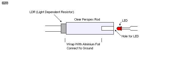
Figure 1 - The Light Pipe Assembly
It will be seen that this is identical to the light pipe used for the bass guitar compressor, except a LED is used instead of a light bulb. We could use a small filament lamp here, but the response is too slow for a protective circuit.
When the light pipe is completed, wrap the LDR end with aluminium foil, and tightly twist a bare wire around the foil to make good contact. Tape the assembly firmly so that nothing comes undone. This acts as a shield, and is connected to the earth (ground) connection on the input connector. Make sure that the foil does not short circuit the LDR leads, or you will get no signal at all. Note that one of the LDR leads will be connected to ground anyway - it does not matter which one.
The complete assembly must be totally shielded from light. I will leave the exact method to the individual constructor, but you might consider heatshrink tubing, a black 35mm film can, or anything else that comes to hand that is light proof. If metal, it must be earthed along with the shield around the light pipe - make sure that the LED leads are well insulated - a short to earth may damage the amp, and will almost certainly do something unpleasant and/ or undesirable.
Figure 2 shows the circuit of the unit. A 10k resistor was selected for the input, and although this is lower than I would like, many power amps have a relatively low input impedance and too much signal would be lost. The LDR simply shunts the signal to earth when it is illuminated. A single unit should control both channels of the power amp as shown. If only one channel is needed, then delete the components for 'Right', including the associated light pipe. Use the input circuit shown in Figure 3 to improve limiting by using a higher input resistance.
An alternative to the light-pipe described here is a Vactrol® (e.g. VTL5C4 or similar, NSL-32SR2-ND [Farnell/ Element14 or Digikey]), or a home-made optoisolator as described in detail in Project 200. However, these do not provide the degree of input to output isolation that you'll get with the light-pipe, so greater care will be needed to ensure that there is no sign of oscillation from the power amp. Because of the relatively high impedances involved, there is a very real chance of feedback. As noted above, oscillation caused by feedback can be very destructive and may be completely inaudible.
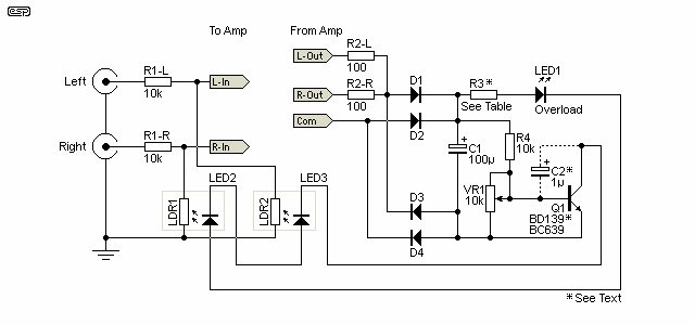
Figure 2 - The Complete Limiter Circuit
The value of R3 must be selected based on the amplifier power. For a 100W amp, a value of 1.8k is about right, but it is likely that a little experimentation will be needed. As a rough guide, the table below will be helpful. The idea is to limit the current through the LED to a sensible maximum. Note that C2 is optional, and will reduce low-frequency distortion but at the expense of speed.
| Amp Power (8 ohms) | Peak Voltage | R3 |
| 20 W | 17 V | 820 R / 0.5 W |
| 50 W | 28 V | 1.5 k / 1 W |
| 100 W | 40 V | 1.8 k / 1 W |
| 200 W | 56 V | 2.7 k / 2 W |
| 500 W | 90V | 4.7 k / 2 W |
Amplifier power in Table 1 is for an 8 Ohm load, and assumes the light-pipe which has a lower sensitivity than a dedicated LED/ LDR optoisolator. All diodes are 1N4004 or similar. The voltage rating for both capacitors should be 63V, and R2-L and R2-R should be rated for at least 1W for any amp over 20W. VR1 should be a multi-turn trimpot. High brightness LEDs will improve sensitivity and are recommended. You may find that you can use different values from those shown, and the circuit is flexible enough to ensure that you'll find a combination that works for you. As noted, the values shown are for a home-made light pipe, but ready-made LED/LDR optoisolators are more sensitive and require far less current. R3 can be increased to suit whatever you are using. It should be possible to use a BC639 if you have a sensitive optoisolator and increase the value of R3.
|
Amplifiers with more than 200W output may require the use of an MJE340 (or similar) transistor to get the voltage rating, which will be too high for a BD139. The caps will also need to be rated at a higher voltage - 100V is recommended. |
LED current is set at a maximum of about 20mA by R3, however this should never be reached for more than a few milliseconds - if that. In most cases, the LED current will be close to zero, and there will only ever be just enough LED current to reduce the LDR resistance sufficiently to lower the amp's input signal to retain the maximum preset power level.
The transistor may need a heatsink, but if so, this will only need to be a simple flag type affair for even the most powerful of amps. Remember to check that the transistor and heatsink are not overheating while you are testing the circuit operation. If you can't keep your finger on the transistor, it is too hot!
The polarity of the connection to the power amp output does not matter (but see the Important Note, above if you have a bridge mode power amp), since a bridge rectifier is used. Very little current is drawn from the power amp output, and the whole circuit is self limiting, so it is not critical. When complete, advance the volume until you figure that this is a loud as you want the amp to be, and adjust the trimpot until the external LED just flashes. Use a multi-turn trimpot, as the setting is quite touchy. It could be made much less so, but at the expense of circuit flexibility.
Now, if you try to drive the amp harder, the external LED shows that the circuit is working, by flashing brighter, but the volume should remain quite stable. This can be checked with an oscilloscope (ideally), but otherwise just set it by ear. As more signal is driven into the amp, it may sound louder, but this is only because the input signal is being compressed.
One of the great benefits of this circuit is that it will be fairly unobtrusive even for hi-fi applications. Since the amplifier should never be driven to the extreme, the circuit will never operate, so nothing is lost. On those occasions when 'someone' winds up the volume too far, then the limiter will do its job, protecting the rest of your precious equipment. You might like to label the external limit indicator LED as 'Overload' or something similar. This will frighten the timid user (others will naturally ignore it completely).
The circuit has been changed to incorporate C2 (which is optional), as I found that with fast LDRs the distortion at low frequencies is excessive. The connection to the base of the transistor was also changed to increase the circuit gain and provide a better limiting action. This includes the reduction of R4 from the original value to 10k. With this arrangement, I was able to set the limiter on a 100W amp to about 80W, and could drive up to 10V RMS into the amp without clipping.
I also found that the resistor power ratings are probably over the top. I used 0.25W resistors, no heatsink and nothing got even slightly warm .... however, I suggest that the power rating on R3 be 1W, since there is a likelihood that with less sensitive LDRs (or standard LEDs) the average power will increase. Drive the amp hard, and make sure the transistor does not get hot. If it does, a heatsink is needed.
The LDR I used is an encapsulated unit with integral high brightness LED (VTL5C4), and is extremely sensitive. These are usually hard to get (they are made in the US by Perkin Elmer - formerly EG&G Vactec) and are not stocked by most suppliers. Unless you need 100 or more, you will have a tough battle! As a result, you will probably be limited to using my light pipe, and this will be less efficient. Note that if the light-pipe is kept fairly short (say 15mm) and a high brightness red or green LED is used, you will probably come fairly close to the VTL5C4 for sensitivity.
The sensitivity of LDRs varies with wavelength, and it's not always easy to get the information so you can decide which colour LED to use. Given the high light output from even rather lowly white LEDs, these are not a bad choice. Some LDRs have their most sensitive region centred around 550nm, which is a green-yellow colour. If you can get enough light without excessive current, most colour LEDs will work just fine. Blue is not a good choice though, as it's at the high frequency end of the spectrum and most LDRs are not very sensitive to blue light. The same applies to infra-red (IR) and ultra-violet (UV) LEDs - they are too far from the optimum colour and won't work well.
For those who don't mind a bit of extra work, you can use an opamp buffer after the circuit to drive the amp's input. This will allow R1 to be a higher value, which will improve the unit's limiting action, but will not reduce the amp's sensitivity. If you decide on this, make R1 (Left and Right) 47k, as shown in Figure 3.
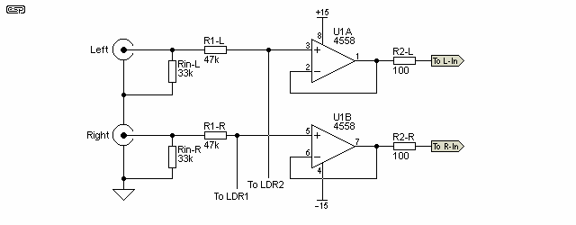
Figure 3 - Using A Buffer To Improve Sensitivity
The opamps can be whatever you want. Since they are acting as buffers only, even the 4558 dual opamp will be quite adequate for PA or mobile disco work. For hi-fi you might want to use something a little better, such as TL072 or NE5532 devices.
|
This circuit cannot protect equipment from distortion caused by an overloaded preamp. I suggest that the gain of the preamp be set so that no sensible input level can cause overload. This might require that you modify the preamp's gain structure to ensure that clipping is not possible. It is vitally important that the (limited) amplifier power is within the maximum continuous power rating of your speakers. As the input level is increased, the average power also increases. A 500W amplifier will cheerfully destroy 500W (peak) speakers, even if the amplifier never clips. Please refer to the article Why Do Tweeters Blow When Amplifiers Distort? for a full explanation. |
 Main Index
Projects Index
Main Index
Projects Index