
|
|
| Elliott Sound Products | Project 86 |
 Please Note: PCBs are available for this project. Click the image for details.
The Miniosc is designed as a pocket sized high performance audio oscillator. Some time after another design was published, it occurred to me that an even simpler, battery operated version was possible and could be made at very low cost as well by using one quad op-amp to provide the entire active circuitry. Employing a nine volt battery supply would put a lower limit on the maximum output level, compared with a mains powered oscillator, meaning that about one volt or so output should still be available.
The mini version of the original Low Distortion Oscillator has been fitted into a pocket sized instrument case including a nine volt battery in its own compartment, and has level and frequency control pots on top with range and mode switches on the sides allowing one handed operation of all controls, a very useful feature.
A mini sized, battery powered sine and square wave source is invaluable for on site testing of all sorts of audio equipment and even workshop use where the item to be tested may not fit on the workbench, for example a 24 channel mixing console or a large powered loudspeaker system.
The oscillator circuit (see Figure 1) involves two unity gain phase shift stages, A1 and A2, in tandem and a gain stage, A3, with back to back diodes and resistor network providing non-linear negative feedback. At a particular frequency (determined by RT and CT - the timing components) A1 and A2 provide 90 degrees phase shift each, 180 degrees in total and the circuit begins oscillating, since A3 and its non linear network has more than unity gain for small signals. As the oscillation level increases the diodes conduct and limit the gain of A3 stabilising the output at the desired level, in this case a little over 1V RMS. However, some distortion of the sine wave peaks is caused by the diodes.
Figure 1 - Basic Oscillator Principle
The principle is quite simple. Using two phase shift networks, the phase is rotated by 180° at one frequency. The final amplifier provides an additional inversion (effectively 180° phase shift), so the circuit will oscillate. The limiter (whether diodes, thermistor or something else) is used to prevent the amplitude from building up to the point where the signal is grossly distorted. Normally, diodes are not at all effective in preventing distortion, but that's where the fourth stage comes into its own.
 |
In the original Wireless World [1] design, a thermistor Philips type, 68k, 20mW was used but you could also use a type R53 or similar if you can get one. Because these are virtually unobtainable anywhere, the current design uses diodes. You may be able to source a suitable NTC thermistor from an old audio oscillator, but even many of these used a PTC thermistor (a small tungsten filament lamp) because the 'real' thermistors have always been expensive and rather fragile. |
The disadvantage of this simple circuit (especially if diodes are used) is that it will be almost impossible to get distortion below around 5% along with reliable oscillation. Even if you can find a suitable thermistor, the distortion will be no better than a typical Wien bridge oscillator, but with more active parts and a restricted frequency range due to the limitations of the opamps.

Figure 2 - Expanded Oscillator Principle With Distortion Cancellation
The fourth stage, A4, is the real secret of the design since it combines the outputs of the three preceding stages using a feedforward* approach. This is done in such a way as to reduce the third and higher odd harmonic distortion products generated in those stages due to the back to back diodes used for level stabilisation. Because the diodes are symmetrical in their effect they cause only third and higher odd harmonics of the sine wave output.
* Note that the term 'feedforward' is not used in the strictly traditional sense here, but refers to the fact that parts of the signal are fed forwards to the final stage. This is more by way of a simple explanation than an attempt to redefine the term (just in case any of the engineering types were planning on taking me to task for my 'misuse' of the word).
The net effect of A4 is to remove at least 90% of these unwanted harmonics from the output over the operating range of the oscillator. The prototype measured only 0.16% THD at 1kHz, somewhat less at lower and more at higher frequencies. At these levels the distortion is barely audible and presents a visually perfect sine wave on an oscilloscope screen. Overall, this represents a much better performance than a typical function generator.
Figure 3 - Complete Schematic of MiniOsc
Referring to the main circuit (Figure 3) there are only two control pots (VR1 and VR2) and two DPDT switches. Of these, only the frequency pot (VR1A/B) is mounted on the PCB. The output level pot can include an on-off switch if you can get one, and will typically be logarithmic ('audio') taper to allow easier setting at low levels. This pot is directly coupled to A4's output to minimise response errors, provided that the load impedance is constant or quite high compared to the output impedance provided by Miniosc (output impedance ranges from almost zero to a maximum of about 1.3k).
Since switched pots may be quite difficult to obtain these days, a separate on/off switch will probably be needed. This should be the same type as the others specified.
The frequency sweep control (VR1A/B, which must be a linear pot) has a range of about 24:1 and in combination with the High-Low range switch having a 18:1 ratio, the audio band is covered (with the exception of the lowest octave) in two overlapping ranges. The possibility of a single sweep of the audio band without the range switch was tried out and later dropped in preference to the present design.
The square/sine wave switch works by disconnecting the negative feedback around A4 allowing the opamp to run 'open loop'. In this condition it is overdriven by the oscillator stage causing its output to saturate at the positive and negative supply voltages producing a squared waveform. The additional four diode network which is switched across the output of A4 and voltage limits the output level in square wave mode to match the sine wave level and at the same time regulates against variations in the battery voltage.
The actual operating level of Miniosc is limited by the use of a single nine volt battery if you choose to power it this way. The discharge curves for various types show a voltage variation of from 9.5 volts down to 6.3 volts is to be expected from 'fresh' to 'flat'. The Miniosc operates as specified over this range with a maximum output level of 1.27 volts RMS sine and 1.45 volts square. The battery drain in sine wave mode is a miniscule 1.7mA increasing to about 4.7mA in square wave mode. This very low drain is mainly the result of using the Texas Instruments TL062 low power dual FET opamp which is ideally suited to the design.
Types like the TL072 and TL082 are not recommended for single 9V battery use due to both the increased battery drain and reduced margin of minimum operating voltage. The TL062 is alone in the 'family', having operation specified down to a plus and minus 3 volt supply. There are other dual op-amps with compatible pinouts that can be used, but verify that they will handle the voltage range of a 9V battery. Any dual opamp can be used if a pair of 9V batteries are provided, or where the oscillator will be powered from a regulated power supply of 12V or more. One dual opamp that cannot be recommended is the LM358 - it will work, but very badly.
Power from the standard 9V 216 style battery feeds a voltage divider (R16 and R17) to provide an artificial centre tap with bypass capacitors and a 1 amp diode to protect the IC from inadvertent reverse connection of the battery. Even a momentary reversal of a good battery would easily destroy the TL062 IC and any of its relatives. Creating balanced plus and minus 4.5 volt supply rails like this allows direct coupling between all the op-amp stages (including the output level control), and also reduces the number of components.
The Miniosc is not a toy oscillator. It is capable of serious work testing domestic or professional audio equipment of all types and will verify normal operation, allow levels to be set, channels to be matched and response curves measured.
Low distortion combined with a particularly high 'envelope stability' of 0.1 dB, even when rapidly swept, is a feature lacking even in many high grade oscillators. Battery operation eliminates the possibility of mains hum in the output and also allows connection to either floating transformer or actively balanced input circuit. Direct coupling of the output circuit eliminates any response errors caused by connecting low load impedances to Miniosc.
Note: The lowest octave of the audio band has been designed deliberately out so as to avoid damaging speakers when using the Miniosc. There are few speaker systems that can safely accept full power input at 20Hz (or 15kHz, so be careful !). The extra low frequency octave is easily added if needed, but it is not appropriate for a portable unit that may be used to drive complete PA systems. The frequency is determined by the usual formula ...
fo = 1 / ( 2π × R × C ) Where R is the resistance (R8/ R9 in series with VR1) and C is capacitance (C1/2 in series or parallel with C5/6)
The square wave function has been included because it is so useful. The rise and fall times are relatively slow, however there is very good waveform symmetry across the audio range.
There are several changes from the original, the most notable being that the frequency pot supports the PCB and is directly mounted. There are still several leads needed though, and assembly will require care and patience.
You may use any case that suits your needs - provided everything will fit of course. Panels should be carefully drilled for the switches, pots and BNC socket to be fitted. The amount of space you have depends on the case you use. The pots will probably need the shafts shortened to allow the knobs to sit flush.
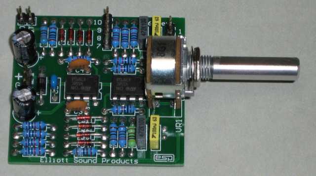
Photo of Completed MiniOsc
The three slide switches fit into slots which are cut with a nibbling tool in the sides of the case and then filed to size. Cut only enough plastic/metal to permit full travel of the actuator. Two small holes will also need to be drilled to mount these switches. Mark their positions using a switch as a template and a sharp point or scriber. Four 2mm x 10mm long mounting screws will also need to be purchased as they are not normally supplied with the switches. It might be possible to find a miniature pot for the level control that includes the DC switch. These are common in small transistor radios, but unless you have one that can be sacrificed you'll almost certainly end up using a small toggle or slide switch.
The PCB may now be loaded. This work should be done carefully to avoid solder bridges and prevent overheating the components. Use a small conical tip soldering iron at a moderate temperature (about 320°C). The all components resistors are mounted normally. Take particular care with the polarity of the diodes and orientation of the ICs. The board is double sided and uses solder resist on both sides, making assembly and soldering easier than might otherwise be the case.
MKT type PC mount capacitors have been specified for the Miniosc as they are now widely available but no other miniature components are needed despite the very small PCB.
Tip: Be wary of 1% metal film resistors with four band colour codes, it is more reliable to measure them with your multimeter than try to decipher the codes.
Wire the battery snap via the on-off contacts on the power switch. It doesn't matter which lead (red or black) goes to the switch but red is traditional. Lastly, glue a small piece of foam plastic in the battery compartment to prevent the battery rattling about.
The BNC output socket has been specified for the simple reason that the mating plug locks in place. An RCA socket was tried at first but proved unsatisfactory since the Miniosc could not be left dangling on its output lead without risk of disconnection followed by the unit going bang on the floor! Using the BNC overcomes this problem and various adapter leads allow conversion to RCA and jack plug when required.
Once assembly is complete, double check all wiring and soldering especially for bridges between tracks or IC pins.
Connect a battery and switch on. If you have an oscilloscope available then a full performance check can be done otherwise simply connect Miniosc to your stereo amplifier and operate all the controls to verify correct operation. The sweep should sound smooth and the pitch should increase as the knob is turned clockwise. A large increase in frequency should be heard when the range switch is operated from Low to High.
The square-sine wave switch should cause a very obvious sharpening of the tone but little increase in the level. The top end of the 'Hi' sweep range should just disappear into inaudibility unless you are much younger than I am!
Warning: Keep the level down for this last test as replacement tweeters can be expensive! High powered tests involving loudspeakers should always be mercifully brief.
Battery drain can be checked with a multimeter and should read around 1.7mA in sine wave mode if all is well and you are using the TL064. Excessive current drain or no oscillation will probably be due to wiring errors, solder bridges or a component or two which has not had one of its leads soldered properly. Depending on opamps used, current drain could be up to about 6mA, and anything below 10mA is most probably perfectly alright if the circuit is working normally.
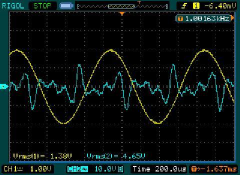
Figure 4 - Waveform & Distortion Residual At 1kHz
The distortion residual above doesn't look wonderful, but the measured THD at the time was only 0.12% - well below audibility for a single tone. The distortion meter insists on providing a nice high-level signal for the residual (which is actually very useful). This is largely immaterial though - the purpose of Figure 3 is to show you the distortion waveform - that means everything that isn't 1kHz, including noise.
Although the Miniosc is not intended to replace the usual bench audio signal generator it can at a pinch do most of the same jobs a bench model does. The fact that the output level remains particularly steady while the frequency is swept rapidly makes response testing a breeze, especially for tape recorders, equalisers, electronic crossovers and loudspeakers too if a flat response sound level meter is available. The overall performance is actually better than many budget test bench audio oscillators, especially at low frequencies. The ability to get less than 0.2% THD at 1Hz or less is generally only possible with expensive test gear. Admittedly, the high frequency performance is not as good as you'd expect from a bench oscillator, but it's still fine for most test procedures.
The main use I foresee for Miniosc is on the spot tests to equipment where little or no other test equipment is to hand. This might mean using your ears as the output instrument, or possibly a VU meter, LED ramp or similar level display built into the unit under test. In many cases a digital or analogue multimeter can be used as an output meter providing that its response is known to be flat over the range to be measured or it has been checked first using your new Miniosc.
Note: Analogue multimeters and VU meters will normally read accurately over the audio band but the same is not true of most digital multimeters where the AC readings taper off above only a few kilohertz.
Slowly turning the sweep control makes pinpointing and tracing rattles and buzzes in speaker systems very simple. Also, you can identify obvious peaks and holes in the response caused by defective drivers or passive crossover networks. Of course, be wary of rattling room heaters or window panes before you condemn the speakers.
The square wave function can be used in conjunction with an oscilloscope to examine transient responses for ringing or more likely when testing by ear when checking out signal processors and effects units like delay and reverberation, whether mechanical or electronic. You need an input signal rich in harmonics for the full sound of these units to be heard. A square wave signal contains all the odd numbered harmonics of a frequency, diminishing in relative intensity, out to beyond audibility.
Sweeping the square wave back and forth over one or two octaves will further enhance the audibility of effects.
A variety of output leads or adapters may be needed. I used a BNC to jack (6.35mm) lead with an adapter to RCA plug when necessary. Lead adapters to XLR plugs may also be made for use with professional type audio equipment. In most cases pins 1 and 3 (or sometimes 1 and 2) should be linked on the XLR connector to connect Miniosc to the input or else connect Miniosc between pins 2 and 3 for floating balanced (transformer) inputs.
Some modifications are possible to the Miniosc circuit as it stands and there may be others you can develop.
The measured performance of the prototype is shown below. These measurements were taken with a TL064 as described in the original version of this project, but will be virtually identical with a pair of TL062 opamps. Measurements on the prototype I built using RC4558 opamps are virtually identical, except distortion was lower (0.13% THD) and supply current higher. The 4558 opamps will work down to about 5.5V (total single supply voltage), but draw a higher supply current. I measured 4.5mA (sinewave output), but this will vary with the opamps because the supply current is not highly specified.
| Frequency: | Low 41 - 1082 Hz |
| High 735 - 18.1 kHz | |
| Output: | 1.27 volts RMS sine (+4dBm) (note 3) |
| 1.45 volts peak square | |
| Load: | 1.0 volts RMS sine into 330 ohms |
| Flatness: | +/- 0.1dB (1%) 41 Hz to 17 kHz |
| Distortion: | 0.16% THD at 1kHz |
| Square wave: | Rise time - 5 us at 10kHz |
| Symmetry - 1% up to 10kHz | |
| Supply: | 6.3 volt minimum |
| Consumption: | 1.7 mA, sine wave |
| 4.7 mA, square wave |
The above is for the oscillator built exactly to the schematic shown, and with frequency setting capacitors and switching as indicated. The PCB version is identical
These figures can be expected to be representative of performance with most opamps designed for audio usage. As noted above, avoid low power opamps such as the LM358, as they are completely unsuitable because they are too slow and have significant distortion.
The original circuit was published in Wireless World, February 1982. The original thermistor was specified as a Philips type, 68k, 20mW (type number 2322 634 32683), however a search indicates that it is no longer available. A reader kindly scanned the article, and a PDF of the 1982 article is available from ESP.
 Main Index
Projects Index Main Index
Projects Index
|