
|
|
| Elliott Sound Products | Linear Power Supply Design - Part 2 |
 Main Index
Articles Index
Main Index
Articles Index
Quite a bit of this article results from recollections of my early foray into designing and making my own transformers for guitar and bass amps (we're talking 50 years ago at the time of writing). I quickly discovered that I couldn't buy off-the-shelf transformers that would provide the voltages I needed or handle the current. One attempt at getting a custom transformer made was both a success and a disaster - it worked, but cost way too much, and was enormous (and very heavy). At that point, I ordered laminations and the best winding wire available (designed for high temperature operation) and proceeded to teach myself transformer design.
Not one of my transformers ever failed, even though it wasn't uncommon for bass players (in particular) to decide to load the amp with far too many speakers. One had 4 × 8Ω quad boxes in parallel (2Ω), on a 200W amp designed for 4Ω. Both the amp and transformer survived this ordeal, but he was told it was a no-no once I found out. 
Initially I used an educated guess to determine the number of primary turns, but later on I became a bit more skilled and was able to come up with a solution that worked very well. It pretty much goes without saying that the transformers used E-I laminations - the best I could get at the time - grain oriented silicon steel (aka GOSS). The windings were enamelled copper, with high temperature insulation. Unlike many enamels available now, the only way to remove the stuff I had is by abrasion - a soldering iron can't get hot enough to damage the insulation!
My transformers were deliberately designed to run the core at a little over the 'recommended' flux density, so idle losses were higher than normal. Because I could use thicker wire (along with fewer turns), they had excellent regulation - far better than anything available at the time. They were also impregnated with (proper) transformer varnish, and baked at around 100°C until tender they were incapable of any internal wire movement. The ratings of the ones I built ranged from around 150VA up to 500VA. They were close to indestructible in service.
Many years later I had some transformers made (of which I still have a couple), and requested the same thing - run the core 'hot', with higher than normal magnetising current. Interestingly, the design engineer at the place that made them for me commented that "I wish more people thought that way." At idle, they dissipate around 40-50W, and actually run slightly cooler when driven to around ½ power than with no load. The supply voltages don't collapse as badly as 'store-bought' transformers, due to lower winding resistances. These are shown in the tables below, indicated by  .
.
As regular readers may have noticed, I like transformers, and I'd like others to appreciate them as well. Using transformers is one thing, but understanding them is better. They are extremely efficient, and when designed specifically for a task you can take comfort in the knowledge that the transformer should outlive the equipment, and may even outlive the designer/ builder. It's only when the wrong transformer is specified for a job that you'll have problems, although both power and output transformers for valve (vacuum tubes) have a harder life due to the high voltages that are required. That's another story altogether, and is not covered here.
Part 1 of the 'Linear Power Supply Design' articles is (I freely admit) somewhat mind-numbing, especially for a beginner. This probably should be 'Part 1', but it can't be because that already exists (and has done so since 2001). There's not much in that article that isn't shown here, but this is deliberately simplified (some may disagree) to provide the information you need to get started. Many sites show the basic design process, but most (by a huge majority) leave out all the things that cause problems for many DIY hobbyists, and even some professionals. The most common omission is to not mention the transformer's winding resistance and how it affects performance.
This is more serious than it sounds at first, because there is only one reason that transformers are available in multiple different power ratings (actually VA - volts × amps). If a room-temperature superconducting material could be found for the windings, the only variable would be the output voltage. The only difference between a 30V, 10VA and a 30V, 1,000VA transformer is the thickness of the wire used for the primary and secondary. A larger core is necessary for higher output current so that the heavier-gauge windings will physically fit into the core. If the windings were superconductors, the wire size constraint would be (at least partly) eliminated.
Unfortunately, room-temperature superconductors are only a dream at present. This means that we can't escape from the fact that high power transformers must be far larger and heavier than low power types, so the winding resistance can be minimised. Any resistance in the circuit causes losses, and losses generate heat. If 1A flows through a resistance of 1Ω, 1W is lost as heat. Increase the resistance to 10Ω and that becomes 10W. Increase the current to 2A (still with 10Ω) and you now lose 40W, since power is determined by the square of current. While this is simplistic, it remains the biggest challenge to making high current transformers with low losses.
Contrary to what you might imagine, the maximum flux density in a transformer core occurs with no load. This is covered in detail in the Transformers article, but it's mentioned again here because it's important to understand it. If you assume the 'alternate possibility', your understanding of transformer functions will lead to assumptions that are seriously at odds with reality.
There are sections in this article that explain all of the things you'll come across, but with more detail than is normally provided. While it's certainly interesting, much of it isn't relevant to building a simple power supply. It's relevant to the transformer designer, but once you've bought the transformer you're stuck with what you have. However, this isn't entirely true if the transformer is a toroidal type, as it's a relatively simple matter to add some extra turns to get a bit more output voltage if you need it.
Transformers are commonly described as being inductive components, but this is a gross simplification of reality. An unloaded transformer is certainly inductive, but the current drawn by the inductive component is small because the inductance is so high (typically at least 10 Henrys for a 230V, 50Hz transformer). When powering a resistive load passing more than 10% of the rated output current, the inductance can be ignored as it's (close to) irrelevant. Few people seem to understand this, including those who should be aware.
For anyone who would like to run transformer power supply simulations, I suggest you read the article Power Supply Simulation (Not As Easy As It Looks), which covers the tricks you can use to make a simulator emulate the 'real world' performance of transformers and rectifiers. The info in that article isn't just for simulations though, as it's relevant in what's laughingly known as the 'real world'. 
It's important to understand that the so-called 'linear' power supply is not linear at all. Current is delivered from the transformer (and the mains) only when the secondary AC peak voltage is greater than the stored charge in the filter capacitors. The current waveform is highly non-linear (distorted) and it can inject noise into any wiring that's close by (including speaker cables!). This means that the supply has a poor power factor, but that is not covered here. It's important (to the power company) but you have little or no control over it. You pay for power (watts), but not VA. The transformer is affected by VA, not watts.
Transformer primary (mains) and secondary wiring should be kept well separated from all signal and speaker wiring. The 'ground' point must always be taken from the centre-tap of the filter capacitors for a dual supply to prevent diode switching noise from being injected into the ground wiring. Never take the ground from the transformer centre-tap or from a bridge rectifier, even if there's only a few millimetres of wire between that and the filter caps.
Wire has resistance. When you have to use 800 turns of wire for the primary, the only way to reduce the resistance is to use a heavier gauge wire, but that may not fit into the winding 'window'. Like almost everything, transformer design is a compromise. A skilled designer will get the best result possible from the least amount of material (steel and copper), with most design now being done by dedicated software.
Transformers are limited by temperature, and the temperature is determined by the power dissipated in the windings. This is known as 'temperature rise', which means that at full load, the temperature will rise by (for example) 40°C above ambient. The ambient temperature is not the temperature in the room, outside or anywhere else that is not the immediate surroundings of the transformer. A transformer in a sealed enclosure will increase the temperature within that enclosure, and that is the 'ambient temperature'! The eventual temperature of any transformer is determined by winding resistance, the load on the secondary, and ventilation. Any transformer can be given a higher VA rating just by using a fan, a technique exploited in microwave ovens.
The maximum allowable temperature is determined by the insulation temperature rating. It's uncommon for most suppliers to specify the insulation class, but expect most transformers to be rated for no more than 120°C. Many smaller transformers (up to 100VA in some cases) have an internal thermal fuse. It's not accessible as it's buried inside the primary winding, and if it opens the transformer must be discarded as it's usually impossible to replace it. 120°C is very hot, and you'd normally expect a transformer to run at no more than 60-80°C, with lower temperatures being very much preferred. As noted, you can use a fan to minimise the temperature rise, but that's rarely necessary in most power supplies.
| IEC 60085 | NEMA/UL | Temperature | Materials |
| 105 | A | 105°C | Organic materials such as cotton, silk, paper, some synthetic fibres |
| 120 | E | 120°C | Polyurethane, epoxy resins, PET/ Mylar®/ Polyester |
| 130 | B | 130°C | Inorganic materials e.g. mica, glass fibres, with high-temp binders |
| 155 | F | 155°C | Class 130 materials with binders stable at higher temperatures |
Transformer secondary voltages are nearly always specified at full rated current into a resistive load. This takes the winding resistance into consideration, and it invariably means that the output voltage with no load will be higher than the quoted secondary voltage. For example, a 100VA transformer is designed for an output of 30V RMS at 3.33A. When loaded with 9Ω, the secondary voltage will measure 30V RMS (if the actual mains voltage is the same as the rated primary voltage!), but when unloaded (no secondary current) the voltage will be around 33.5V RMS, giving a DC voltage of about 45V (including diode losses for a bridge rectifier). With a resistive load, the regulation is around 11.5% (compare this with the values shown in Table 4.1). When loaded with a bridge rectifier and filter caps followed by a load that takes the transformer to full load (24Ω for 100VA) the DC voltage falls from 46V to 38V - a regulation of about 17%. This is completely normal, and it happens with all transformers.
As a result, all linear power supplies will provide more than the expected voltage with no (or light) load, and less than expected at full load. Failure to appreciate this is common, largely because most articles that describe linear power supplies either don't mention it, or it's glossed over expecting that "Everyone knows this". In reality, everyone does not know this, other than from their own measurements, which may (or may not) be sufficiently accurate. 'Knowing' something is very different from observing a phenomenon, but not understanding how or why it happens.
Mains voltages are nominally 230V or 120V, but the actual voltage varies from hour to hour (and sometimes minute to minute). The tolerance is generally ±10%, but it's very common for that to be exceeded. Australian mains voltage is nominally 230V, but it's not at all uncommon to see up to 260V (+13%) and sometimes more (I've measured up to 265V RMS occasionally). Much the same occurs everywhere, and in some places the claimed 'accuracy' can be well over ±10%. If the input (primary) voltage changes, so too does the secondary voltage, and in direct proportion. That's only one of the many reasons that your DC voltages are different from the theoretical values.
Of the variables, winding resistance is easy, but only if the transformer remains at the same temperature as when measurements were taken. Copper has a thermal coefficient of resistance of (about) 0.395%/°C (more commonly stated as 4E-3), so as it gets hot, the resistance increases. This increases losses, causing it to get hotter. Provided it's used within its (long term) ratings, self destruction won't occur. Any transformer can be heavily overloaded for a short time, and no damage will occur if it has time to cool again. For example, a 100% overload for 30 seconds has to be compensated by zero load for 30 seconds (50% duty cycle). You can use the temperature coefficient to calculate the winding temperature if you wanted to go that far.
RT2 = RT1 × ( 1 + α × ( T2 - T1 )) For example ...
RT2 = 6 × ( 1 + 3.95E-3 × 50 ) = 7.185Ω for a temperature rise of 50°C
Where T1 is the initial temperature, T2 is the final temperature, and α is the thermal coefficient of resistance. I don't expect anyone to bother, because it's far easier to just feel the transformer with your hand (all live connections must be properly insulated!). If it feels hot, then it may be under-rated for the application. The same technique is regularly used by experienced technicians to test heatsink temperatures. The 50°C temperature rise shown above would have the transformer operating at 75°C if the ambient temperature is 25°C. That's much hotter than I'd want to operate a transformer on a continuous basis!
The following table shows measured values from three transformers I tested. All were tested with 230V input, and the output current shown is across the full winding. Some transformers have separate windings that can be paralleled for double the current, but at half the total voltage. Foe example, a 25+25V transformer can output (say) 6A at 50V (300VA) or 12A at 25V (also 300VA). The last transformer marked with () is a custom design to my specification).
| Type | VA | Volts (nominal) | Amps | Pri | Sec 1 | Sec 2 |
| Toroidal | 230 | 25+25 | 4.6 | 6.45 Ω | 237 mΩ | 238 mΩ |
| Toroidal | 300 | 25+25 | 6.0 | 4.21 Ω | 159 mΩ | 163 mΩ |
| E-I | 212 | 28+28 | 3.8 | 10.25 Ω | 392 mΩ | 397 mΩ |
| E-I () | 350 | 28.5+28.5 | 6.1 | 6.19 Ω | 225 mΩ | 241 mΩ |
The primary is designed to dissipate less is because it's internal, surrounded by the secondary. It gets less cooling, so reducing its heat output is good engineering. You can do the calculations for all three transformers listed above and see the same thing. While this is somewhat peripheral to the main discussion, it's interesting and worth knowing about. You may also be curious why the secondary winding resistances are different. The secondary is wound in layers, so the outer layer has a slightly greater length of wire for the same number of turns as the inner layer. Almost all transformers will have the same (small) difference in secondary winding resistances. An exception is when the secondaries are bifilar wound, with both windings applied at the same time. This cannot be done with high-voltage transformers, as there isn't enough insulation to ensure there can be no voltage 'break-over' between windings when they are connected in series.
For the 300VA toroidal transformer, the primary will dissipate just over 7 watts at full load, and the secondary will dissipate 11.6 watts. With a resistive load, the effective input voltage is reduced by 5.4V from the nominal 230V (224V RMS) due to the voltage drop across the winding resistance. This reduces the total flux density in the core. With a total secondary resistance of 322mΩ, at full load (6 amps) the voltage drop is 1.92 volts. When the transformer is designed, the turns ratio is adjusted to compensate for these losses, so at no load the output voltage will be more than 50V. For 230V to 50V, the ratio is 4.6:1, but the transformer will be wound with a ratio of around 4.3:1 and that will give a no-load output voltage of 53.5V.
You don't need to understand this to build a power supply, but if you're designing one it helps. Most people just buy the suggested transformer and it usually works out just fine, but there's a great deal to be said for fully understanding why the voltages you measure aren't the same as you expected. Since a great deal of the ESP site is intended to show electronics enthusiasts just how things work (and why), I feel that it really is important to understand the nuances that are usually missed.
The same three transformers were also tested for no-load input current (aka magnetising current - Imag) and unloaded secondary voltage across both windings. The input was set for 230V RMS for each test. The four sets of data below are measured values, not the nominal values claimed on the nameplate. The rated values will be achieved only with a fully resistive load, and not with the usual rectifier and filter capacitor power supply that will be used in almost every case.
| Type | VA | Imag | Idle Loss, VA / W | Vout (AC) | Regulation | Output (DC) |
| Toroidal | 230 | 19.2 mA | 4.41 VA / 1.16 W | 53.3 V | 6.6 % | ±36.75 V |
| Toroidal | 300 | 16.0 mA | 3.68 VA / 1.93 W | 53.2 V | 6.4 % | ±36.65 V |
| E-I | 212 | 66 mA | 15.18 VA / 10.8 W | 60.0 V | 7.14 % | ±41.46 V |
| E-I () | 350 | 152 mA | 34.96 VA / 7.32 W | 60.7 V | 6.5 % | ±40.64 V |
The idle loss was measured in VA and watts, and while marginally interesting it's not actually very useful unless the transformer is powered on 24/7 and you want to know how much it costs to run. While you might expect it to be determined by I²R, that's not the case at all. The losses are a combination of copper loss and 'iron loss' (losses in the core). What is slightly interesting is the ESP transformer, which has lower power loss (as opposed to VA) than the other E-I transformer. I double-checked this, and it's correct. Part of the reason is the higher primary resistance, but it shows that the core losses are greater too. This is likely due to 'budget' steel having been used. All normal transformer measurements result in VA, which is the only rating that counts. In terms of no-load operating cost, there's no contest as the toroidal transformers win hands down.
The comparison between the 212VA E-I transformer and the two toroidal transformers shows that the difference isn't as great as expected. The latter have lower magnetising current and better regulation than the E-I type, but in use the difference will be minor. All of the figures shown for these transformers are very accurate, but the normal ±10% mains variation is not considered. This makes accuracy a moot point, but it's still instructive (if not very useful) to be able to take these measurements. Doing so shows the processes involved, but in reality you can dispense with this in its entirety. The ESP transformer is one I had made to my specifications, and its regulation is almost as good as the 300VA toroidal. This comes at a price though; much higher no-load losses. When these were made (ca. early 1980s), toroidal transformers were rare and very expensive.
A final piece of trivia that can be useful (sometimes) is the number of turns per volt (TPV). All transformers require sufficient turns to keep the magnetising current low enough to prevent core saturation. This is based on the size of the core and the maximum allowable flux density. For silicon steel, the maximum flux density is generally 1 Tesla (65,000 lines per inch²), but it can be pushed a little higher if you are willing to accept higher no-load losses. For the three transformers, I measured the following TPV ...
230 VA Toroidal: 3.89
300 VA Toroidal: 3.45
212 VA E-I: 2.72
350 VA E-I: 1.91
It's obvious that both of the E-I transformers have fewer turns per volt than the 'optimum', and this is the reason for the higher no-load losses. The two toroidal transformers have more turns per volt (hence lower losses), but quite obviously use thicker wire as the resistance is lower. It's easy to work out how many turns are required for any given voltage. For example, with (say) 3.5 TPV, a 230V primary needs 805 turns. There is a big difference between toroidal and E-I transformer cores. The toroidal core has no air-gap, and the onset of saturation is much more rapid. An E-I core can be pushed a little harder, because the junction between E and I laminations introduces a small air gap that makes saturation a little less radical. Higher flux levels can be tolerated, and it becomes a trade-off between no-load and full-load losses.
Note: The turns/ volt of a 50Hz transformer is always greater than an equivalent transformer designed to operate at 60Hz A transformer for 50Hz needs 1.2 × the number of turns for the same transformer at 60Hz. It used to be common for 60Hz-only transformers to be used in US made equipment, but global trade means that most (but not all) US (or Canadian) transformers are now made to work with 50-60Hz, and 120-240V mains. A 60Hz transformer will overheat (often to the point of failure) when used at 50Hz, even if a step-down transformer is used to reduce 230V to 120V. A transformer designed for 50Hz will work perfectly with 60Hz, and no precautions are needed.
To measure TPV, simply wind one turn around the outside of the existing windings, apply the rated voltage to the primary, then measure the voltage (in millivolts). For the 300VA toroidal transformer, I measured 290mV for one turn, and TPV is simply the reciprocal (1/V). This works out to be 3.4482 (3.45 TPV is close enough). It's more accurate if you add 10 turns, and divide the measured voltage by 10. You don't need to know this unless you are adding a new winding to an existing transformer (something that can be useful). For example, if you need an auxiliary 15V AC supply, you'd just add 60 turns evenly spaced over the existing windings, using enamelled copper wire thick enough to handle the current. That will give you an unloaded voltage of 17.4 volts. Wrap the additional winding with tape for protection. Do not use ordinary electrical tape!
| VA | Reg % | RpΩ - 230V | RpΩ - 120V | Diameter | Height | Mass (kg) |
| 15 | 18 | 195 - 228 | 53 - 62 | 60 | 31 | 0.30 |
| 30 | 16 | 89 - 105 | 24 - 28 | 70 | 32 | 0.46 |
| 50 | 14 | 48 - 57 | 13 - 15 | 80 | 33 | 0.65 |
| 80 | 13 | 29 - 34 | 7.8 - 9.2 | 93 | 38 | 0.90 |
| 120 | 10 | 15 - 18 | 4.3 - 5.0 | 98 | 46 | 1.20 |
| 160 | 9 | 10 - 13 | 2.9 - 3.4 | 105 | 42 | 1.50 |
| 225 | 8 | 6.9 - 8.1 | 1.9 - 2.2 | 112 | 47 | 1.90 |
| 300 | 7 | 4.6 - 5.4 | 1.3 - 1.5 | 115 | 58 | 2.25 |
| 500 | 6 | 2.4 - 2.8 | 0.65 - 0.77 | 136 | 60 | 3.50 |
| 625 | 5 | 1.6 - 1.9 | 0.44 - 0.52 | 142 | 68 | 4.30 |
| 800 | 5 | 1.3 - 1.5 | 0.35 - 0.41 | 162 | 60 | 5.10 |
| 1000 | 5 | 1.0 - 1.2 | 0.28 - 0.33 | 165 | 70 | 6.50 |
The above table appears in several ESP articles regarding transformers, and is shown again here because it's so useful. The two toroidal transformers I tested have slightly different regulation from that shown in Table 1.4, but the difference is not significant. There are many other factors that influence the output voltage you measure, particularly when it's rectified and filtered. These are covered next, and while you can't change anything, at least you will know why the voltage is different from the assumed value.
Another term you'll find in any text about transformers is the turns ratio. This is simply the ratio of input to output voltage, so a transformer with a turns ratio of 4.32:1 means that for every 4.32V on the primary, there will be 1V at the secondary. With 230V input, the output is 53.24V (as shown tor the 300VA toroidal transformer in Table 1.3). Although it's not relevant for mains transformers, the impedance ratio is the square of the turns ratio (18.66:1 for the same transformer).
You can use the impedance ratio to consolidate the effective winding resistance of both primary and secondary. For example, if the turns ratio is 10:1 (230V input, 23V output) and the primary resistance is 10 ohms, the effective primary resistance is 10Ω / 10² = 0.1Ω (100mΩ). This can be added to the actual secondary resistance to obtain the total. If the secondary resistance is (for example) 250mΩ the total effective series resistance is 350mΩ. I don't expect many readers will take it to this extreme, but it sometimes comes in handy - particularly for simulations and/or detailed analysis.
We expect a sinewave from the mains, but it not - it's invariably distorted. The degree of distortion varies throughout the day, and depends on the current loading on the grid. It's fair to say that the 'rules of thumb' that we all use are either wrong, or at least inaccurate. Surprisingly perhaps (perhaps???), this doesn't matter very much, because the errors created by the basic formulae are smaller than the errors caused by mains variations. So, you can continue to use √2 (and its inverse) and not worry about it. Provided you understand that the results are (very) approximate, then you're well on your way to understanding linear power supplies.
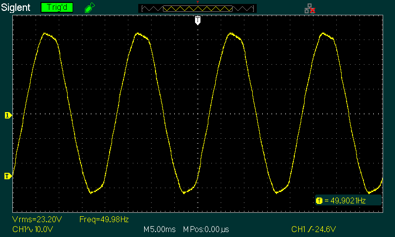
Figure 2.1 - Distorted Mains Waveform
The above is a capture from the mains (via a transformer for safety), showing obvious distortion. We'd expect the peak voltage to be ±32.5V for a 23V RMS sinewave, but the oscilloscope shows ±32V (1V peak-peak lower than expected). The voltage was exactly 23.0V RMS, measured separately with a precision bench multimeter. This is normal, so it's obvious that a small voltage has been 'lost' from the mains. In itself, this is a minor contribution to the inaccuracies you'll measure when testing a power supply. The transformer used to drop the mains to a safe value was operated well below saturation to ensure it didn't contribute to the mains distortion.
However, it is important that you recognise that the mains waveform is distorted, as that reduces the actual (as opposed to calculated) DC voltage. The waveform at the transformer's secondary is also distorted (in much the same way as the mains), because the capacitor peak charging current is much higher than the RMS value. As a general rule, expect the AC RMS current to be at least 1.8 × the DC current. It can be greater than this, and in general I prefer to use a 2:1 ratio as that's usually more realistic.
The simple relationship we use to convert AC (RMS) to DC (AC × √2 [1.414]) doesn't work when the waveform is distorted, but it's still perfectly alright to keep using it. At low currents the error is so small that it doesn't matter. At high current, it doesn't work at all, due to the winding resistances described in the previous section. These can be sufficiently high as to make the average DC voltage almost the same as the RMS voltage when high current is drawn form the supply.
The 300VA toroidal transformer will provide a DC voltage of 69.5V with a (roughly) 1A load and 10,000µF filter cap, and supplied with a 230V sinewave. That is reduced to 66.7V DC under the same conditions, but a 230V RMS distorted (about 4.4% THD) waveform. The additional distortion created by the transformer's winding resistance reduces the voltage even further.
First, we select a transformer. Because I already had a simulation file using the ESP custom transformer, that's the one I used for the example. Any will work of course, and the results are very good if all the information is supplied. The details are shown on the schematic, with voltage and current under load (about 310VA). The primary winding will dissipate 12.7W, with the first secondary (225mΩ) dissipating 6.84W and the second (241mΩ) 7.33W (a total secondary dissipation of 14.17W). The whole transformer dissipates 26.87W when providing 206W DC. Note that this does not include magnetising current, and this is reduced under load due to the primary resistance. The effective RMS input to the primary is 223V RMS for a 230V RMS input under the load conditions shown below.
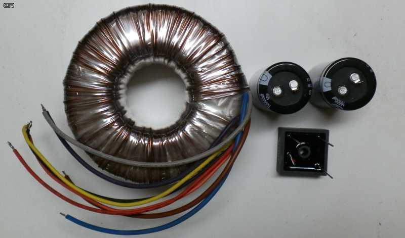
Figure 3.1 - Power Supply Components
The above shows the total parts needed for a 'typical' power supply. The transformer is 230VA (but only because it was the first to hand to add to the photo), with 25+25V secondaries. The two filter caps are 10,000µF, and the bridge is a chassis mount 25A type. Compare this with Fig. 13.4 (a 60W switchmode supply) in terms of complexity and the number of parts needed. The transformer shown will be more than sufficient for a pair of 100W (4Ω) amplifiers for hi-fi usage. You could get more, but the voltage is limited (±35V DC). The wiring is simplicity itself, apart from the mains input and switch which must be properly installed to prevent accidental contact.
Normally, transformer selection doesn't concern us if the transformer is specified as part of an overall design, but when it's necessary to specify the transformer yourself, then without guidelines you are in the dark. You don't need to go into as much detail as I've done here, but this example gives you a much better idea of what you can (and cannot) get away with. Most loads are not continuous, so 'transient' transformer overload is not an issue. If the load current is continuous, then you need to perform detailed tests to ensure that the transformer will survive, and to ensure that you get the voltage(s) your circuit needs.

Figure 3.2 - Power Supply Schematic
The expectation is that the DC output voltage will be around 79.6V, but it's not, it's 70.3V. The secondary waveform is badly distorted because of the high-current pulses needed to recharge the filter cap and supply the load current at the same time. The peak current is 12.8A, with the RMS value being 5.51A, and a DC load current of 2.93A. That means that the AC current is almost 1.9 times the DC current! The 'rule of thumb' is that the AC current is 1.8 times the DC current, but as you can see that's not necessarily the case. It does become closer to 1.8 with transformers having higher winding resistance.
Figure 3.3 - Voltage & Current Waveforms
For the simulation above and those that follow, I used a 'pure' sinewave for the input, because the normally distorted mains waveform changes things and makes analysis harder. As a result, you will not measure the exact relationships shown, but the results will still be well within normal tolerances. Above we see the voltage and current waveforms. As noted above, the transformer's secondary current is 5.51A RMS, with peaks of 12.8A. The peak to RMS ratio is 2.323:1, and the diode conduction period is about 3.4ms for each half-cycle. The diodes only conduct when the incoming AC is greater than the capacitor voltage. The average DC voltage (blue waveform) is 70.73V, ripple voltage is 1.9V RMS or 6.14V peak to peak (8.7% based on p-p or 2.7% based on RMS). Note that you can't use the √2 multiplier to covert RMS to peak-peak because the waveform is not a sinewave.
You can see that once the peak AC is higher than the DC level (by ~0.9V) the DC voltage follows the AC waveform. The two are in almost 'perfect harmony' as the filter capacitor charges. The only difference is the diode forward voltage drop, which varies with current (the forward voltage of most diodes is up to 1.2V at maximum current). This distorted waveform is also passed back into the mains supply via the transformer, and is not mitigated by the primary resistance.
The waveform distortion is a direct result of winding resistance and peak current. With the primary resistance of 6.91Ω and current peaking at 3.4A, that takes 23.5V from each mains peak (positive and negative), so the effective mains voltage is only 301V peak, not 325V peak as expected. Interestingly, the voltage across the primary (after Rp) is 223V RMS, due to the distorted waveform (flux density is determined by the peak voltage, not RMS). On the secondary side, there's a total of 446mΩ with peak current of 12.95A, a further 5.98V (peak) is lost, and that's why the regulation is so poor. This affects all transformer, bridge and filter cap combinations in the same way. The only way to reduce these losses is to use a bigger transformer.
The ripple voltage can be reduced by increasing the value of C1. Doubling C1 (6,6000µF) halves the ripple voltage, but increases the transformer's secondary RMS current to 5.54A. Although there is a myth circulating that using a much larger than normal filter cap will 'burn out' the transformer, it's complete nonsense. You can use as much capacitance as you like (or can afford) without concern. The increase is small, and it gets even smaller once the capacitance exceeds 10,000µF (10mF).
You may (or may not) have noticed that the loaded (310VA) power dissipation is less than that at no load. I can't simulate core saturation easily (and it's inaccurate when attempted), but from experience I know that the transformer used for these simulations runs a little cooler under moderate load than at idle. Although I estimated the VA rating to be 350VA, based on the internal dissipation figures shown above it could be pushed to 400VA if the regulation isn't a concern. Would I run it at more than 350VA with a continuous load? "No" is both the short and long answer.
Something else that you may (or may not) notice is that the 'clipped' AC waveform has peaks that rise in voltage in Figure 3.2, but the mains waveform shown in Figure 2.1 shows the peak voltage falling at the peaks. The reasons for this don't appear to be discussed anywhere. I suspect that it's simply due to phase shift through the power distribution network, caused by a combination of partially inductive loads and power-factor correction capacitors on the network. In some mains waveform captures you may find on the Net, the mains is either 'flat-topped' or shows the voltage rising slightly, so it's location dependent. The waveform I captured shows the mains distortion that existed at my location at that time of day. It does change, and I've seen different waveforms during other tests.
The constant current drain of a Class-A amp means that you must design the supply for continuous (rather than transient) current. Other amplifiers (notably Class-AB and Class-D) draw a widely varying current, depending on the load and instantaneous output power. This is catered for in all ESP designs, but it still means that the continuous output power is a little less than you might expect with some loudspeaker loads. Transformers are always specified that will cater for continuous high power, and that means that they are usually larger than may be suggested for other designs you may come across.
When a power supply is used with an amplifier, the basic things we need to know before starting are as follows ...
Power output and minimum impedance, or ...
Peak and average DC current
Acceptable power supply ripple voltage
With only these criteria, it is possible to design a suitable supply for almost any amplifier (or power supply for other applications). I shall not be describing high current regulators or capacitance multipliers in this article - only the basic elements of the supply itself. These other devices are complete designs in themselves, and rely on the rectifier/ filter combination to provide them with DC of suitable voltage and current.
By knowing the average DC current and voltage, you can work out a rough approximation of the transformer VA rating needed. For example, a 100W (4Ω) amp will use ±35V DC supplies, and draw a peak current of up to 8.5A with a 4Ω load. The speaker current is about 6.2A RMS, and the average DC supply current is 2.6A (close enough) for each supply. Since the supplies are in series, the current in each is the same - 2.6A. However, this is the peak current for a continuous sinewave, and the average is less. We'll assume a peak-to-average ratio of 10dB (10W average at the onset of peak clipping), as this is likely to be the worst case. The average DC current is only about 720mA. Because of the rectifier conversion, the AC current will be 2½ times that, or about 1.8A.
The transformer needed for a single 100W, 4Ω amp with ±35V is 25-0-25V, or 50V in total. 50V with 1.8A is 90VA (180VA for stereo). If you think that can't be right, you would be correct - it's actually less. It's uncommon for any home system to be operated at full power for any length of time. Even professional audio is subject to the same level variations that is a characteristic of music, although they are nearly always pushed closer to their limits. Note that this usually does not apply to guitar amps, which are often driven well into clipping much of the time.
Figure 4.1 - Dual Primaries For 120/ 230V Operation
In many cases, transformers are supplied with dual primaries. This allows them to be used with 120V (60Hz) and (nominally) 230V (50Hz). However, twice 120V doesn't add up to 230V, it's 240V. This is a 4% error, so when used with 230V the secondary voltage(s) will be 4% low, compared to the voltage provided with 120V mains. There's nothing (sensible) you can do about the error, and the difference is not worth worrying about. The mains voltage will vary by more than that during the day. The important part to be careful with is the polarity of the windings. If you get the polarity of one wrong, the result will be a splattered fuse, because the transformer places a very low resistance across the mains. Some transformers provide the details on the label, and others just provide the wire colours for each primary. When described this way, the colours are (almost) always in order (start - finish). The transformer shown in Fig. 4.1 shows the primaries as BRN-VIO+GRY-BLU, and the secondaries as RED-BLK+YEL-ORG. The first colour in each 'group' is the start (indicated by a dot in schematics). Note that there is no convention for colour-coding, and it varies by manufacturer.
Due to the highly variable nature of music, it's very difficult to determine the 'true' average current drawn. It's always better to over-estimate than under-estimate, although that does mean you spend a bit more for the transformer. That comes with another benefit too - the supply rails don't vary by much as the amplifier is used. When dealing with a Class-AB amp, a reasonable assumption is to use a transformer rated for roughly the same VA as the output in watts. A stereo 100W per channel amp will be perfectly happy with a 200VA transformer. Some texts suggest 0.7, meaning that the transformer only needs to be 140VA. For normal home listening, this is usually more than acceptable. You won't be able to get the full power with a sinewave, but few of us listen to high power sinewaves for pleasure.
If you use a transformer that's less than the amp power, it may be overloaded with continuous high level programme material, but music is dynamic and the average power is lower than you think. A 100W amp pushed to mild clipping will normally have an average power of less than 10W. Of course, that depends on the type of music and the peak to RMS ratio of the signal. If you subscribe to the idea of using the minimum you can get away with, even a 100VA transformer for a stereo 100W amplifier will be perfectly alright with normal programme material, but you won't get the full rated power except with transients.
The peak to RMS ratio of music is highly variable. FM broadcasts are usually compressed, and they represent the worst case, so that's what I measured. Over the period I monitored it, the peaks were at ±2V and the averaged RMS (taken over a large number of samples) was 507mV, a 'typical' ratio of 4:1 (near enough) or 12dB. That means that a 100W amplifier driven just to the onset of clipping will be delivering an average power of 7.2W (12dB below 100W). The RMS speaker current is therefore about 1.3A into 4Ω. When the ESP designed transformer is powering a pair of amplifiers delivering maximum output with programme material, the transformer is operating at less than 200VA for a stereo pair. Of course, this assumes that there are no breaks in the music, and the amp is constantly driven to the verge of clipping. In normal use this is unlikely! Just 7.2W into 90dB/W/m speakers means 98.6dB SPL at one meter (and one speaker). At the listening position with stereo, it won't be much less.
For those who prefer a simple answer with the minimum of explanation, this summary should be ideal. Naturally, you don't have all the information - just enough to make a reasonably sensible selection.
The 'fudge-factor' of 0.7 is a good overall compromise, and it's rare that this will cause any issues. A dual (e.g. 100W/ Channel) amplifier needs a 140VA transformer, so you'd select the closest available. With toroidal transformers, the most common in this range is 160VA, with is perfectly acceptable. If the transformer is larger you get 'stiffer' supplies with less voltage 'sag' during transients. However, while the difference is easily measured, it will almost certainly be inaudible. As noted above, you cannot use this formula with guitar amps - the VA rating should not be less than the amplifier power. A 100W guitar amp therefore needs a minimum transformer rating of 100VA, and preferably a bit more. I wouldn't be happy with less than ~150VA for a 100W guitar amp.
In the following, the transformer has dual secondaries, connected in series for most, but kept separate for Fig. 5.3 and paralleled for Fig 5.4. There are a few transformers available that have a 'true' centre-tap, but they are now fairly uncommon - particularly for toroidal transformers. There is no difference whatsoever between a true centre-tap and one made by joining the two windings. When connecting the windings in series, they must be in-phase, with the start of the second winding connected to the finish of the first. Most toroidal transformers have a diagram that shows the colours used, and they are in order - start-finish.
Note: If you use a muting system that relies on an AC connection to provide a power-off mute (such as Project 33), there is only one connection that works properly with a 'stacked' supply (Fig. 5.3). The take-off point is shown on the drawings that follow, and can be ignored if it isn't used.
There is only one rectifier type that will be covered in depth - the bridge (single or dual supply). The so-called single-supply full-wave rectifier is a throwback to the valve era, when it was difficult to use any other topology with valve rectifier diodes. It was possible to make a bridge rectifier using valves, but the extra filament windings and multiple valve diodes made it far too expensive to consider. Due to poor transformer utilisation, it will be discussed only in passing. Note that in each case shown, the 'ground' of common point is as close as possible to the centre-tap of the filter capacitors, or for two (or more) sets of caps, from the last set.
Half-wave rectifiers are an abomination, and even with only a few milliamps they can cause core saturation with a toroidal transformer. I don't recommend them for anything unless there is no other choice (which is very rare indeed). In most cases, anywhere a half-wave rectifier is used, you can (and should) use a bridge. The one exception is with some valve amplifiers, where a separate tap on the HV winding is used for the negative bias. You cannot use a bridge rectifier for that, but the current is very low (the only saving grace). Because of the likelihood of core saturation, I will provide no analysis of a half-wave rectifier.

Figure 5.1 - Dual (Positive And Negative) Power Supply Schematic
Figure 5.1 shows the most common transformer power supply used today. The transformer is the same one used in Figure 3.1, but the centre-tap is now connected and there are two filter capacitors in series, with twice the capacitance for each. The secondary currents are different because the two secondaries have different winding resistances. This affects the ripple voltage slightly, as the peaks are not quite the same size. Again, this is normal with almost all transformers (refer to Table 1.2 again) and it makes little or no difference in practice. The peak secondary current is 13.4A for S1 and 12.8A for S2 because each winding has a slightly different resistance. The capacitor ripple current is 4.63A RMS. The 'AC Detect' signal can be taken from either secondary winding.
The transformer utilisation is almost the same as with the Figure 3.2 circuit. There are subtle differences, but in practice they are immaterial. The dual supply bridge is a very efficient design, and while some constructors like to 'experiment' with other arrangements, they don't make any significant difference. One thing that you will get is slightly asymmetrical DC ripple voltages under load, but this is never a problem.
The arrangement shown in Figure 5.1 is derived from a pair of full-wave rectifiers as shown next. These used to be very common, but transformer utilisation is not particularly good and you'll most commonly see these used in valve circuits, often with valve rectifiers. If possible, I'd avoid this, but if the transformer has a fixed centre-tap (rather than separate windings that are wired in series) you don't have a choice if you only need a single supply.

Figure 5.2 - Single (Positive Only) Full-Wave Rectifier
Each secondary winding provides half the DC output, with the RMS values shown. This is somewhat misleading though, as the current from each winding is unidirectional (it's pulsating DC). The peak current from each winding is over 14A. While this circuit is useful, if you need high current it's better to use paralleled windings and a bridge rectifier (Fig. 5.4) if the transformer has separate secondaries. Ripple current is 4.02A RMS for each capacitor (a total of 8.04A). The 'AC Detect' signal can be taken from either secondary winding.
The Fig 5.1 circuit is simply two of these full-wave rectifiers, with one providing a positive output and the other a negative output.
Figure 5.3 - Alternative 'Stacked' Dual Power Supply Schematic
This arrangement is imagined by some to be 'better' (in some mysterious way) than the more traditional arrangement. Apart from the requirement for two bridge rectifiers, there's very little difference from the 'traditional' dual polarity bridge, but the output voltages are a little lower because of the additional diodes. Transformer utilisation is fine, and the total dissipation in the transformer is very slightly lower, with some additional power being dissipated in the second bridge rectifier. The bridge current (peak and RMS) is slightly less for each bridge, but there are two of them so 'wasted' power is increased a little. Ripple current is 4.62A for C1 and 4.58A for C2 (both RMS). The 'AC Detect' signal must be taken from the point indicated.
An interesting characteristic of this arrangement is that neither AC winding has a direct ground reference, and if you're using a Project 33 speaker protection circuit, the 'AC Detect' terminal must be taken from the point shown. With most other connections the power-off mute will remain 'on' and it will never release. I mention this in passing, because a customer had exactly that problem and wondered why. The connection shown works just fine, but it's easier to use the Fig. 5.1 circuit so the problem isn't created in the first place.
The idea that a 'stacked' supply is somehow superior is not backed by any test results. Because the output ripple is exactly the same (give or take a few millivolts) as a more 'traditional' supply for the same conditions, there are no benefits, but you have to use two bridge rectifiers. This increases the cost, and nothing more. The output voltage is fractionally lower because there's an extra diode in series with each supply rail, but the diode current is (close to) identical.
Figure 5.4 - High Current Single Power Supply Schematic
On occasion, you don't need particularly high voltage, but you do need as much current as you can get. To do this, the windings have to be separate, with a pair of wires for each secondary (a centre-tapped transformer uses the arrangement shown in Figure 5.2 and you cannot parallel the windings). Note the polarity indicators ( markings) - the windings must be in phase or a short circuit is the result! The transformer input is 325VA (230V at 1.415A RMS), and the output current is doubled from dual supply and high voltage examples. Capacitor ripple current (4.61A each, 9.22A RMS for the two) is higher than the full-wave rectifier because the windings are in parallel, so have less series resistance. The 'AC Detect' signal can be taken from either end of secondary windings.
As noted earlier, ½ wave rectifiers should never be used if you need more than 1-5 milliamps or so. At even comparatively low output (say 5W), the transformer VA is more than seven times the output power (tested and measured!). 5W of DC can result in over 50VA in the transformer, and a toroidal transformer will almost certainly blow the fuse due to gross core saturation. There is simply no reason at all ever to use ½ wave rectifiers!
The ripple voltage (measured peak-peak) is determined by the capacitance and the mains frequency. In all the examples here, you'll notice that the capacitor value is not standard. I assumed the use of three 2,200µF capacitors in parallel in each case, as this is almost always going to be cheaper than using a single large electrolytic capacitor. Not only cheaper, but you'll usually end up with a lower ESR and higher ripple current with this arrangement. This is one of the very rare cases where you can save money and get a better result!
The required capacitance for a given load current and ripple voltage is determined (approximately) by the formula ...
C = (( IL / ΔV) × k × 1,000 ) µF ... whereIL = Load current
ΔV = peak-peak ripple voltage
k = 6 for 120Hz or 7 for 100Hz ripple frequency
Since all my calculations above were done using 100Hz ripple frequency (50Hz mains), this can be checked easily. Several examples shown have a current of around 3A with a ripple voltage of 3V (P-P), so we need ...
I L = 3A, ripple = 3V p-p, therefore C = 7,000µF (6,6000µF is near enough)
This formula is more than acceptable for most applications, with the error being less than the tolerance of most electrolytic caps. If we decide that 2V P-P ripple is preferable, the net result is that the required capacitance is about 3,500µF per amp (50Hz supply). The required capacitance will be less for 60Hz countries, at 3,000µF per amp - again for a 2V P-P ripple voltage. My recommendation is for a minimum of 3,300µF per amp DC, although that is not what was used in any of the examples. The reason for this is simple; full current is rarely required on a continuous basis. Note that the formula is only an approximation, and you will almost certainly see variations in real life. However, the formula works fairly well over a wide voltage range.
Always remember that the mains voltage can fall (or rise) by up to 10%, where a fall of 10% gives a power loss of around 20W - the 100W amp will only be capable of 80W with 10% low mains. If an amplifier is intolerant of a normal amount of supply ripple (typically a couple of volts peak-to-peak), then it's a poor design and probably shouldn't be used. Some Class-A amps are an exception, and a capacitance multiplier is far cheaper than 100,000µF capacitors.
Use of a small (e.g. 1µF) polyester or polypropylene capacitor across the DC output is a common practice. Electrolytics all exhibit a small inductance, and this causes their impedance to rise at high frequencies. This is dependent on the physical size (mainly the distance between the leads) of the cap - bigger caps usually have greater inductance. Should you choose not to include a film bypass (I don't bother in any supply I build), nothing 'bad' will happen - the impedance of the large electrolytic will usually remain much lower than that of the film cap at any frequency below 1MHz or so. It may be possible to see a tiny reduction of HF noise above 20-20kHz, but don't expect a reduction of more than perhaps 150nV (yes, you read that correctly). As I said, it does no harm, but you won't hear a difference in a blind test, and it's even difficult to measure without specialised equipment.
Note that the leads to and from the filter caps will generally have far more inductance than the capacitor itself, and it is often these leads (as well as PCB traces) that dominate the 'self-resonant' frequency of a capacitor. If the leads are too long, then some amplifiers will oscillate. The proper place for film bypass capacitors is on the amplifier board itself - not directly in parallel with the filter capacitors. You can do both, but only the caps on the power amp board will have any useful effect. As a guide, the inductance of a straight piece of wire in free space is approximately 5-6nH (nano-Henrys) per centimetre, so if you have 100mm (10cm) of wire between the filter caps and the amplifier, you have added ~55nH of inductance in the supply leads. It isn't much, but can cause high speed semiconductors to oscillate in a feedback circuit.
Some designers include a bleeder resistor in parallel with the filter cap(s). Once an amplifier is working normally this is redundant, and does nothing other than dissipate power. It can be very useful during testing though, as the caps can retain a charge for some time if the amp is not connected, leading to sparks, rude words and possible damage. There are no rules for the value, but it wouldn't be sensible to use a 1Meg resistor in parallel with a 10,000µF capacitor, nor would it be sensible to use a 100Ω resistor. In general, a resistor value that will discharge the caps to 37% of the full voltage (one time-constant, R×C) in around 10 seconds is reasonable, so for a 10,000µF cap that means a 1k resistor. If the supply voltage is ±35V, you'll need 2W resistors that will dissipate a little over 1.2W each. Work out the value and power rating needed for your application using Ohm's Law.
The manufacturers' ripple current rating is the maximum continuous current (at maximum allowable temperature) to achieve the quoted life expectancy of the capacitor (usually 2,000 hours, or 12,000 to 26,000 hours for 'high reliability' capacitors). The ripple current rating is determined in part by the ESR (equivalent series resistance) and the maximum rated operating temperature (typically 85°C or 105°C).
Capacitors in power supplies feeding Class-A amps should be operated well within their ratings. In a Class-AB amp, the maximum ripple is at maximum output which only occurs occasionally (if at all!). Occasional excursions up to or even above the maximum ripple current will not significantly affect the life of the capacitor. In a Class-A amp however, the ripple is at or close to the maximum whenever the amp is switched on. If the ripple current is at the maximum for the capacitor, the life expectancy would be 2,000 hours (for most types). This equates to a life of less than 2 years if the amp is used for 3 hours a day. It will likely last much longer, but that will be good luck rather than good management.
A formula for calculating ripple current would be very useful, but unfortunately (despite claims made in some articles I have read), it is almost entirely dependent on the series resistance provided by the incoming mains, the power transformer and rectifier diodes. Formulae that do exist only work for capacitance values that are too small to be effective.
As a rough guess (and that's all it is), you can estimate the RMS ripple current. It will typically vary from around 1.8 times the DC current up to 2 times the DC current for larger transformers with low winding resistance. With smaller transformers (higher winding resistance) the ripple current may be less than 1.8 times DC, but usually not by a great deal. Even for a small transformer, it's safe to assume that the RMS ripple current will still be about 1.5 times the average DC. Wherever possible, ensure that the capacitor ripple current rating is at least double the average DC.
Remember that large capacitor values have a smaller surface area per unit capacitance than smaller ones, so the use of multiple small caps instead of a single large component can be beneficial. There is more surface area, the ESR will be lower, ripple current rating higher, and the combination will most often be cheaper as well. This is an 'all win' situation - rarely achieved in any form of engineering. See Linear Power Supply Design for a detailed analysis. However, large 'can' style capacitors with bolt-on connections are generally made to very high standards. They are expensive, but if you want the best performance possible these are recommended. Never buy these from unknown sellers on auction sites, as fakes are quite common (these caps typically cost over AU$35 each). If you see them advertised for less than AU$20 (with free postage) you can't expect to get the real thing!
It's worth pointing out that historically, filter capacitors are the number one cause of power supply failure. This is almost always because of the effects of temperature and ripple current, and close attention to this is very much worth your while. ESR is the best way to determine if a capacitor is still good or is on its last legs. An ESR meter is an excellent investment for anyone building or repairing amplifiers. When a cap goes 'bad', the ESR will rise to an unacceptable value even though the capacitance may seem to be within normal tolerance. It's also worth noting that many vintage (valve and transistor) guitar/ hi-fi amps may still have the original filter caps. Sometimes it's difficult to understand how a cap that has a 'design rating' of 2,000 hours can last for 30 years or more!
One thing I strongly recommend for power amplifier power supplies is the use of 25/ 35A chassis mounted bridge rectifiers. Because of the size of the diode junctions, these exhibit a lower forward voltage drop than smaller diodes, and they are much easier to keep cool since they will be mounted to the chassis which acts as a heatsink. As always, lower temperatures mean longer life, and as was demonstrated above, the peak currents are quite high, so the use of a bigger than normal rectifier does no harm at all.
Even given the above, I have had to replace bridge rectifiers on a number of occasions - like any other component, they can (and do) fail. Bigger transformers increase the risk of failure, due to the enormous current that flows at power-on, since the capacitors are completely discharged and act as a momentary short circuit. You must always consider the peak current, which as shown above is much higher than the RMS or average value. With a 'typical' power supply, the peak diode current can exceed five times the DC current, even though the average diode current will be about half the DC current. Diodes are (almost) always specified for average current, with a repetitive peak current capability that can handle the expected peak current in normal use.
Diodes used in a FWCT (Full-Wave Centre Tapped) or single Full-Wave supply rectifier must be rated at a minimum of double the worst case peak AC voltage. So for example, a 25V RMS transformer will have a peak AC voltage of 35V when loaded, but may be as high as 40V unloaded, and double this is 80V. 100V Peak Inverse Voltage (PIV) diodes would be the minimum acceptable for this application.
Voltage doubler supplies are very uncommon for transistor power amps, but are sometimes used for preamp supplies and valve (vacuum tube) amplifiers. The diode PIV must be at least double the peak AC voltage, so (for example) with a 20V winding (28V peak) the diodes need to be rated for a minimum of 100V.
For a single bridge rectifier, PIV only needs to be greater than the peak AC voltage, since there are effectively two diodes in series. In the case of a dual supply (using a 25-0-25V transformer), the worst case peak AC voltage is 80V, but using diodes rated for 200V PIV is wise. The most common 35A chassis mounted bridge rectifiers are rated at 400V, and this is sufficient for all supplies commonly used for power amplifiers of any normal (i.e. < 500W into 8Ω). Beyond this, the voltage rating is fine, but the current rating is inadequate, and a higher current bridge should be used. Alternatively, use a separate bridge and filter capacitors for each channel.
There is currently a trend towards using fast recovery diodes in power supplies, since these supposedly sound 'better' (IMO this is snake-oil). There is absolutely no requirement for them, but they do no harm. The purpose of a fast recovery (or any other fast diode) is to be able to switch off quickly when the voltage across the diode is reversed. All diodes will tend to remain in a conducting state for a brief period when they are suddenly reverse biased. This is extremely important for switchmode supplies, since they operate at high frequency and have a squarewave input. Standard diodes will fail in seconds with the reverse current, since it causes a huge power loss in the diode.
These diodes typically come in a TO-220 package, and must be mounted to a heatsink (with insulating washers and thermal compound). At maximum output current, the diodes can dissipate a surprisingly high power (over 12W peak or 2W average each is easily achieved), and the TO-220 package is too small to maintain a sensible temperature without a heatsink. Based on datasheets, the thermal resistance from junction to ambient for a 'free-air' TO-220 package is around 73°C/W, so at 2W that would leave the junction at over 170°C, which is just below the maximum of 175°C. There's no room for error without a heatsink.
At 50 or 60Hz, and with a sinewave input, the slowest diodes in the universe are still faster than they need to be. Despite this, high speed diodes actually do cause less 'disturbance' at the transformer's secondary. Not that it makes the slightest difference to the DC. Some designers suggest that even the standard diodes should be slowed down with paralleled capacitors. This might help, as it reduces the radiated and conducted harmonics from the diode switching. These switching harmonics can extend to several MHz (but at very low levels), even with the normal 50/60Hz mains.
Typically, capacitors between 10 and 100nF (optionally with a small series resistance) are wired in parallel with each diode in the bridge, and this is quite common with some high end equipment and test gear where minimum radiated noise is essential. Some constructors like to add snubbers (a series resistor and capacitor) in parallel with the transformer secondaries. For more info on that topic, see Power Supply Snubbers which covers this in detail. Don't expect a snubber or fast diodes to change the DC, because they won't (and this has been tested and verified on the workbench). The main filter capacitors have a very low impedance at all frequencies of interest, and they effectively remove all traces of switching transients (they are not particularly fast, despite 'alternative' opinions).
Since the power supply is connected to the mains, it is necessary to protect the building wiring and the equipment from any major failure that may occur. To this end, fuses are the most common form of protection, and if properly sized will generally prevent catastrophic damage should a component fail. However, read the next section before deciding, as inrush current has to be accommodated. You'll find everything you need to know in the article How to Apply Circuit Protective Devices, and ignore all claims for 'audiophile' ('audiophool'?) fuses. They are nothing more than devices intended to separate you from your money, sold by charlatans (aka snake-oil vendors).
Toroidal transformers have a very high 'inrush' current at power-on, and slow-blow fuses are essential to prevent nuisance blowing. In the case of any toroid of 500VA or more, a soft-start circuit is very useful to ensure that the initial currents are limited to a safe value. An example of such a circuit is presented in Project 39, and represents excellent insurance against surge damage to rectifiers and capacitors.
Calculating the correct value for a mains fuse is not easy, since there are many variables, but a few basic rules may help. Firstly, check the manufacturer's data sheet or website. Often they will have recommended fuse ratings and types to suit their transformers in use. If manufacturer data is unavailable, determine the maximum operating current, based on the transformer's VA rating. The calculations done previously will help.
The full load mains current is determined by the VA rating of the transformer, calculated by ...
Imains = VA / Vmains Where VA is transformer rating, Imains is the mains current and Vmains is mains voltage
A 160VA, 230V transformer will draw a full load current of 695mA, but you'd normally use a 1A fuse, which must be slow-blow if the transformer is toroidal. In many cases you'll have to compromise, and use a fuse that's rated for more current than the transformer is designed for. If there's a major fault (for example a failed bridge rectifier or shorted transistors in the power amp, the fuse will protect the transformer from a prolonged overload. The mains fuse will not protect the amplifier or your speakers, and this must be done with additional circuitry (e.g. Project 33) and amplifier fuses. I recommend the use of a soft-start circuit for any transformer above 300VA.
Thermal protection (often by way of a once-only thermal fuse) is included in some transformers. Generally (but not always) this is limited to small transformers that have a fine gauge primary winding, and they may only draw around twice their normal primary current when the output is shorted! A normal fuse can withstand that small overload for more than long enough to enable a complete melt-down! If the 'one-time' thermal fuse has been used, should the transformer overheat it must be discarded, since the fuse is buried inside the windings and cannot be replaced. Transformers that are used with preamps may have this issue, but never for big transformers rated for 100VA or more.
You must ensure that the transformer is properly protected at the outset. Feel free to add your own thermal fuse, but make sure it is in good thermal contact with the windings, is well away from any airflow (intended or otherwise) and that the wiring to it is safe under all possible conditions. This isn't trivial, but it does add an extra level of protection - but only if done properly.
Multi-tapped primaries (e.g. 120, 220, 240V) create additional problems with fusing, and often a compromise value will be used. The transformer protection is then not as good as it could be, but will generally still provide protection against shorted diodes or filter caps. Ideally, there will be different fuse ratings for 120 or 230V operation, and the correct fuse should always be used.
Additionally, it can be an advantage to fit Metal Oxide Varistors (MOVs) to the mains - between the active and neutral leads. These will absorb any spikes on the mains, and may help to prevent clicks and pops coming through the amplifier. MOV specifications can be daunting though, and it will often help if you ask the supplier for assistance to pick the right one for your application. They usually can only withstand a limited number of over-voltage 'events' before they fail completely, and the normal failure mode is for them to explode (and no, I'm not joking).

Note that a primary fuse or circuit breaker protection does not protect the amplifier against overload or shorted speaker leads. If this happens, or should the amplifier fail, the primary fuse offers no protection against further amplifier or speaker damage and possibly fire. For this reason, secondary DC fuses should always be used - no exceptions. Many people also like to include DC protection, such as Project 33. Many commercial and kit versions fail to show the correct relay contact wiring, and they may be next to useless if the voltage exceeds 30V.
Inrush current is defined as the initial current drawn when the power is first applied. With transformer based power supplies, there are two separate components - transformer inrush and capacitor charging current. They are very much interdependent, but the maximum current at power-on cannot exceed a value determined by the transformer's primary resistance. The optimum part of the waveform to apply power for a transformer is at the peak of the AC voltage - 325V for 230V mains. See Transformers, Part 2 for more info.
To minimise capacitor inrush, power should be applied at the mains zero crossing, where the maximum rate of change of voltage is the lowest.
These two are completely at odds with each other, but the exact moment when power is actually applied is effectively random. In addition, there is the effect of the (discharged) capacitor applying an instantaneous heavy overload to the transformer at power-on. This will tend to reduce the transformer's flux density, but the cap(s) will behave as a momentary short-circuit (via the diode bridge), so the only way to know what really happens is to run tests. This level of testing is not trivial and requires specialised test equipment, but fortunately is not really necessary.
With transformers of 300VA or less, you usually don't need to do anything. If the correct rating and type of fuse is used, the inrush current will be high but well within 'normal' range. The worst case inrush current can be no more than around 50A (at 230V for a 300VA transformer), because it's limited by the primary resistance and mains impedance. Duration is typically less than one AC cycle. Larger transformers create higher inrush current because the primary resistance is lower. The capacitors have to charge, and as noted above (see Table 6) the capacitor inrush duration is much less than 500ms, even with extremely large capacitors.
The easiest way to limit the inrush is to use a soft start circuit such as Project 39. Using NTC thermistors alone is a very poor choice, because most amplifiers don't draw enough current at idle to keep the thermistor(s) hot enough to obtain a low series resistance. The thermistor resistance will be constantly cycling when the amp is driven with a signal, and there is little protection if the amp is (accidentally or otherwise) switched off and back on again quickly. The constant cycling will eventually cause the thermistor(s) to fail, often explosively!
A soft start circuit protects the fuse from very high surge currents, limits the capacitor charging current, and makes the power-on cycle much more friendly to the equipment and the incoming mains. The resistors (or thermistors) should be selected so that the maximum peak current is between 2 and 5 times the normal full power operating current. For example, if an amplifier is expected to draw 2A at maximum power, the soft start should limit the worst case peak current to somewhere between 4 and 10 amps. For 230V mains, the resistance will be between 23 and 58 ohms. The standard values I suggest for Project 39 are around 50 ohms for 230V (or 22 ohms for 120V), and these have proven to be effective and reliable for many hundreds of constructors.
Provision of a soft start is also needed for most switchmode power supplies. Unlike a linear supply, there is no transformer primary winding resistance to limit the current, and the low ESR of the capacitors can cause exceptionally high inrush. I've measured the inrush of a fairly modest SMPS (150W) at 80A peak, and even a small 20W SMPS can cause 10A or more peak inrush current. Many of the latest generation of switchmode supplies use an active soft start circuit because the inrush current often causes circuit breakers to trip if several supplies are turned on at the same time. A modest 150µF/ 400V electrolytic capacitor will have a typical ESR of no more than 2 ohms, so if not limited, inrush current can be 150A or more - at least in theory.
In practice, there are several additional impedances that help mitigate the inrush current. Mains wiring (including plugs and sockets), diodes, fuses and internal wiring all contribute some resistance and that keeps the inrush current below 100A in most cases. To ensure that inrush never causes a problem, a soft-start circuit is by far the best solution.
For any 'home build', always use a 3-wire mains lead. Double insulation is somewhere between difficult and impossible to achieve for a DIY constructor, and to qualify for the 'double square' double insulated rating, accredited laboratory 'type testing' is usually a requirement, not an option. Very, very few toroidal transformers will qualify, as most use basic insulation between the primary and secondary. Despite what you might think, 'basic insulation' is a regulatory term, meaning that the insulation is sufficient to ensure safety under all normal conditions, provided there is an earth/ ground connection for the equipment to provide a secondary level of safety. Note that the exact terminology for the two insulating layers depends on where you live (and the regulatory bodies thereof).
Note too that double insulated appliances (by regulation) shall not be earthed! This makes double insulation on many commercial products irrelevant (and potentially dangerous), because it's very rare that all parts of a hi-fi system (in particular) are double insulated. This produces a quandary, which is cheerfully ignored by the vast majority of people who own a hi-fi system.
Double insulation can produce problems with hi-fi (and other audio) gear as well. Consider the following drawing which shows the issue. 'Typical' transformers (I checked five different units) always have some stray capacitance between the primary and secondary. For those I tested, this ranges from about 300pF to 600pF, but there will be differences. More than 1nF in total is unlikely other than for very large transformers. If the secondary is floating (not earthed), you'll measure a voltage from 'Common' (which will be earthed in Class II gear).
Figure 11.1 - Voltage With Floating Secondary
The neutral connection is referred to earth/ ground in nearly all installations Note 1. The stray capacitance creates a voltage divider, so an un-earthed 'Common' will be at around 110-115V RMS with 230V, or 58-60V RMS with 120V, 60Hz. While the available current is low (you won't feel it), it can have enough energy to kill sensitive input stages such as JFETs or FET-input opamps. This is something I've tested and verified, and double-insulated products have killed other equipment before, and will continue to do so. Switchmode power supplies are much more likely to cause damage than mains-frequency transformers.
Despite any misgivings you may have, the neutral is always connected to protective earth/ ground somewhere. It's this connection that creates the neutral, and it can be at the pole transformer and/ or at each customer premises (in Australia and New Zealand it's called 'MEN' - multiple earth neutral, and is mandated by AS/NZS3000:2018). Without a dedicated neutral, the safety of mains distribution is seriously compromised. However, it's important to note that electrical safety standards worldwide dictate that both active/ live and neutral are to be considered to be at 'hazardous voltage', regardless of the voltage you measure.
To achieve double insulated standards, all mains wiring (including the transformer primary) require two separate layers of insulation - basic and supplementary. This includes all internal mains wiring, including the mains switch and fuse. Some E-I transformers are rated for double insulation (with the primary and secondary on separate sections of the bobbin), but the double insulated rating applies to the 'appliance', not the individual parts that are used. It's easy for an inexperienced (or experienced) constructor to use double insulated parts, but fail to achieve results that ensure that the entire unit meets the relevant standards for double insulation. My advice it that you don't even attempt it!
Insulation types are as follows ...
Functional Insulation between conductive parts which is necessary only for the proper functioning of the equipment. Basic Insulation applied to live parts (e.g. the plastic insulated connectors that hold the active and neutral wires in place) to provide basic protection against electric shock. Supplementary An independent insulation, in addition to basic insulation, to ensure protection against electric shock in the event of failure of the basic insulation. Double Insulation comprising of both basic and supplementary insulation. Reinforced A single insulation system applied to live parts, which provides a degree of protection against electric shock equivalent to double insulation.
A brief rundown of some of the equipment classes and applicable standards follows. These are important to understand, as misapplication can result in equipment that is unsafe, with the risk of electric shock, fire or both. The standards applied vary by country, but most use the following definitions and requirements ...
Class 0 Electric shock protection afforded by basic insulation only. No longer allowed for new equipment. Class I Achieves electric shock protection using basic insulation and protective earth grounding. Class II Provides protection using double or reinforced insulation and hence no ground is required. (In fact, grounding is prohibited Note 1 ). Class III Operates from a SELV (Separated Extra Low Voltage) supply circuit, which means it inherently protects against electric shock (no hazardous voltages are to be generated within the equipment).
Class 0 uses only basic insulation with no additional protection, and is no longer permitted in most (if not all) countries. 'Legacy'/ vintage gear is commonly Class 0 (especially that of US origin). It's unsafe, and should be upgraded to Class 1 without delay. Class 1 requires that all conductive parts that could assume a hazardous voltage in the event of basic insulation failure are to be connected to the protective earth conductor. The vast majority of 'home builds' will be Class 1 as there are really no other options.
This means that your power supply and associated electronics will be in a suitable chassis (usually of metal, but it may be plastic), and all parts that may become 'live' in the event of a functional or basic insulation failure are securely bonded to the protective earth with a 3-wire mains lead.
When you build test equipment, that falls into a different category in many cases. Equipment must still be safe, but the rules are often relaxed (a little) because much test gear is used by professionals who already know and understand the potential risks. There are exceptions, and what some people refer to as 'nanny state' regulations mean that even professionals have to be 'protected' from hazardous conditions, despite that fact that working on equipment is inherently hazardous.
In some cases, you will be able to get away with not grounding the internal circuitry, although if the equipment has a metal case, that should be connected to protective earth. This isn't 100% 'safe' of course, but it means that a bench power supply (for example) won't have one terminal joined to protective earth, because that limits the way it can be used in a normal workshop environment. Notably, oscilloscopes are invariably grounded, and this has led to the extremely dangerous practice of cutting off the earth pin, or using an isolation transformer for the scope. This means that the 'ground' lead can easily end up at a dangerous potential. The solution is simple - connect the equipment being tested through an solation transformer, but only when it's essential to do so.
There's a persistent myth that using an isolation transformer for everything is a good idea. It's not, never was and never will be. Equipment (mains) faults can be missed, and the user is lulled into a false sense of security. The workbench safety switch will not operate if you get an electric shock, and it may be the last one you ever get!
If you're building test equipment, you must apply common sense, and be extra careful that you don't create something that may try to kill you. All mains powered gear has a (usually small) risk of live mains wiring coming into contact with the internal circuitry, so use only mains-rated cable, keep it well separated from all internal electronics, and make sure that switches and fuses are rated for the full mains voltage and will not become 'live' even if the internal mechanisms should choose to spontaneously disintegrate.
EMI/ RFI (electro-magnetic interference/ radio frequency interference) is not usually a problem with a linear power supply, and most will pass the regulations in all countries without any filtering. However, it's quite common to use at least some kind of filter, which in many cases will be nothing more than a capacitor. There are three possible approaches, with none being significantly better or worse than another. There can be a large cost difference though, and it's up to the constructor to decide which approach is used.
The first method is to use a mains rated (Class X2 or X3) capacitor in parallel with the transformer's primary, after the mains switch. It's important that no standard (DC) capacitor is used, regardless of voltage rating - it must be an X2 /3 mains cap. Class-X caps are specifically designed for use across the mains, and are usually (but not invariably) polypropylene. A common voltage rating is 275V AC, which is ideal. A capacitance of around 100nF to 470nF is generally suitable. In the US, it used to be common to see 600V DC caps used, and while these might survive with 120V, they will fail with 230V AC mains. A Class-X capacitor may also fail, but will eventually become open circuit (DC caps can [and do] fail short-circuit!).
The second is to use a capacitor across each winding of the transformer's secondaries. Again, I suggest that you use X3 caps, especially for secondaries of more than 50V AC. The task gets harder for valve amps, because the secondary voltage is usually in the range of 300V to 600V AC, so a series string of caps will almost certainly be needed. When a series string is used, it's a good idea to include resistors in parallel with each cap to ensure the voltage across each is equal. Be careful with the resistors - it will often be necessary to use several in series so the voltage across each is limited to a safe value. Using resistors with a high voltage across them will almost always lead to eventual failure! Many people (and especially hobbyists) remain unaware that resistors have a maximum voltage rating. 1W carbon film resistors are usually a good choice here, but keep dissipation below 0.5 watt.
The third method is common when people decide that fast diodes sound 'better', and they add a cap in parallel with each diode to slow it down again. The same can be done with standard diodes. This isn't a method I've recommended, but it will be similar to using a single cap (or two caps for a dual winding) across the transformer secondary winding(s). However, I have tested fast diodes, and was able to measure a small reduction of RF interference compared to 'standard' diodes. This translates to lower conducted (and possibly radiated) emissions, but it does not affect the DC at all. Fast diodes almost always require a heatsink, and they must be individually isolated with mica, Kapton (both with heatsink compound) or thermal pads.
Class-Y ('intrinsically safe') capacitors are used in switchmode supplies, but I absolutely do not recommend that they be used in any DIY power supply. They are always low value (typically less than 10nF), and are usually connected between the primary and secondary for Class-II (double-insulated) switchmode supplies. The risk to any connected equipment (particularly sensitive input stages) is high, and if improperly connected they are potentially lethal. They are not needed with Class-I (earthed chassis) linear power supplies, and are likely to do far more harm than good.
None of the above will make much (if any) difference to the mains harmonics generated within the audio band, but they can help reduce radio frequency noise by a few dB. The test used to determine whether there's a benefit or not is 'conducted emissions' - noise and/or interference that's passed back into the mains wiring through the mains lead itself. In most cases, it's highly unlikely that you will hear any difference, unless the added cap manages to reduce audible noise (improbable in a well laid out system).
For more info on the topic, see the article Power Supply Snubber Circuits. While not essential (and it doesn't affect the sound), adding snubbers to the transformer secondary (or secondaries) can reduce EMI to a worthwhile degree. While EMI is rarely bad enough to prevent any transformer supply from passing conducted emissions tests, a snubber can provide an extra 'safety margin'. Far worse is the level of harmonic distortion (and poor power factor) caused by the very non-linear waveform. Note that the power factor is not due to inductance, but waveform distortion (see Power Factor - The Reality (Or What Is Power Factor And Why Is It Important).
Linear supplies are thought to be inefficient, but that is simply untrue. I tested two transformers (300VA toroidal and 212VA E-I types). The two test circuits used a pair of 6,800µF caps in a full-wave dual supply (nominally ±35V [toroidal] and ±40V [E-I], and I tested with 180Ω, 60Ω and 16Ω loads. It will come as no surprise that the toroidal transformer had higher efficiency, but both were far better than 'common wisdom' would have you believe. Try as I might, I was unable to find any published figures on-line for the efficiency of a simple transformer, bridge and capacitor power supply, so this is likely to be the first time you've seen these measurements.
Any time you try to find this info, you'll get countless pages talking about SMPS, but little or nothing for 'conventional' power transformer based supplies (sometimes referred to as 'heavy iron'). It's worth noting that it's actually quite difficult to get the results by simulation. Because iron losses aren't taken into account, the result will generally be optimistic. It's also rather a chore to get every parameter exactly right, and that's why I took measurements. Note that this high efficiency only applies for an unregulated supply. If the output is regulated with a linear regulator
| 300VA Toroidal | ||||||
| Load | DC Volts | Power Out | Power In | VA | PF | Efficiency |
| No Load | 69.5V | 0 | 2.1 W | 3.22 | 0.65 | 0% |
| 180 Ω | 67.8 V | 25.5 W | 29.6 W | 34.04 | 0.87 | 86.1% |
| 60 Ω | 66.0 V | 72.6 W | 79.6 W | 93.84 | 0.85 | 92.5% |
| 16 Ω | 59.2 V | 219.0 W | 235.8 W | 326.6 * | 0.67 | 92.9% |
| 212VA E-I | ||||||
| Load | DC Volts | Power Out | Power In | VA | PF | Efficiency |
| No Load | 82.2 V | 0 | 11.5 W | 16.5 | 0.70 | 0% |
| 180 Ω | 78.4 V | 34.1 W | 42.4 W | 50.6 | 0.84 | 80.4% |
| 60 Ω | 74.9 V | 93.5 W | 113.8 W | 126.7 | 0.90 | 82.2% |
| 16 Ω | 62.8 V | 246.5 W | 330.0 W | 365.0 * | 0.90 | 74.6%
|
The two measurements shown with * in the VA column represent transformer overload. With the lowest load resistance used, the E-I transformer was seriously overloaded, drawing 330W and just shy of 366VA (it's a 212VA transformer). It still managed to get almost 75% efficiency, despite the overload. I'd estimate that at rated VA it would reach about 85% efficiency. Note that the efficiency is for the system as a whole, the transformer, bridge rectifier and filter caps. The transformer alone will be a little better, as there are no diode losses (in particular).
The toroidal transformer is as good as you're likely to get. Most of the time it will be operating at fairly low average current, and the efficiency will be around 80%. All power supplies have an efficiency of zero with no load, but with a DC output of as little as 2-3W the toroidal tranny will reach 50%. The input power from the mains will be no more than 5-6W. The power factor of the E-I transformer is very high with a heavy load because resistive losses in the transformer become dominant. This column was included only for interest's sake, as there's nothing you can do about it with a standard power supply circuit. You pay only for watts consumed, not VA, so the power factor is largely irrelevant (and you know that it's the result of the non-linear waveform, and not inductance).
The efficiency of any transformer is usually (but not always) determined by its size. Large transformers are generally more efficient than small ones, but 'blanket' generalisations are unwise. In some cases, the no-load power is lower for large transformers too, but a great deal depends on the way it's made and its end purpose. All measurements in Table 13.2 were taken at a line voltage of 230V, adjusted as needed with a Variac.
| 80 VA Toroidal | 12 VA AC Plug-Pack #1 | 12 VA AC Plug-Pack #2 | 4 VA PCB Mount Toroidal | ||||
| Power | 0.48 W | Power | 2.1 W | Power | 2.3 W | Power | 0.62 W |
| Current | 4.2 mA | Current | 39 mA | Current | 17 mA | Current | 20 mA |
| VA | 0.96 VA | VA | 8.97 VA | VA | 3.91 VA | VA | 4.6 VA
|
It's obvious from the table that the 80VA toroidal transformer has lower no-load dissipation than any of the others. The two plug-pack transformers use an E-I transformer internally, but despite having the same VA rating (12VA), #2 consumes more power at idle than #1. The 4VA PCB-mount toroidal beats them both, but it's still worse than the 80VA toroidal, something that is common but likely unexpected.
The no-load power is nothing to be too concerned about, but it's still power that you have to pay for. A single unit is unlikely to be considered 'excessive' by most consumers, but there are minimum energy performance standards (MEPS) that apply in many countries, and that signed the death-knell for linear DC supplies world-wide (they are all switchmode now). In Australia, the same legislation almost caused the demise of AC plug-packs as well (see The Humble Wall Transformer is the Latest Target for Legislators). While it's perfectly reasonable to reduce standby power dissipation in products, it's not reasonable to try to ban something for which there is no replacement. AC plug-packs cannot be economically replaced with an electronic equivalent.
I'm all for maximising efficiency wherever possible, but it should never be at the expense of safety. Longevity is also important, as the waste generated when any electronic product fails is a serious problem worldwide. I always ensure that any failed electronic product is taken to my local recycling centre, and not just tossed in the bin where it ends up as landfill. However, if a product can be repaired that's even better. Unfortunately, very few products made today are designed to be repaired, and service data (service manuals, schematics, etc.) are mostly unavailable. There are exceptions, but these are often only for 'boutique' products rather than general household items.
Many new products in the audio arena use switchmode supplies, which are smaller and lighter than 'linear' supplies. These are available in a variety of formats, such as 'frame' types (a compete chassis assembly) or OEM (original equipment manufacturer) PCBs, which generally have no enclosure. These range from single-ended supplies (single output) to dual supplies, with voltage and current ratings from 12V up to ±100V, at anything from 5A or so to 20A or more. High power types (greater than 300W output) should employ active PFC (power factor protection) to minimise the mains waveform distortion.
Manufacturers often tout the 'superior' efficiency of an SMPS, implying that a linear supply is much lower. While this is certainly true for linear regulators, it's not the case for a transformer, bridge and filter cap(s). These supplies can be very efficient, especially when a toroidal transformer is used. There are losses as described above (all circuits have losses), but a well designed linear supply can exceed 85% efficiency quite easily at full load, and it can be even higher. At light loading (20W output), the second toroidal transformer in Table 1.2 (300VA) will get to 95% efficiency, a figure that few SMPS can even dream of. Even when loaded to an output power of over 150W, the efficiency is still around 90%. This is not something you'll see stated elsewhere, as everyone seems to thing that an SMPS is the most efficient type of power supply. This is true only when it's regulated!
Predictably, SMPS will not be covered in detail here, as switchmode supplies are generally not suited to hobbyist construction. The circuitry isn't especially difficult, but the transformer is very specialised, and has to be made differently depending on the circuit topology. Low-power supplies generally use flyback circuits, which are suitable for output power up to around 150W as a maximum. More advanced circuits include forward converters, half-bridge or full-bridge, with the latter two with or without resonant 'LLC' (inductor, inductor, capacitor) circuitry. The resonant LLC topology generally uses 'soft' switching, meaning that the high voltage DC input is switched at or near the zero-voltage point of the switching waveform.
Figure 14.1 - LLC Resonant Half Bridge SMPS (Concept Only)
The drawing is adapted from an ST application note [ 3 ] and shows the essential 'ingredients' of a resonant SMPS (the reference is a 64 page document, which should give you an idea of the degree of complexity for a supposedly 'simple' topology). The DC input will either be derived from directly rectified and smoothed mains (via the necessary protection and RF interference suppression circuits). For 120V operation, a mains voltage doubler is common, and more powerful supplies (over 150W or so) will often use an active PFC circuit with a 400V DC output. The tank circuit consists of CR, LR and the primary inductance of the transformer (LP). Ideally, the inductive parts of the system will both use the same magnetic circuit, and this can be achieved (for example) by deliberately ensuring that the transformer has higher than normal leakage inductance.
The supply shown above doesn't use feedback, so it operates 'open-loop'. Ripple on the DC input will be transferred to the output, and just the design of the input circuitry (EMI filters, soft-start circuit, rectifier and filter bank) is a complex process. There are countless products sold that use an unregulated SMPS, and it's not necessarily a problem for powering amplifiers, which don't have regulated supplies anyway. The standard 'linear' supply design process described here doesn't include regulation, and it's never been a problem.
This section is only short, as I'm not about to include even an abridged design guide for SMPS. There is a great deal of information available on-line, but not all of it is useful, and some is almost guaranteed to produce a result that explodes when turned on for the first time. SMPS design is a very complex area, and as noted above, the transformer is the most critical component of all. If you wish to know more, be prepared for a great deal of research, many failed experiments, and you'll often still end up with a circuit that works but is far from optimum.
There are some very good resources on-line, and if you find the idea of making a switchmode supply appealing, make sure that you read as much as you can, getting information from IC manufacturer's datasheets, reputable publications and other trustworthy material. Videos and forum posts are generally the worst places to get your design ideas, as they are never peer reviewed and some are just nonsense.
There are three fairly major points that needs to be made regarding the use of an SMPS in a project. A conventional power supply has only a few parts, the transformer, bridge rectifier and filter capacitors. Failures are rare, and are usually easily fixed. The most common failure is the electrolytic capacitors, but I have amps (with power supplies) that are 50 years old that still perform the same as when they were built. A switchmode supply has a great many parts, and all of them are required to be operational for it to work. The failure of one part out of 100 or more means that the supply doesn't work any more, and in some cases that one part will cause a cascade of additional failures. Should a switching MOSFET die, it will often kill the controller IC as well, along with a few other support components. MOSFETs are easily substituted, but controller ICs may be obscured (part number removed) or no longer available. The power supply is then scrap. You can salvage parts from it, but their usefulness may be questionable.
Secondly, all SMPS must be designed for the maximum expected output current. An amplifier that can deliver 100W into 8Ω (200W into 4Ω) has to be able to supply 10A peaks. A mains transformer-based supply will have to deliver an average current of perhaps 1-2A with programme material, and 10A peaks when required. The 'equivalent' SMPS has to be able to deliver the maximum peak current (10A) without current-limiting, or the amplifier will clip prematurely. Many SMPS will be very unhappy if you add 10mF (10,000µF) caps at its outputs, as that will almost certainly trip the overcurrent protection. A linear supply will be quite alright with a 250VA transformer, but you need an 800W SMPS to do the same job!
Finally, a SMPS will (should) include overvoltage sensing and shutdown. This is necessary because some faults (such as a fault in the feedback network) can cause the voltage to climb to the maximum possible. The result may be a great deal of 'downstream' damage (the powered circuitry). Most switchmode controller ICs also include undervoltage protection to ensure that they don't draw excessive current with a lower than 'normal' supply voltage. The sensitivity of the overvoltage sensing circuit depends on the load, as some are more likely to be damaged than others. This requirement adds more parts to an already complex circuit. Note that the following circuit does not include overvoltage protection, so it would have to be added externally.
Figure 14.2 - Simple Dual Output SMPS [ 4 ]
The drawing shows a simple flyback SMPS, rated for a total output of about 24W (the two outputs cannot be loaded to full current simultaneously). Consider that this really is a simple circuit, yet it has far more parts than an equivalent low-power linear supply (including 3-terminal regulators). The failure of any one component will either stop the circuit from working or it will become unstable. Because all of the 'interesting' parts are at mains voltage, it's hard to work on should it develop a fault, and one has to wonder how long the IC used will remain in production. Even if it is still an 'active' (not obsolete) part, that doesn't mean that it will still be available in 10 years from now. Once you can't get the IC, the supply has to be scrapped if the IC fails.
It doesn't matter if a power supply adds 10kg to the weight of something that you don't need to carry around, so the 'low weight' argument may be a moot point. Despite some claims to the contrary, a conventional transformer based supply is usually fairly efficient (energy in vs. energy out), so there's not much to be gained there either. Unless the transformer fails and it's a custom design (a remarkably rare event), there's nothing that can't be replaced by an equivalent component, whether it fails in 10 years or 50. No SMPS can match that, and the circuit complexity is often such that repairs are somewhere between difficult and impossible. The chances of any SMPS lasting for 50 years is remote - with so many parts something will go wrong, often sooner rather than later.
One of the biggest issues is that SMPS are very compact, so everything is close to something else, including parts that run hot. Heat is the natural enemy of semiconductors and electrolytic capacitors, and when everything is close together there will be heat transfer between parts. Once any SMPS is rated for more than ~25W, there will be a heatsink. In some cases this will be 'hot' (i.e. at mains voltage) and otherwise thermal pads will be used to provide thermal conductivity and electrical insulation. Some SMPS are designed to be chassis mounted to get better heatsinking, but this only works if the chassis is aluminium. A steel chassis is useless as a heatsink due to poor thermal conductivity.
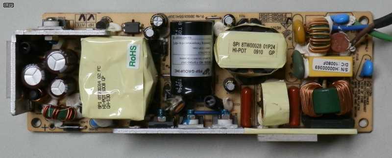
Figure 14.4 - Example Of A Very Compact SMPS
The above gives an idea of what 'compact' really means. The PCB is 150mm x 52mm x 25mm high, and it's packed with parts on both sides (all SMD parts are on the underside of the board). The supply is 24V @ 2.5A (60W), and has active PFC (power factor correction). This does increase the number of parts needed, but it decreases the mains input current substantially. It's designed specifically for lighting. The heatsinks are clearly visible, and it's designed to be mounted inside an aluminium enclosure to provide additional heat dissipation. If this supply fails, there's little chance that anyone would try to fix it (no schematic is available). Even the number of parts that can be salvaged is limited. Like nearly all switchmode supplies, it is intolerant of even a momentary overload, and it shuts down until the load returns to normal.
Idle current for the supply is 23mA and it dissipates 370mW. With a 1.5A load (36W output), the input power is 42.2W, an efficiency of 85.3%. The input current measured 200mA, so it draws 46VA and has a power factor of 0.97 (1.0 is 'ideal', but only achieved with a resistive load). Compare these figures to the values shown for the toroidal transformer in Table 13.1. The most significant difference is that a 'conventional' transformer can easily deliver twice its rated output to handle peaks, but an SMPS can handle only the maximum current it's designed for. There is no short-term peak current capability for the vast majority of SMPSs.
For another example (and the supply is still relatively low power, at 145W max.), <click here> to see a fairly comprehensive forward-converter SMPS intended for a small PC. The supply is made by DELL, and is a fairly good example, without being too complex (I expect that many will disagree on this point). The circuit has been completely re-drawn, as the original was not particularly clear and the file was a great deal larger. In case you don't know the terms, 'PE' means protective earth (ground) and 'POK' means power ok (aka 'power good').
A transformer-based supply will lose a few volts of output with a 2:1 overload (5A), but can handle 'normal' transient overloads without any problems. There's also no limit to the size of the filter capacitor(s), so you could use 10,000µF or 100,000µF caps with no adverse effects. It will be larger overall, but the total cost would be similar. Of course you can get a cheap SMPS too, but don't expect it to last very long. The SMPS shown will tolerate a 10,000µF cap at the output, but it will still shut down if you try to draw more than 2.5A - even momentarily.
Of course, not everyone wants to keep the same equipment for most of their life, but if it has to be scrapped in 5-10 years because a $2.00 IC has failed, that should be cause for some concern. Even if you don't care about the replacement cost, the waste of resources is still something that should be factored into the equation. Most switchmode supplies are not designed to be repaired, something that should be apparent if you try to get hold of the circuit diagrams for commercial products. Most are never released - not even to 'authorised repairers', and the 'repair' process is a replacement (until there is no replacement available). For some reason, many people never consider this piece of 'reality'.
One thing that's immediately apparent is that most SMPS are compact. While convenient, this ensures that parts that are affected by heat (notably electrolytic capacitors) will almost always be located right next to things that generate heat, such as MOSFETs, power resistors and diodes. In an ultra-compact design, this invariably means that longevity is compromised. The saving grace is that for audio, continuous power is fairly low, so continuous high temperatures are unlikely. However, a thermal switch operating a fan is always a good idea, although that means the circuit will gather dust over time.
If you do a web search for switchmode power supplies you'll almost certainly see lots of links to forum posts from people seeking help. In many cases the PCB will have one or more parts burnt out, with no indication as to what they once were. In a few posts you'll see that the person got the supply working again, but in many cases the only fix is a replacement. A very common fix is to replace electrolytic capacitors, but obviously that only works if the rest of the supply is functional. Unfortunately, catastrophic failures are common, leaving the PCB so damaged that even if the parts are available, a safe repair isn't possible.
The information presented in this article is intended as a guide only, and ESP takes no responsibility for any injury to persons (including but not limited to loss of life) or property damage that results from the use or misuse of the data or formulae presented herein. It is the readers' responsibility absolutely to assess the suitability of a design or any part thereof for the intended purpose, and to take all necessary precautions to ensure the safety of himself/ herself and others.
The reader is warned that the primary voltages present in all power supplies for amplifiers are lethal, and the constructor must observe all applicable laws, statutory requirements and other restrictions or requirements that may exist where they live. Secondary voltages are usually 'safe', but be warned that the voltage between +ve and -ve supplies will usually be at least 50V and may be over 120V for high power amplifiers. This is also considered 'hazardous', as is any voltage exceeding 42.4V peak AC (30V RMS) or 60V DC. Injury from secondary voltages is not common (except for valve amps, and especially microwave ovens - the latter have killed many technicians over the years!
WARNING: All mains wiring should be performed by suitably qualified persons, and it may be an offence to perform such wiring unless so qualified. Severe penalties may apply.
Be particularly careful to ensure that the DC supplies are insulated from each other and the common connection. Any contact between conductors may result in an arc, which can cause a fire or severe eye damage if you happen to be looking at it. Over-current protection by way of fuses or circuit-breakers is essential to ensure that the equipment and house wiring is protected from fault currents.
All power supplies must be fused and/ or protected by an approved circuit breaker, and all mains wiring must be suitably insulated and protected against accidental contact to the specifications and requirements that apply in your country. In most cases, there is a requirement for the use of 'a tool' (a screwdriver qualifies) to gain access to internal circuitry. It's now common for manufacturers to include security screws, to prevent access by non-qualified persons and/ or anyone attempting to gain access for servicing or other purposes.
Linear power supply design is not particularly difficult, and apart from making sure that you never exceed the recommended maximum voltage for any amplifier (or 3-terminal regulators for low current supplies), it's hard to go wrong. Smaller transformers will usually have a slightly higher no-load voltage, but it collapses more readily under load. A larger transformer will always provide a 'stiffer' supply voltage, but you need to ask yourself if this really matters. Transformers are very robust machines, and as long as you don't subject them to continuous overloads, most will last (almost) forever. Toroidal transformers are usually the best choice if you can afford the extra cost, and their much lower radiated (leakage) flux means that there are usually fewer problems with hum loops within the chassis.
A simple linear supply will operate with severe transient overloads (as found with music) without any risk. Provided the average transformer rating isn't exceeded, it won't care if you draw transient current of double (or more) the transformer's rating. A 200VA transformer will not be troubled if you draw an average of 50VA with peaks of up to 500VA. This would be typical for a stereo 150W/ channel amplifier driven to the onset of clipping with music having a 10dB peak/ average ratio. The use of large (10mF/ 10,000µF) filter caps will allow full dynamics. This is based on the 'rough-and-ready' formula described in Section 4 (Selecting the Transformer), where the transformer has a VA rating of 0.7 of the total amplifier output. For example, 0.7 of 300W (2 x 150W amps) is 210VA, but 200VA is close enough.
Don't discount the 'tried and true' E-I transformers from your final decision. Most are wound using separate sections of the bobbin for primary and secondary, making the likelihood of a primary to secondary breakdown very unlikely. Leakage flux can make the internal layout more difficult (hum loops), but if you only need a relatively small (say 100VA or thereabouts) transformer, there's no comparison when it comes to the cost difference. An equivalent toroidal will generally cost significantly more, and while it will be lighter and marginally more efficient, the cost doesn't always outweigh the benefits.
There's absolutely no difference in the 'sound' from an amplifier using a toroidal vs. E-I transformer, provided that the E-I transformer doesn't induce hum. Anyone who claims otherwise is badly mistaken. There are certainly measurable differences (notably regulation and no-load current), but these don't affect the amp's 'sound'. The difference in output power is so small (generally well below 1dB) that a listening test will not pick the difference. It's important to understand that we can measure things that can't be heard, but the converse is not true.
The idea of this article is to show the complete design process, but 99% of the time you'll buy a suitable transformer, bridge rectifier and filter caps, wire it up and it's done. Not including metalwork (which can be very time consuming for any build), a linear supply can be wired up and operational in no more than an hour, using point-to-point wiring and chassis mount electros. Should you buy a ready-made SMPS it will take just as long, but (and by necessity) you'll be much more careful. Last-minute chassis mods can be made to a linear supply without having to worry about small bits of metal bridging 0.5mm spaced IC pins, and it's very rare indeed that you'll ever need a fan for a linear supply. With many SMPS, a fan and excellent ventilation are a requirement, especially if it's very compact.
Ultimately, the power supply design is influenced by cost, size and weight. Switchmode power supplies are now very common in many commercial products (often with Class-D power amps), and no-one can claim that they are quieter than a linear supply. Many are not regulated, and simply use an 'off-line' rectifier and filter cap, followed by a squarewave inverter. The DC supply rails have 100/ 120Hz ripple, along with high frequency noise from the high-speed switching. These are generally not suited to DIY as noted in section 13, but the power supplies are available (often quite cheaply) as a separate item. Don't expect them to last 50 years though - some will be lucky to last for 5 years.
The degree of over (or under) engineering in a DIY project is determined mainly by size and budget. Weight is irrelevant if you don't need to carry it around on a regular basis. Provided you make sensible choices, the PSU is not difficult, and understanding why they behave as they do means that you aren't left guessing. Getting the supply 'just right' is rather satisfying, and building it so it will last a lifetime isn't hard once you have the right information to hand.
This article is an updated version of Linear Power Supply Design, which was written over twenty years ago. It's still (very much) worth reading, but it's a long article with a great deal of information. I've tried to keep this a little more succinct, but with a topic as complex as power supplies (despite their apparent simplicity) that's not easy.
The first two references are from other ESP articles, and where appropriate they have further references that indicate the original material used. The remaining references are for SMPS information.
Main Index
Articles Index