
|
|
| Elliott Sound Products | Snubbers For Mains Transformer Power Supplies |
 Main Index
Articles Index
Main Index
Articles Index
So, do mains (230/ 120V, 50/ 60Hz) transformers 'ring' uncontrollably when subjected to an impulse? Where does the impulse come from, and how do we stop it? This seems to be a topic of some considerable discussion on forum sites, and (predictably enough) one chap has convinced many of the forum dwellers that the answer is at hand. The real question is "Do I need one, and why?" This article hopes to shed some light on the matter, and is the result of many simulations and bench tests. The only impulse that will befall a transformer is due to diode switching, discounting other external influences such as mains 'transients' (commonly and incorrectly referred to as 'power surges') created by sub-station failures, nearby lightning, or perhaps from other network failures. Ultimately, we are (or should be) only interested if we can improve the DC, for example lower ripple, less high frequency noise, etc. Sadly, a snubber will not provide either, but nor will it hurt anything.
WARNING
This article describes power transformers that are connected to the household mains supply, and all 230/ 120V mains wiring is inherently dangerous and is capable of causing electric shock or death if contact is made by any part of your body. The reader assumes all responsibility for any injury (including death) caused by inappropriate safety precautions taken while performing tests, and it is required that anyone who undertakes any test described herein is qualified to work with mains voltages. It may be unlawful in some jurisdictions to work with mains wiring unless suitably qualified.
The number of myths that surround power supply design is quite astonishing. People seem to forget that the power supply for an amplifier or preamp has but one function - to produce DC. The DC then allows the amp (or preamp) to modulate the applied steady voltage in sympathy with the applied audio signal, but rejecting the DC (and most noise thereon) itself. The power supply itself has little influence over the sound quality, provided it is acceptably free of noise (no power supply will ever be 100% noise-free). Where noise is an issue, a simple resistor/ capacitor (RC) filter will reduce it to almost nothing, and this may be necessary for some microphone preamps (for example) where the PSRR (power supply rejection ratio) is minimal. An example of just that type of design is Project 66, because the transistor front-end has limited PSRR.
The easiest way to make a quiet power supply is to use a 'conventional' mains transformer, operated from the mains, and having a good filter network and (for preamps) a quiet regulator. An example is described in Project 05, where the rectified transformer output is heavily filtered using a two stage network, and the regulators are low noise variable types with capacitor bypass on the adjustment pin. The output noise is measurable, but it's so low that it has never caused anyone a problem when used with any number of other ESP projects. Most designs use 'standard' diodes (e.g. 1N4004 or similar for preamps, larger diodes for power amps), but some people prefer 'fast' or 'ultra fast' diodes which do reduce the turn-off transient (but again, don't change the DC at all).
This particular article ended up taking me into unexpected territory. The first obstacle was working out how to examine the small perturbations on a comparatively large mains frequency waveform, and that was solved with what I've dubbed a 'high frequency probe' (HFP). This removes the vast majority of the mains frequency, and allows one to examine the diode switching waveform up close and personal (as it were). Then it was necessary to work out if there is any likelihood of the diode commutation noise being transferred to the DC, and whether there's anything you can do to prevent it. In short, there's nothing that I would do any differently from what I've done all my working life in electronics. There really isn't anything that needs 'fixing'.
There seems to be a train of thought that 'ordinary' mains (i.e. 230V/ 120V 50/ 60Hz) transformers will ring uncontrollably due to rectifier diode switching. There are several ways that this actually can occur, but in general it's simply not something that needs 'fixing'. If it does happen, the effects are usually mitigated simply by adding a capacitor in parallel with the secondary winding(s). While this will always create a damped oscillation, it's at a significantly reduced amplitude and frequency. "Yes, but ..." you may hear from some, with a detailed analysis that may even include factors that don't necessarily exist.
The transformer's primary winding is connected to a very low impedance (and fairly well damped) source - the mains wiring (and subsequently any number of distribution transformers, sub-stations, etc.). The impedance of the 230/ 120V mains circuit is very low, typically less than 1 ohm for 230V or around 0.25 ohms for 120V. If this were not the case, it would be impossible to run a 2kW heater (for example) because the voltage would fall to an unacceptable minimum, affecting everything else on the distribution branch.
As with so many things in audio, there is always a fringe group that thinks (or even insists) that things that are completely inaudible somehow manage to ruin the sound, and that all manner of unnecessary and often expensive solutions are required for the 'perfect sound'. Most regular readers will be well aware that I consider this to be snake-oil, because if you can't hear or measure any 'interference', then quite obviously it isn't a problem. This extends well beyond power supplies of course - there are myths that affect the entire audio chain (even including the mains cable to the power outlet). This is a topic that doesn't warrant further discussion because most 'high end' power cables are verging on fraudulent.
Current regulations for conducted and radiated emissions are fairly strict, but I've seen nothing that would indicate that any low frequency transformer based power supply is able to produce emissions that would cause a product to fail the conducted emissions test. You can add a Class-X (mains voltage certified) capacitor in parallel with the transformer primary, and I have been able to verify that this does reduce conducted emissions slightly (I have a basic conducted emissions test set that I built many years ago). By definition (for a transformer), this capacitance is reflected to the secondary.
In reality, the poor power factor due to current waveform distortion is a far greater problem, but this isn't something that we can change easily (see Section 2.1). At present, the only way to ensure a good power factor is to use a PFC switchmode power supply. One can be confident that this will introduce far more high frequency interference into the nearby electronics, and while (usually) inaudible, this will always be far worse than any mains frequency transformer can produce. You could use a 'choke-input' filter (the diodes feed an inductor before the filter caps), but these are heavy, bulky and create problems of their own.
I was somewhat bemused when a reader asked a question about a circuit that's designed to work out the optimum snubber network (a series resistor-capacitor network, aka a Zobel network) for a transformer, and that's what led to this article being written. The important part of the alleged problem is that the circuit makes zero allowance for the fact that it tests the transformer with a 'small signal' stimulus, while the actual power supply is subjected to 'large signal' parameters.
Indeed, some users have said that they could easily see 'transients' when running tests, but failed to see anything when the supply was being used normally. No, I'm not going to provide references to the device or comments, because search engines will ultimately include these in search results, providing a degree of 'legitimacy' to something that is unlikely to give you a worthwhile outcome.
I've not provided any details for the 'optimum' type of capacitor, because the current through it is generally benign. As shown in the various screen captures, the peak (high frequency) voltage is only a couple of volts, and capacitor current is minimal when a series resistor is included. If a cap is used across the mains, it must be a Class-X2 type, but any polyester or polypropylene cap will be fine when used in a snubber circuit. Avoid multilayer ceramic caps, because they have a significant voltage dependency (capacitance reduces as voltage is increased).
First and foremost, you need an oscilloscope to perform the tests described here. Any attempt at developing a workable snubber/ Zobel network is utterly doomed without one. You must be able to see the waveform, and without a scope that's simply impossible. It might be possible to use a PC sound card instead, but I'd be rather nervous because you're looking at unknown waveforms, many of which could cause instant failure of the sound card (or even the entire PC) if you make an error and connect to the wrong place. Consider yourself duly warned!
If you examine the mains waveform (as it really is, not as a pure sinewave), and you'll see that the top of the waveform is slightly flattened. Rather than a pure sinewave, it's common for the mains to have a distortion of around 5-10% (depending on where you live, time of day, etc.), due primarily to the sheer number of power supplies (non PFC of course) and other non-linear loads that are connected at any given time. There may be hundreds of power supplies, all demanding current only at the peak of the AC mains waveform. Your hi-fi linear power supply is no different, even with the intervening mains transformer.
The following is a mains waveform scope capture at the secondary of an unloaded transformer. Transformers are excellent devices for this, as anything that happens on the primary side is reflected to the secondary (and vice versa), so it's not necessary to risk life and limb by connecting one's scope to the mains (a very dangerous practice unless you know exactly what you are doing, and even then it's still dangerous!).
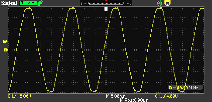
Figure 1 - Mains Waveform, Showing Flat-Topped Sinewave
For the following simulation results, I did use a pure sinewave, because it gives slightly worse (more pessimistic) results than the flattened AC mains waveform. We need to get some idea of the rate of change, not worst case (at the zero crossing) but close to the waveform peak where everything happens a bit slower. Near the crest of the sinewave (at the point where the diodes start to conduct), the rate of change for a 230V 50Hz waveform is only 21mV/µs at a peak voltage of 318V (and yes, you did read that right). That is very slow in anyone's language. It's about the same when the diodes turn off, although that doesn't influence the actual diode turn-off time. Even at the zero-crossing point (where the waveform passes through zero) the slew rate is only 102mV/µs (50Hz, 230V) or 65mV/µs (60Hz, 120V).
Remember that the end goal is to produce DC, which (pretty much by definition) is inaudible. Provided the DC is relatively noise free, the power supply rejection ratio (PSRR) of most opamps and power amps is capable of removing the majority of ripple, and (to a lesser extent) most higher frequency noise as well. Consider that the above simulation with a 10,000µF capacitor and a 1.2A current (at 30V DC) has around 1V p-p of ripple at 100Hz. This is easily dealt with by the vast majority of power amplifiers, and any ripple that appears at the amplifier's output should be close to the system's noise floor.
For example, a more-or-less typical power amp may show an output ripple of (say) 150µV RMS with a power supply using 10,000µF capacitors. That's better than -76dBV (referred to 1V), and may (might !) typically only be audible if you press your ear to the speaker cone. That works out to -85dB referred to 1W into 8 ohms. For a speaker with a sensitivity of 85dB/1W/1m, the output from the speaker will be 0dB SPL at a distance of one metre.
I tested a small range of transformers (suitable for power amplifiers and preamplifiers) to measure their leakage inductance - this is the property of any transformer that produces 'transients' when the current is suddenly interrupted. It's generally accepted that these 'transients' are created as the rectifier diodes turn off, but in reality it's rarely (if ever) a problem with linear power supplies. There is certainly a measurable DI/DT as the diodes switch on or off, and it usually does cause a momentary transient. I also measured the capacitance between primary and secondary, as this can create a resonant circuit combined with the leakage inductance.
The main purpose of the tests I did was to get an idea of the leakage inductance of the transformers, and how that interacts with the primary-secondary and diode capacitance in further testing. I checked for both primary and secondary leakage inductance. In brief that's the inductance caused by magnetic flux that 'leaks' out of the core, and doesn't interact fully with the transformer windings. It's shown in an equivalent circuit as a small inductor in series with the primary, but not sharing the magnetic core. There are other parasitic elements as well, shown in the following drawing. The values shown for the various parameters are based on Transformer #4 described in Table 1. C1 and C2 were not included (these are usually small parasitic capacitances that (more-or-less) represent inter-turn capacitances on the primary winding).
Figure 2 - Transformer Equivalent Circuit
The secondary leakage inductance can be approximated by measuring the leakage inductance of the primary, and dividing that by the square of the turns ratio. This will never be 100% accurate for a variety of reasons, most of which are related to the winding resistance which causes inductance meters to be somewhat inaccurate. To measure (approximate) primary leakage inductance, you short-circuit the secondary winding(s), and take an inductance measurement. It's somewhat beyond the scope of this article to examine more accurate techniques, and an approximation is usually quite acceptable unless you are dealing with transformers for SMPS.
For transformers used in switchmode supplies, leakage inductance is a very important parameter, and can create havoc with the drive circuit because it generates large 'spike' voltages, created by inductor-capacitor (LC) resonance. There is always stray capacitance in any circuit, and especially in wound components like transformers because of the winding layers and wires side-by-side.
The inference is that if this is a problem with switchmode transformers, then it must (by some strange twist of logic) also be a problem with low frequency transformers as well. The short answer (of course) is that it's not a problem at all, but that hasn't stopped people from claiming otherwise. There are very significant differences between the two types of power supply. A 'traditional' linear power supply operates at mains frequency (50/60Hz) with a nominal sinewave input. Because this has slow transitions, the chance of high frequency interference is minimal.
A switchmode power supply (SMPS) usually operates with frequencies between 50-300kHz (some may be higher or lower), and the switching waveform is rectangular. It has very rapid transitions from maximum to minimum and vice-versa, with high voltage waveform risetimes measured in microseconds. The rate of change (delta voltage vs. delta time, or DV/DT) can easily be 100V/µs or more, and that means that everything must be carefully optimised to ensure that electromagnetic interference (EMI) and potentially damaging transient voltages are minimised. A fault in a 10c part can easily cause an expensive SMPS to fail, and such failures tend to be catastrophic.
To equate these two very different topologies in any way is nonsensical. Linear power supplies have been the 'backbone' of all electronics for many years, but SMPS are now starting to become dominant in commercial products. DIY supplies are still most commonly built in the 'old fashioned' way, with a mains transformer, bridge rectifier and large filter capacitors. This is a more expensive approach, but 'linear' supplies tend to be extremely reliable, with examples aplenty that are 60 years old and still working fine. Very few SMPS will ever be able to match this. In most cases, even if a linear supply does develop a fault, it can almost always be repaired fairly easily. A transformer failure is an exception, but unless it's been heavily abused these are quite possibly the most reliable components ever.
| # | Secondary | VA | Primary | Secondary | CP-S ¹ | Construction |
| 1 ² | 12.6 | 2 | 762 mH | 2.35 mH | 48 pF | E-I |
| 2 | 15-0-15 | 80 | 6.4 mH | 130 µH | 347 pF | Toroidal |
| 3 | 25-0-25 | 160 | 1.8 mH | 180 µH | 292 pF | Toroidal |
| 4 | 28-0-28 | 200 | 8 mH | 570 µH | 347 pF | E-I |
| 5 | 30-0-30 | 300 | 1.63 mH | 115 µH | 622 pF | Toroidal |
- CP-S is the capacitance between primary (all leads shorted) and secondary (all leads shorted)
- The leakage inductance (primary and secondary) cannot be measured with an inductance meter due to the high winding resistance. Because it's so high, the readings will not be sensible. With a primary resistance of a bit over 1k ohm,
the inductance meter doesn't stand a chance. The same applies to the secondary. The values shown were calculated using the method described in the Transformers, Part II article.
Transformer #4 is a 'conventional' laminated core, rated for 230V input and 28-0-28V output, at a maximum load of about 200VA. I have a number of these, and they've been pressed into service for quite a few of my own projects. Primary-secondary capacitance is usually higher for toroidal transformers than 'conventional' types, due to the way they are wound. However, none showed any more than I expected based on the physical size of the windings.
It's immediately obvious that toroidal transformers show much lower leakage inductance than 'conventional' (E-I laminations) transformers. This is normal, because the magnetic path is completely closed, and the turns are evenly distributed around the core. The even distribution and low leakage is the reason that toroidal transformers are much less likely to cause induced hum current into a metal chassis than an otherwise equivalent E-I transformer. The characteristics of toroidal transformers are such that leakage inductance will have a higher Q than conventional designs, and a small amount of ringing is more likely.
Now, when a transformer is simulated using the values shown for leakage inductance, it is possible to create some damped oscillation as the diodes come out of conduction. I used the worst case (but not #1 as that's an exception) of 8mH (along with 347pF capacitance between primary and secondary), and sure enough, there's a brief period where the waveform shows signs of a damped oscillation - but it's only significant if you try to stop it by adding a capacitor! The frequency with a 220nF cap was around 38kHz in my simulation, determined by capacitance and leakage inductance. Without an external capacitor, not even the primary-secondary capacitance achieved anything 'interesting'. The diodes used in the simulation were 1N5404 (3A average current, 30pF capacitance at -4V reverse voltage).
Without anything across the secondary (other than the diodes and following filter cap and load resistor), there were exactly zero cycles of ringing - nothing at all, let alone anything to get excited about. So, adding a capacitor across the secondary is more liable to cause ringing (damped oscillation) than nothing at all. This being the case, there's obviously no requirement for a more complex network to eliminate something that doesn't normally exist.
One thing that simulators are very good at is highlighting the smallest 'deficiency' in a circuit, and this can show things that are almost impossible to capture on an oscilloscope. They also allow one to create a perfect component with no losses, and of course these do not exist on the test bench. So-called 'ideal' components are useful because losses can be introduced that exactly mimic the losses in a real part. However, simulators are very hard to set up so they mimic a real transformer, because there are non-linear effects that are difficult to estimate, and even harder to simulate.
Figure 3 - Transformer Response With Pulse Stimulation
In the above, the red trace shows the response when transformer #4 (as simulated) is pulsed with a +2V step with a rise time of 1µs (i.e. 2V/µs DV/DT). The source impedance is 100 ohms. The transformer has its primary shorted, and there is only the leakage inductance and primary-secondary capacitance in circuit. The green trace shows the result is the pulse is applied via a 10nF capacitor, but retaining the 100 ohm source impedance. Ringing is clear, and it would be much worse if the source impedance were reduced. The rectifier diodes were present for the simulation, but have almost no effect. The red trace shows good damping, with only a small overshoot, and no 'correction' is required. The turn-off transient is identical, but naturally it's inverted. Finally, the blue trace shows the effect of using a snubber/ Zobel network across the secondary, using a 10 ohm resistor and 100nF capacitor. As should be apparent, this makes matters (slightly) worse, not better.
It is possible to 'optimise' the resistance value to provide better damping, but there is clearly no need to do so. The best result was obtained with a snubber using 100nF and 68 ohms, but the overall effect is so small as to be considered negligible. Naturally, there's no reason not to include a snubber circuit, but equally there's no need for it in the first place. The response shown with nothing at all (red) is close to optimally damped, and there's no sign of anything that could ever prove troublesome. Remember that the stimulus used is a great deal faster than the mains frequency and diodes can achieve, so in use there will be almost no disturbance at all.
This may be a side-issue, but it's intended to demonstrate that small perturbations in the voltage waveform are actually the least of your worries. The current waveform shown below is the most common source of power supply noise, and if you don't understand this the rest of the article (or the use of a snubber) is close to pointless. All capacitor-input filters (by far the most common) create this type of waveform, and there is very little you can do to make it more 'sensible'. Note the peak amplitude of the current - over 10A for an RMS current of 3.1 amps. There is a big difference between the AC secondary current and the DC (1.2A).
A significant 'power' difference also exists - there is an input of 71VA (volt-amps = 3.1A × 23V) compared to an output of 36W (1.2A through a 25 ohm resistor). That's a 2:1 ratio of input VA vs. output power - the power factor is therefore about 0.5. About 2.5V is 'lost' due to transformer winding resistance and diode forward voltage drop. These are affected by the peak current, and not the RMS value.
Figure 4 - Transformer Secondary Current Waveform
The steady state secondary current waveform is shown above (the first couple of cycles aren't relevant and are not shown). There are relatively narrow peaks that coincide with the diodes conducting and passing current to the filter capacitors and load. The circuit is as shown in Figure 7 (below), with a 10:1 transformer (no-load output voltage of 23V RMS) 10,000µF filter cap and a 25 ohm load. Average current through the load is 1.2A with an average DC voltage of 30V. It is this current waveform that creates the most havoc in any power supply, and it requires careful grounding to ensure that the waveform isn't superimposed onto the DC output, nor coupled into adjacent wiring. Adding a snubber does not change this in any way, shape or form !
If the capacitance is reduced, so too is the RMS input current, but the peak current is increased slightly. For example, reducing the filter cap to 1,000µF means that RMS input current is 2.8A (10.9A peak, up from 10.5A peak)) and the power factor is improved (albeit marginally). However, there's a great deal more output ripple and a lower average output voltage so the supply's performance is diminished - in many cases unacceptably so.
Of course, simulations will only tell you so much, so transformers #3 and #4 were also tested on the workbench. #4 is almost a letdown, since the measured response was very close to the simulation, except that the measured waveform showed no sign of the small overshoot seen in the simulation. The real transformer has some additional losses (particularly iron losses) that can't easily be accommodated by simulation. This will affect all transformers of course - simulations often don't line up perfectly with circuits using real components.
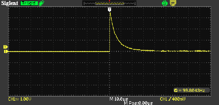
Figure 5 - Transformer #4 Response With Pulse Stimulation
When transformer #4 was subjected to a real impulse test, the waveform shown above was seen. The exact same stimulus was used (a ±2V squarewave), but the risetime of my function generator is much faster than I used in the simulator. The waveform is perfect - there is zero ringing, and therefore no reason to add a snubber network. There is a difference between this and the simulated version, largely due to losses that were not included in the simulation. A transformer is actually a fairly complex device in terms of losses, capacitance and inductance, and measured values don't always align with reality.
When a toroidal transformer is used, they tend to have a lower leakage inductance and a higher Q, so it's possible that some (slight) ringing will be observed. As simulated, this is innocuous, but if you really think it needs to be tamed in some way, a 10 ohm, 100nF snubber will do that very nicely for Transformers #3 and #5.
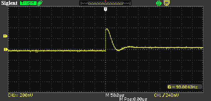
Figure 6 - Transformer #3 Response With Pulse Stimulation & Snubber
Without a snubber, transformer #3 looked exactly the same as #4, except that the timebase was 2.5µs/ division instead of 10µs/ division as shown in Figure 4. The amplitude was identical. Since the waveform was so similar I haven't shown it here, but I added a snubber to show what it can do. No calculations were done - I just used what was lying on the workbench at the time, a 10 ohm resistor and a 220nF capacitor. There are no complaints about the waveform - it's neat and tidy, the impulse is slowed somewhat and the amplitude is reduced, and the small amount of heavily damped ringing is close to perfect. However, the test is unrealistic, because the impulse is so much faster than anything that can occur in a real power supply. It's also still a 'small signal' test that doesn't tell us what the transformer will do when supplying a rectifier, filter cap and load.
If you look on-line for articles discussing leakage inductance in any detail, you'll find that almost all are related to switching transformers, where leakage really does make a significant difference. For mains frequency transformers it's hard to even find anything that discusses the topic, simply because it's not relevant for simple linear supplies. The situation is often different in TV receivers and other RF receiving devices because they are very sensitive, and even minute amounts of additional noise can cause interference.
Testing with 'small signal' transients isn't actually very useful. Yes, it can be done, but the difference in real terms (i.e. audible changes to the signal) will be immeasurable and inaudible unless there are layout errors that allow the tiny amount of noise generated to get into the audio path. As you'll see below, a small signal test does not replicate a transformer's actual performance in a real circuit.
There is no doubt whatsoever that snubber circuits are essential in most SMPS circuits, because they operate at high frequencies and with very fast rise and fall times. Using a snubber on a mains transformer won't hurt anything, and in a (very) few cases it might be needed to ensure that a product meets EMI testing requirements. Audibility is another matter altogether. It's possible that adding a properly designed snubber may lower the noise floor ever so slightly, but mostly you should not expect to hear a difference. You will certainly not hear any 'improvement' when music is playing, only when the system is (or is supposed to be) silent.
None of this means that the rectifier diodes won't cause interference, but if you use a toroidal transformer, simply ensure that the section where the primary and secondary wiring enters the transformer is oriented away from other wiring (that's where the leakage flux is the greatest). In most cases, this alone will be enough to minimise any audible noise. Likewise, keep input, DC and output wiring well away from the rectifier diodes and transformer leads, because high (and very non-linear) current passes through the transformer and bridge rectifier and associated wiring. Most of the noise generated in a linear power supply is the result of the highly distorted current waveform, a series of positive and negative current pulses as the capacitor(s) charge on each half-cycle.
If you still get audible noise, check all earth (ground) wiring before you resort to using snubber networks or caps in parallel with the rectifier diodes. There is a very real chance that caps in parallel with the diodes will make the problem worse, and a snubber network is unlikely to make a great deal of difference. It's one thing to run tests (with or without a dedicated 'test set'), but another entirely in a working circuit with high currents and 'real world' loads attached to the output of the filter caps.
However, just like the 'tester' referred to earlier, these are all small signal tests, and they don't tell us anything about large signal performance. The only way to test that is to build and test a power supply with a load approximating that which will be present in the final circuit. Unfortunately, it's difficult to see any small, high frequency disturbance in the presence of a large, low frequency waveform, and that lead to the next idea I had.
One of the problems faced when you are trying to look at small disturbances on large amplitude, low frequency waveforms is simply the scale of the waveform. It's not possible to see a tiny high frequency ringing waveform when the AC voltage is so much greater than the 'waveform of interest'. To make this task easier, a simple high frequency 'probe' can be utilised. It will show the parts of the waveform of interest quite clearly, but without overloading the front-end of the oscilloscope.
All you need is a 1k resistor and a 10nF capacitor. This will filter out anything below 16kHz, so you'll be able to see if there really is a problem, its magnitude and behaviour. In general, we can expect any disturbances to be at frequencies of between 10kHz and up to 25kHz. The filter I used has a cutoff frequency of 16kHz, but of course it's an easy matter to reduce (or increase) the cutoff frequency so you get the clearest possible look at any issues that exist. If you can't see any issues using this technique, then it's obvious that there's nothing that needs 'fixing'.
The idea is that you connect the transformer, rectifier, filter cap(s) and a suitable (preferably representative) load resistor. The latter should be selected so it will draw the same current as the circuitry that will be powered from the supply. If the load is variable (such as a Class-AB power amplifier), then use your own judgement, but the load current should be about the same as the power amp's quiescent current. You can (of course) vary it as needed to see if that makes any difference.
Armed with this tiny circuit, you are in a real position to see whether there is any ringing or not, and the magnitude and frequency of the waveform. It also lets you experiment with a snubber network if you think you need one, not with some ill-conceived 'tester', but with the actual power supply circuit. You can see instantly if there's a benefit or otherwise of a capacitor, snubber, or a combination of the two. The drawing below shows the circuit, and how it's connected to your power supply.
Make sure that the power supply outputs are floating (not grounded anywhere !), because you will ground one of the transformer output leads with the ground clip of the oscilloscope. This won't have any appreciable effect over what you see on the oscilloscope, because the ground point is simply a reference, it's not an absolute requirement for most circuits. If you have a dual supply (± voltages, the transformer centre will be grounded anyway, and you can examine either AC winding (both will require a snubber if you want to go ahead with that).
Figure 7 - High Frequency Probe (HFP) Connections
This is (as near as I can tell) a new approach to looking at the disturbances created by rectifier diode commutation. I have searched, but didn't find anything even remotely similar anywhere. Not that it's groundbreaking of course - it's just a very simple high pass filter that lets you see things that would otherwise be obscured by the 50/60Hz waveform. The benefit is that you can determine not only whether there is a (potential) problem, but exactly what happens when you add a capacitor or snubber. In some cases it may be necessary to increase the value of Cf (or Rf) if the observed frequency is less than 10kHz. Using 22nF (or 2k2) will let you see down to 7kHz, but you will get a little more of the 50/60Hz waveform (although it will be reduced by over 40dB).
Note that one of the transformer output leads is grounded by the scope. This is a temporary connection, but you have to do it that way to ensure that you measure the actual voltage across the secondary. The snubber is shown as optional, and 'SOT' means 'select on test'. With this, you can see any disturbance, and the three screen captures shown let you see the waveforms I measured during testing. The values shown for the snubber are a good starting place. In the waveforms captured below, I used 10 ohms and 220nF, simply because they were to hand at the time.
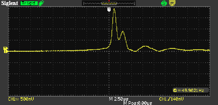
Figure 8 - Transformer #3 Response With HFP (No Snubber)
The transformer was the same type as the one used above (#3), but the one used for these tests was already wired to a rectifier and a pair of 5,600µF filter caps. I used an input voltage of 120V (50Hz) with a nominal 16 ohm load (roughly 2A DC output current), and had an unloaded voltage of 36V DC at the output (between the +ve and -ve terminals). The impulse is clear - a 2V peak lasting for ~2µs, followed by a few rapidly diminishing ripples. Now, I know that this isn't audible when an amplifier is connected (the supply is a test jig for power amplifiers), but I suppose it might not look 'pretty'. The pulse appears at the instant the diodes turn off. For clarity, only one pulse is shown, but obviously they occur at twice the mains frequency (100Hz in my case), and with alternating polarities because the rectifier is a full-wave bridge.
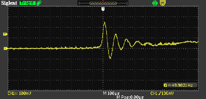
Figure 9 - Transformer #3 Response With With HFP (220nF Capacitor)
When I added a 220nF capacitor directly across the secondary winding, I obtained the waveform shown above. The amplitude is reduced to 250mV, and there are more 'ripples' (indicating ringing), but at a lower frequency. Note the oscilloscope timebase setting - it's now 100µs/ division, and the oscillation is at about 10kHz (a little below the filter cutoff frequency). This isn't a bad result, and personally, I would be perfectly happy with that. This is an arrangement I've used before, largely because it's a cheaper (and smaller) option than an X-Class cap across the mains. This was done purely to ensure compliance with conducted emissions tests, not because it made anything sound 'better'.
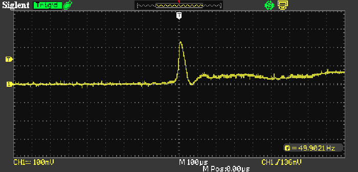
Figure 10 - Transformer #3 Response With With HFP (220nF, 10 Ohm Snubber)
When a 10 ohm resistor was added in series with the 220nF cap, the above waveform was obtained. This is as good as you'll get in any real circuit, and it's as good as you need as well. Again, I would not expect to hear the slightest difference through an amplifier connected to this supply, regardless of the presence or otherwise of the snubber. However, the result shown in Figure 10 is close to perfect - the damping is ideal, and the peak amplitude of the diode commutation 'disturbance' is reduced to 220mV.
If you wanted to determine the absolutely best possible snubber circuit, you can just use a resistor and capacitor decade box. You could also build a simple test circuit using (say) a selection of switched capacitors and a 100 ohm or 1k wirewound pot, although a carbon pot would probably be alright for testing as average power is quite low. Whether this is something you think you need is up to you, but the chances are that a snubber similar to the one used for Figure 10 is likely to work well enough over a range of transformer, rectifier and filter circuits.
While I had things set up, I next tested a 'wall transformer' - 230V in, 12V out, at 1A (12VA). The test supply used a 6,800µF filter cap and a 40 ohm load, providing an output of 360mA at 14.5 volts. This was checked using normal 1N4004 diodes and with MUR240 'ultra fast' diodes to see if it made any difference. The answer is yes and no - "yes", the impulse as the diodes turned off was reduced from a peak of just over 6V to about 1.8V, but "no", the DC was resolutely unchanged (even when the 'HFP' circuit was used to monitor it). The optimum snubber turned out to be 100nF in series with 100 ohms, and I made no attempt to measure the leakage inductance.
Click here to see a sub-page with the waveforms I captured. It's actually worth looking at because the results are mildly interesting. 
There is one special case where the use of either exceptionally slow or high speed diodes and snubber circuits may be required. For people in fringe reception areas for radio or TV, the receiver operates at maximum gain and it may be susceptible to RFI/ EMI created by a conventional linear power supply. If this is the case, even relatively small amounts of EMI generated by diode switching may be sufficient to cause interference. There are no exceptionally slow diodes any more, as they used rather ancient technology that's no longer used by anyone. As shown above, using fast (or ultra-fast) diodes and a properly designed snubber may help to reduce (or even eliminate) any interference.
If this is a problem, the final circuit should include the fast diodes, snubber network(s) and a properly designed EMI filter, either stand-alone or integrated with an IEC mains socket. The chassis also has to be metal, with all panels in intimate electrical contact with each other. Gaps in the metalwork need to be kept small, and good electromagnetic screening relies on the panels being electrically joined along the full length of every joint. You are building a small Faraday cage, with the intention of containing both radiated and conducted emissions.
If EMI is an issue where you live, every electrical device in the home will need to be 'EMI free'. In some cases, you may find that there is annoying buzz when a particular appliance or even light (assuming CFL or LED lighting) is turned on. Turn it off and the noise stops - this is a clear indication that EMI is a problem. Without extensive (and expensive) equipment, it's usually not possible to determine if the noise is radiated (often using mains wiring as an 'auxiliary' antenna) or conducted (passing interference directly into the mains wiring). Modern emissions standards may (or may not) have been complied with, and it's not uncommon for certain Asian manufacturers to apply CE, UL, CSA, VDE and other standards markings to products that have never been even tested, let alone certified.
CE compliance is particularly strict, and genuinely certified products will usually not cause problems. Clearly, certification is not an option for a DIY project (it's very expensive to have done in an accredited test laboratory), so the constructor is pretty much left to his/her own solutions, should they be required. Hopefully, this material will help if a project turns out to cause issues. Mostly, simple linear supplies with no special precautions will be perfectly alright, and will not need any of the measures described. However, there can be exceptions for a variety of reasons.
If EMI is a problem for audio equipment, the most likely way for it to cause problems is via the input leads. These should always be shielded, and good quality connectors help to minimise issues with contact resistance and/or corrosion which can allow the leads to pick up external noise. It also helps to ensure that input leads and power leads are separated, so there is minimal mutual coupling.
The test methodology that stirred up this particular hornet's nest is actually (at least in part) the cause of the very problem it's designed to fix. Yes, I'm fully aware that this is a paradox, and that's the issue. Stimulating a transformer to ring by sending a fast transient into the secondary via a capacitor is fatally flawed on so many levels it's hard to figure out where to begin ...
If exactly the same pulse is delivered to the secondary via a resistor (with the primary shorted) and without a series capacitor, there will normally be no ringing (as shown above in simulations and scope captures). However, this is (as noted earlier) a small signal test, and it's not the same when used at full mains voltage with a rectifier, filter cap and load. Even transformers shown above that showed no sign of ringing with an impulse test performed quite differently when wired up into a complete power supply.
Building a test circuit that first creates the illusion of a problem, then claims to provide a 'simple fix' is obviously of little use to man or beast. The article that prompted all of this goes into great detail, and has lots of maths in the appendix that describe the phenomenon of ringing. However, the writer appears to have missed that the 'injection' capacitor was the root cause of ringing in the first place. Once that's removed from the equation there may not be a problem to fix! If there really is a problem, it's far better to analyse it in the final circuit with a representative load.
This was tested and verified both in simulations and on the workbench, with the two tests providing results that are so close that it confirms the methodology and the results. The important thing to recognise is that without a snubber the impulse waveform caused by diode switching will be (or will be very close to) critically damped. Adding the snubber deliberately 'under-damps' the circuit, and you need to see some overshoot before the waveform settles. When this is done, the impulse amplitude and harmonic content are reduced by a worthwhile margin.
If a snubber is added with the values determined using the method described here, any ringing can be suppressed. However, it's really not necessary to do so, because it does no harm. It might look 'nasty' if you haven't come across it before, but the effects are largely benign. The DC output is not affected whether the snubber is in place or not, and the only real difference is that there is a small but potentially useful reduction in high frequency conducted emissions. The main cause of mains waveform distortion remains the very non-linear current waveform, which is a far bigger problem than a short burst of high frequency noise on the transformer's secondary winding.
This is an article where, in an attempt to prove that something was completely unnecessary, I discovered that this may not be the case. However, I also found nothing to suggest that a snubber is actually needed. There are a couple of other articles on my site that started the same way, and this the nature of running proper testing. The findings here don't mean that I will recommend a snubber, because I know from many years in electronics that it mostly doesn't matter at all, and there's usually very little to be gained in a well designed circuit. Ultimately, the only thing that matters is the DC from the power supply output(s), and this is unlikely to be affected in any way.
I used the same HFP circuit to examine the output (DC) waveform, and because all of the low frequency ripple was removed, I was greeted by a straight line with vestiges of high frequency noise superimposed. Nothing to get concerned about, since I was able to increase the scope's sensitivity to 20mV/ division, and the noise was just visible. Adding a capacitor by itself or the snubber made exactly zero difference to the observed noise, so it's safe to assume that this will probably be the case with your power supply as well. This was also tested by simulation, and even the extraordinary resolution available from the simulator failed to show the slightest difference in the DC output with or without the snubber.
It's not uncommon to see very small 'spikes' on the DC waveform when you use the HFP circuit. These coincide with the charge current from the rectifier being delivered, and are largely due to the finite impedance (mostly ESR) of the filter capacitor. It's common for people to include low value film capacitors in parallel with electrolytic caps, but these achieve nothing useful unless the powered circuit operates at radio frequencies. Film or ceramic caps are required in parallel with opamp supply rails (close to opamps or power amps) to counteract the inductance of the supply wiring and/ or PCB tracks.
If you like the idea of using a snubber circuit at the transformer's secondary (or secondaries), there is no reason not to use one. Likewise, feel free to use ultra-fast diodes if it makes you feel any happier. Most of the time, you can simply use a 10 ohm resistor in series with a 100nF capacitor. There's no 'optimisation' here, but that combination can be expected to work well enough for most transformer/ rectifier combinations. Don't expect the snubber to make the slightest difference to the audio, because it almost certainly will do no such thing. To optimise the snubber, as noted earlier I suggest a resistance decade box or a 1k pot, and a choice of perhaps three of four different capacitor values. You definitely need the high frequency probe, as that makes everything of interest so much easier to see.
There is no real 'optimum' value for the snubber - it's a compromise between impulse amplitude and settling time. Aim for a slight overshoot as shown on the second page of this article. If we talk of damping (or damping factor), this is the opposite of Q ('quality factor'), and you should aim for damping of around 0.5 which is a Q of unity (damping is equal to 1/2×Q). The waveform obtained with no snubber will generally be critically damped already, and the snubber circuit actually deliberately creates a slightly underdamped system.
All tests should be carried out with the transformer and rectifier operating normally from the mains, and with a load that approximates the load that will be applied in normal use. 'Small signal' tests are far less useful, and are unlikely to give the same results as a 'full scale' test at normal mains voltage and frequency. I have verified that once a snubber is determined, its performance is not load dependent, so it will work with variable current loads (such as power amplifiers). Naturally, you will ensure that mains connections are secure and wired to the appropriate standard to ensure you aren't electrocuted while testing!
EMI is one area where there might be a small impact, but in general it's not an issue for the vast majority of DIY constructors. The section above should help if you do experience interference from your latest project, but in most cases there will be nothing needed other than sensible wiring practices. Switchmode power supplies create vastly more noise than any linear supply, and are more likely to cause interference than any linear supply using a mains frequency transformer.
None of this will affect the DC, and therefore cannot affect the music via the DC supplies. If nothing else, it gives you something new to play around with, and it's also a worthwhile learning tool so nothing goes to waste.
There are no references for this article, because the tests I did are somewhat unique (for mains transformers) and the method I used to determine leakage inductance for transformer #1 does not appear to have been published before. That doesn't mean it hasn't been published, but I did some extensive searches and could find nothing similar. The same applied to the 'HFP' (high frequency probe) that lets you look at the impulse without any mains frequency AC getting in the way.
As for references to the 'tester' mentioned in this article, I have no intention of giving it any legitimacy by providing a link to it. While the author has obviously spent considerable time putting his information together and it probably works well enough in practice, the method described here is a lot easier and cheaper. Some readers will recognise the info I'm referring to immediately by the description, and those who don't recognise it don't need it anyway.
Main Index
Articles Index