
|
| Elliott Sound Products | Snubbers For Mains Transformer Power Supplies - Part II |
Snubbers For Power Supplies - Are They Necessary And Why Might I Need One? - Part II
© Rod Elliott - ESP (2019)
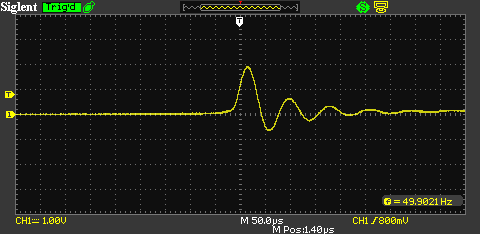
This sub-page shows supplementary waveforms for wall transformer and rectifier combinations. The transformer is 12V at 1A (12VA), connected to a bridge rectifier using 1N4004 and MUR250 diodes. All waveforms were captured using the 'HFP' (high frequency probe) described in the main article. The probe was modified to use a 10nF cap and 2k2 resistor, because the frequencies are a bit lower than with larger transformers having less leakage inductance. In particular, look at the amplitude of the spike waveform in Figures 11 and 14, showing that fast rectifiers do reduce the diode switching noise (but we still don't really care). The amplitude (and speed) of the impulse is reduced using a 100nF/ 100Ω snubber (Figs. 13 & 16). and this might be useful in test equipment.

| 
| 
|
| Figure 11 - 1N4004 Diodes, No Snubber | Figure 12 - 1N4004 Diodes, 100nF Capacitor + 10 Ohms | Figure 13 - 1N4004 Diodes, 100nF Capacitor + 100 Ohms |
The second set of traces was obtained from the same transformer, filter cap and load, but using 'ultra fast' MUR240 diodes instead of 1N4004 diodes. The spike is smaller with the fast diodes, and the snubber reduces the amplitude further. Otherwise the results with a snubber in place are very similar to those using 1N4004 diodes. The amplitude of all ringing waveforms is reduced, but the DC output was unchanged.

| 
| 
|
| Figure 14 - MUR240 Diodes, No Snubber | Figure 15 - MUR240 Diodes, 100nF Capacitor + 10 Ohms | Figure 16 - MUR240 Diodes, 100nF Capacitor + 100 Ohms |
From all of this testing, it's quite obvious that there are some significant differences between the use of 'ordinary' and fast diodes, and that snubbers can (and do) reduce the amplitude and frequency of any ringing waveform. However, they don't affect the DC at all, so if your wiring is routed carefully (keeping transformer leads well away from audio circuitry for example) you won't hear any change. 'Lead dress' (the way wiring is routed and segregated from other wiring, whether DC or signal) is always important, and getting it wrong can lead to considerable buzz in the audio. Adding snubber networks might be easier than re-wiring a project, or it might just let you imagine that proper lead routing is 'not important'. This isn't a wasted exercise, but in most cases you won't get any real benefit.
In general, more and greater problems are created by incorrect placement of the main earth/ ground in the chassis, or by not ensuring that all DC feeds are taken from the filter capacitors, and never from the rectifier. It's quite surprising just how much difference this can make - a mere 10mΩ (0.01 ohm) will develop 20mV of very nasty-sounding noise with a peak current of 2A, and that doesn't even consider the inductance of the wiring.
When a capacitor or snubber is added, the effective frequency is reduced (the uncorrected spike waveform has harmonics extending from the mains frequency well into the low RF band). This is the reason that adding a capacitor or snubber can ensure compliance with conducted emissions tests. Again, this isn't generally necessary, as most transformer based supplies will pass anyway.