
|
|
| Elliott Sound Products | Project 66 |
 Please Note: PCBs are available for this project. Click the image for details.
 Main Index
Projects Index Main Index
Projects Index
|
This simple design has very low noise, close to the theoretical minimum, high hum rejection and variable gain with a single rotary pot. It is similar to that used in many professional grade mixing desks and can form the basis of a no compromise recording mixer for live work.
The design consists of differential compound pairs of transistors with a common mode (floating) gain control connecting the emitters of the pair. The compound (Sziklai) pairs of 2N4403 and BC549s are far more linear than any single transistor. The circuit is differential in and out and therefore requires a balanced to unbalanced buffer to give suitable output for the next signal stages of a channel in a mixing desk. This is provided by a high performance op-amp differential gain stage, which can be a TL071 or similar IC of your choice. The stage has a gain of ~4.6 or 13dB and that sets the maximum input level at about 1.5 volts RMS before clipping. This equals an SPL of over 150dB with a typical microphone!
Full gain is 1000 times or 60dB (actually 56dB with R9 as 22Ω). Distortion is low to unmeasurable because it is below the noise level at high gains. The CMRR (Common Mode Rejection Ratio) is well over 60 dB and better than any available mic cable as far as hum rejection is concerned. The bandwidth extends beyond 100kHz, and no RF suppression is shown as it has proved unnecessary in practice. The input impedance or load on the mic is set by the two 3.3kΩ resistors. This will suit almost any mic with a nominal impedance of 150 to 600 Ω.
Note that the microphone and input impedances should never be 'matched', as that imposes a 6dB noise penalty. The noise level remains the same, but the mic's output voltage is halved. Impedance matching may cause a (small) change in the sound with some mics, while in some others ('condenser'/ capacitor mics) the mic may distort at a lower then normal SPL. Almost all professional mic preamps use an input impedance of at least 2.2kΩ. The suggested parts for this project give an input impedance of 6.6kΩ, which will provide minimal loading on any mic. The higher than 'normal' input impedance causes the unterminated noise to be a little higher than you may expect, but a mic preamp with no microphone isn't useful. 
It's generally accepted that a mic preamp's input impedance should be ~10× that of the microphone (although this is not an absolute requirement), so this project can be used with mics up to 600Ω without problems. Mic preamps are almost always measured (for noise) with a source resistance of 200Ω. This means a noise level from the resistor alone to be 1.81nV√Hz, or 0.257μV (-129.6dBu). Any noise from the preamp is added to the source noise. Noise signals do not add algebraically because they are random, so 250μV of input noise plus 250μV of preamp noise gives a total of 354μV, not 500μV.
The input stage is configured for least noise and this has meant a non IC approach. There are some special ICs that can be used for mic pre-amps, they contain a circuit like this one except fabricated on one chip. Examples include the SSM2017 (now obsolete) or the replacement INA103 (rather expensive) or similar.
Components should all be readily available except for the 10kΩ pot for the gain control. This really should be a reverse log taper - or else use a multi-position switch with 6 dB gain steps covering the 60 dB range of the circuit. Ideally it will be 'make-before-break' to minimise switching noise.
Editor's Note - Alternatively, a standard log pot can be used, but wired 'backwards'. This will work fine if it is labelled 'Attenuation' instead of 'Gain'. As the pot is advanced clockwise, the gain is reduced (attenuation is increased). Maximum gain will therefore be applied when the pot is fully anti-clockwise. Note that this is not a problem that is specific to this circuit - all IC mic preamps have exactly the same problem.
The ±15 Volt power supply is important too, it must be regulated and low noise. If the usual voltage regulator ICs are used I recommend fitting a post filter consisting of a 10Ω resistor and a 470µF capacitor to remove any noise generated in the regulator ICs. Some 7815 ICs could be sold as noise generators, the adjustable voltage ones (LM317, LM337) are very much quieter. A single regulator board may be used to power multiple preamps, with each preamp having its own post filter circuits. Because of the extensive filtering applied, the Project 05 power supply is recommended for this preamp. The preferred supply voltage is ±15V.
Good quality components should be used with metal film resistors in the collectors and emitters of the input pairs for least noise. Where a resistor has significant DC voltage imposed on it in high gain circuits always use low noise types. Metal film resistors are about the best only bettered by wire wound which is a bit impractical. Avoid cermet, metal glaze, and carbon types. Also avoid bead tantalum capacitors, as they go leaky and crackle. They are just about the most fragile electronic components made. The 100nF capacitor (C6) should be mounted as close as possible to the opamp supply pins - a multilayer ceramic cap is recommended for best bypass performance at high frequencies.
Approximate DC voltages for the input stage are shown in green. These will vary slightly from one unit to the next due to different transistor emitter-base voltages, but most units will be fairly close. If you measure a radical difference, you've made a mistake during construction.
The 1,000µF capacitor can be a normal electrolytic of 10 or 16 volts rating. There is usually no problem with zero DC bias on modern electros, provided the reverse voltage remains below 1V. It won't exceed 100mV in this role. All other electros should be 25V rating as a minimum.
Upon checking the published specs for the SSM2017 in regards to noise, my workshop version of the preamp measures at least as good with a 200Ω source resistance (typical of most dynamic microphones).
EIN = 0.27µV RMS, 20 kHz bandwidth with 200Ω source.
= 1.9nV per root Hz (1.9nV√Hz - equal to spec for SSM2017)
Noise Figure = 0.9 dB relative to 200Ω resistor
I would suggest that 1% metal film resistors should be used throughout this circuit - the additional cost is negligible, and this will also ensure that the balanced buffer stage (U1) is properly balanced. Even a small error in the input and feedback components will degrade the common mode rejection.
Like Phil, I also recommend against the use of tantalum capacitors, and regular readers will notice that I have not suggested them for any project. The only capacitor fault I have ever had to track down with an intermittent short circuit was a tantalum bead type - it was neither fun, nor easy to find. 
As with all circuits presented on these pages, feel free to experiment. The 2N4403 transistors may prove difficult for some readers to obtain, and BC559 or BC560 transistors can be substituted with a slight increase in noise. I would expect that any increase will be acceptable for most applications. Performance should otherwise be much the same as described. I used BC559s in my test preamp which gets regular use - it is very quiet with all 'standard' microphones. The BC559/ 560 have a noise figure of 1.2dB
Note: The 2N4401/3 (NPN/ PNP) transistors are switching types that someone discovered just happen to be very low noise. They have been used by a number of manufacturers - often with the type numbers removed to keep the 'secret'. It's no longer a secret, and while there are quieter devices, most will be either hard to get, SMD, or both. For more info on noise in general, see the article Noise In Audio Amplifiers.
The preamp is ideal for portable use, and can be operated from a pair of 9V batteries.
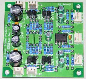
In all, this preamp is highly recommended for professional or semi-professional use, wildlife recording or just experimenting. As you can see from the photo, the board is very compact, and I have described a phantom feed supply and distribution board elsewhere in the project section, along with a phantom powered microphone amplifier and a series of microphone projects.
When using the preamp, don't be alarmed when you hear a significant noise output with high gain but no microphone connected. This is completely normal, and is mainly due to the thermal noise generated by the two 3.3k input resistors R1 and R5. If you ever needed proof that resistors make noise just by being there, this is it. Once a microphone is connected, the low impedance of the mic itself short circuits the resistor noise and the preamp will be as quiet as claimed. The quoted noise figure is with a 200Ω input (source) resistance.
The noise from a 200Ω resistor at 27°C is roughly 0.26µV (260nV), not huge by any means, but certainly something that must be considered. For more detailed information on noise and where it comes from, see Noise In Audio Amplifiers.
Please be aware that this preamp must not be connected to a mixer that provides phantom power, as it will destroy the opamp. If it's planned to use it to provide additional gain, you must protect the outputs with zener diodes, series resistors and coupling capacitors. Likewise, it you intend to add phantom power to the input of the preamp, a protection scheme similar to that shown in Project 96 (see Figure 2).
When looking at IC specifications, you often see noise specified as nV√Hz. This doesn't mean a lot to most DIY people, but it's actually easy to calculate the equivalent input noise from this. If we assume the bandwidth to be from 20-20kHz, that's a range of 19980 Hz.
Now, take the square root of this value and multiply by the noise figure quoted. For most normal audio work, a value of 141 is fine for the square root.
Equivalent input noise (EIN) = 141 × Noise (nV) ∴ Output noise = EIN × Gain
If the stage gain is 100 and EIN is 1µV, output noise is 100µV. It is now easy to see if this will cause a problem with your signal. For example, if the signal you are trying to amplify is only 1mV, the output signal is 100mV, and SNR is ...
SNR = 20 × log ( VSIG / VN ) ∴ SNR = 20 × log ( 100mV / 100µV ) = 60dB
You will have a 60dB signal to noise ratio (SNR). If your input signal is 50mV, SNR is now 94dB, but with 5V RMS output you have no useful headroom if you operate with a gain of 100. With lower gain, EIN increases (as with all microphone preamps). With 20dB of gain and a signal output voltage of 50mV × 10 = 500mV, it's not unreasonable to expect the input noise to have risen to around 12nV√Hz, so you will get the following ...
EIN = 141 × 12nV√Hz = 1.7µV ∴ EOUT = 10 × 1.7µV = 17µV ∴
SNR = 20 × log(500mV / 17µV) = 89dB
In some cases, thermal noise in the source resistance (the microphone's voicecoil or transformer winding) will dominate. Even if external thermal noise is zero, there will always be extraneous noise in any real recording environment, and expecting ambient noise to be more than 60dB below the signal level is not usually realistic except for very loud sound sources. The SPL at the microphone when recording drums might be 120dB, but there will be huge amounts of 'spill' from other drums in the kit, so the ambient noise is academic.
Another form of noise specification you will see is the 'noise figure'. An amplifier with a noise figure of 1dB means that the amplifier itself makes the specified input resistance 1dB noisier than a 'perfect' noiseless amplifier would do. To put this into perspective, a mic preamp with a quoted noise figure of 3dB would have the same equivalent noise input as a resistor of the designated value - typically 200Ω (260nV from both the resistor and the preamp's input). Note that equal noise voltages sum to +3dB not +6dB, because noise is uncorrelated (random phase).
No mic preamp is noise free, and nor is any resistance above zero ohms or 0K (zero Kelvin, roughly -273°C). Likewise, all recording environments have a measurable background noise, as do listening environments. The laws of physics demand that we have noise whether we like it or not.
| Main Index
Projects Index
|