
|
| Elliott Sound Products | Project 96 |
 Please Note: PCBs are available for this project. Click the image for details.
For reasons that I find somewhat puzzling, there are very few decent 48V phantom power supply schematics available on the Net. Those that I have seen are either very crude, or require the use of a special transformer that (naturally) is all but unobtainable (or both). In contrast, a 15-0-15V transformer can be obtained almost anywhere, but alas, does not have enough voltage after rectification and filtering.
Fortunately, this is not a problem, as a voltage doubler supply will give more than enough voltage, and is easy to build. The design featured here uses just that, and allows the use of a readily available transformer (ideally 12-0-12V or 2×12V secondaries in series) and other low-cost parts, to give a supply with extremely good performance. As shown, there is no short circuit protection, but a phantom supply is unlikely to be shorted anyway, so this is not a limitation.
Of the designs that are available on the Net, there is the supply shown in the P30 mixer (see Figure 3), which is similar to the design shown here, but is not as refined.
Another version of phantom supply (reasonably common) uses an oscillator and voltage multiplier to provide the 48V (or thereabouts) supply, but these are not suitable (IMO) due to very poor regulation and an inherent inability to provide enough current. The maximum current that can be drawn from a standard phantom circuit (using 6.81k resistors) is 14mA into a short circuit. Since all phantom powered systems need some operating voltage (a typical value being around 10V), the maximum practical current drawn by each powered circuit is around 11mA. Naturally, some will draw less than this. The voltage multiplier supply will be struggling to supply even this meagre current, and will have high battery drain as well.
There are also quite a few suggestions that you can use as little as 18V for phantom powering (using a pair of 9V batteries), but unless the microphone or DI box (for example) is specified to operate at such a low voltage, then I would not recommend it - headroom will be reduced dramatically, and distortion will be a problem at even relatively low levels. Some equipment will not work at all. The lowest recommended phantom supply voltage is 30V, and I consider even that to be too low for most things.
Output current of this design is rated at 100mA at 48V, although you will be able to get more - 200mA is not unreasonable with a few changes, and even then output ripple can be expected to be well below 1mV. Simulation gives a figure of 10μV peak to peak at 200mA, but this is likely to be rather optimistic. In most cases, a transformer with either 2×12V (ideal) or 2×15V secondaries will be used. If you only need to power 2-6 mics, a 5VA transformer will suffice, but a 10VA transformer is a better proposition overall.
It is probable that few people will ever need the maximum suggested output current, since 200mA is capable of supplying up to 20 phantom powered microphones at once. My recommendation is to keep the maximum current to 100mA or less.
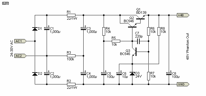
The circuit is shown in Figure 1, and as described above, uses a voltage doubler rectifier. Diodes D1 and D2 are 1N4004 or similar. From there, a pair of resistors provide additional smoothing to the secondary filter caps. R3 is used to balance the voltage across C3 and C4, and must not be omitted.

Figure 1 - 48V Power Supply (P96A PCB)
The regulator shown was a very common topology prior to the introduction of 3-terminal regulator ICs, and is used here so that high voltage regulators are not needed. These are much harder to get than the standard versions, and still require additional circuitry because 48V versions are not made. Although the circuit looks complex, it is very easy to build (especially if the PCB is used).
The zener diode is the reference voltage, and 1/2 the output voltage is compared to the zener voltage by Q3 (the error amplifier). If output voltage increases (because the load current is reduced for example), Q3 is turned on harder, removing base drive from Q2 (and hence Q1), reducing the output voltage to the preset value.
As can be seen, there are no adjustments, and this means that the 48V may be a little higher (or lower) than rated. This is not a problem however, and all phantom feed microphones will handle the variation without any problems at all.
Load regulation is far better than you might expect, with typically 100mV variation between full load (100mA) and no load. At 200mA load, the voltage falls by less than 150mV compared to the no-load voltage. Line (input) regulation is also quite good, with less than 200mV output change with +20% and -20% input voltage, with a load of 100mA.
The maximum suggested load for the 48V regulator is 100mA, although it can supply up to 200mA if you are prepared to provide a good enough heatsink for Q1. With the maximum AC voltage of 30V, dissipation in Q1 will be close to 5W at 200mA, so an efficient heatsink is essential. You will also have to reduce R1 and R2 to 10 ohms 1W, or they will burn out at 200mA. For long-term reliability a maximum current of 100mA is a lot safer. If you allow for a maximum of 10 phantom powered mics each drawing a typical current of around 10mA, that's still only 100mA so it's hardly a limitation.
One problem that may prove vexatious is the AC input voltage. The normal range is between 25 and 30V AC, but at least one customer found they had a 50V winding available - ideal for a phantom power supply. Unfortunately, if that is applied to the input of the circuit as shown the supply will fail, because the total voltage will be around 140V.

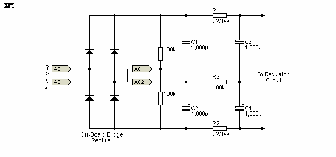
Figure 1A - Modified Rectifier To Use 50-60V AC 48V Input
To use a single 50-60V winding, simply replace D1 and D2 with 100k resistors, link the AC1 and AC2 terminals, and apply the output from an external bridge rectifier as shown. Positive goes to the cathode connection of the D1 position (positive terminal of C1) and negative to the anode of the D2 connection (negative terminal of C2). The external bridge can be made easily on a small piece of Veroboard, or use a 1A bridge assembly if you prefer. Make absolutely sure that you get the polarity right - the filter caps and regulator will be destroyed if you get it wrong!
The next problem is how to actually send the phantom power to the microphone and not the mixer input circuits. The latter will not be impressed with 48V DC applied, and will most likely voice their displeasure by failing instantly. The standard value of 6.81k (0.1% tolerance) for phantom feed circuits can be reduced to 6.8k (a standard E12 series resistor value), and I suggest that using a multimeter to match the resistors to at least 0.1% is the easiest and cheapest alternative. Each pair of resistors should be matched to within 10 ohms (or less if possible) of each other for best results. This is better than 0.1%, and ensures that common mode performance is not compromised.
In case you were wondering about my claim that 10 ohms is better than 0.1%, a worst case pair of 0.1% 6.81k resistors could have a difference of 13.62 ohms - one resistor at the maximum positive tolerance, and the other at maximum negative tolerance. Fairly obviously, the closer the match the better, and the multimeter used does not have to be absolutely accurate, since you are measuring for a difference rather than an absolute resistance value. If your multimeter refuses to measure to the number of digits needed, see the appendix for an alternative method you can use.
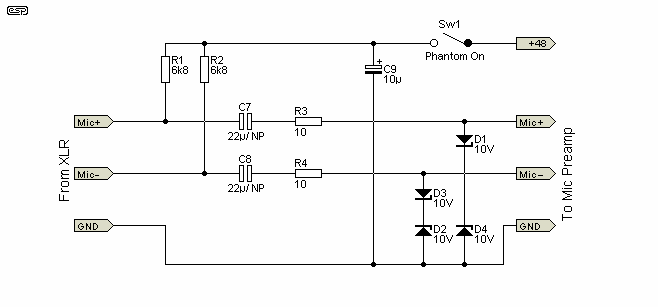
Figure 2 shows the basic phantom powering scheme. Only one channel is shown - subsequent channels are identical, up to a typical maximum of 10 (20 at a pinch) for a single supply module.
Although shown using bipolar electrolytic caps, some constructors will no doubt want to use something 'better', but polyester or similar caps at those values will be very large! Assuming a mic circuit input impedance of 1.2k (fairly typical), the two 22uF caps as shown will give a -3dB frequency of 12Hz - this is needed to get flat response to 20Hz. Naturally, if the lowest frequency you need is higher, then lower capacitance is acceptable. Likewise, if the mic preamp input impedance is higher than 1.2k, less capacitance can also be used.
It is worth noting that many mixers use polarised electrolytics at the inputs of phantom power circuits. While this is quite ok while phantom power is applied, the caps will be unbiased when phantom power is not being used. This is usually alright, provided the instantaneous voltage across the caps never exceeds 1V. Use of unpolarised caps may produce audible distortion or colouration in some cases. For a "cost no object" design, use 10uF/50V (or higher) polyester caps, enclosed in their own shielding can. These can be wired into the PCB without too much difficulty. If you choose to use polarised electrolytic caps for C1 and C2, the positive end must face the mic inputs (connected to the 6.8k resistors).

Figure 2 - Phantom Powering Circuit (P96B PCB)
Zener diodes must be used as shown to limit the maximum voltage applied to the mic input circuits. The worst possible scenario is when a mic lead is connected to a mic while phantom power is on. The cable is effectively a capacitor, and the sudden discharge of the cable and coupling caps can create a high current through the zeners, which must be capable of withstanding the surge without failure. Fortunately, 1W zeners are rugged enough to take it, and this is almost an industry standard circuit. Maximum surge current for 1W 10V zeners is typically around 450mA, and this is unlikely to be exceeded in practice. 10V zeners are specified because it is virtually impossible for any microphone to exceed that level, and the mic preamp will clip well before you achieve the 7V RMS input voltage limit imposed by the zeners. In addition, 10V zeners have a higher current capacity than higher voltages for an additional safety margin. The 10 ohm series resistors will have little or no influence on input level or noise, and help to limit the peak zener current.
Some mixers boast a 'silent' phantom switch to alleviate the typical loud BANG through the mixer when phantom power is turned on or off. The phantom distribution PCB (2 channels) has this feature, but it is not shown here.
Somewhat naturally, I suggest the PCBs be used, as this makes construction very easy. The PCBs both measure only 64mm x 38mm (2.5" x 1.5"), so will be easy to retrofit into all but the most compact mixer. Where there is just no space at all, an external box can house the regulator and distribution board(s).
If you don't wish to buy the PCBs, you may use Veroboard, but unless great care is taken with the earthing arrangements, noise will almost certainly be worse than quoted. All electrolytic caps should be rated at 50V or higher (NOTE: C5 in Figure 1 must be rated at 63V!). A standard 50V ceramic is recommended for C7, which is used to ensure that the regulator does not oscillate. Not shown (or needed) are film caps in parallel with the electrolytics - if you wanted to, these may be added, but with the filtering shown high frequency noise should be non-existent.
The power transformer does not need to be anything too fancy, but I suggest a separate box for it to minimise hum and noise. Typically, a 20VA 15-0-15V (or a multitap transformer with a 30V connection) will be more than enough. These are available readily in Australia, but I can't speak for the rest of the world. If the worst comes to the worst, you can use a pair of single winding 15V transformers, with the windings in series to give 30V. I recommend a conventional 'EI' transformer if possible, as these have less capacitance between primary and secondary, and will allow less HF mains noise through.
 |
It is extremely important that the transformer is not used to power other supplies or equipment. The centre-tap must not be connected to anything, and needs to be insulated to prevent contact. The supply circuit uses the full 30V AC in a floating configuration, and connection to another supply or rectifier will cause a short on the winding. |
Q1 on the power supply (Figure 1) must be fitted with a heatsink, and worst case power dissipation will be around 5W. This may not seem like a great deal, but a 10°C/W heatsink (typical of a large PCB mount type) will get to 50°C above ambient temperature (i.e. too hot!) at 200mA output.
At 100mA load, this is reduced to about 3W, which is a little more manageable. Even so, there is no such thing as a heatsink that is too big, so I suggest that you use the largest one that you can. Forced air (fan) cooling will not be necessary.
The PCB is laid out such that the power transistor can be attached directly to the chassis if desired (using insulating washers and heatsink compound, of course), and this alleviates the need for a separate heatsink. For only one or two phantom powered mics, a heatsink is not essential, but a small one is cheap insurance. In this case, R1 and R2 in Figure 1 may be increased in value, and this will provide even better filtering. 100 ohms will be more than satisfactory for a two microphone system.
The age old methods are sometimes the best. A Wheatstone Bridge used to be the standard method of accurately measuring resistance, inductance and capacitance, but new digital instruments have taken over. This is a shame (I think), because the old methods actually taught you something as you used them - not the case with any digital instrument.
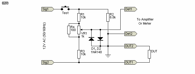
A Wheatstone Bridge is easy to set up, and while it is not especially accurate in absolute terms, it can be made extremely sensitive to variations between components. Using a power supply, 9V battery (or even better, a 12V AC voltage from a transformer), the circuit shown in Figure 3 will resolve a difference of 1 ohm easily with a suitable test setup. A difference of 10 ohms will give a 4.38mV output signal from a 12V input.

Figure 3 - Wheatstone Bridge
Because the bridge circuit does not care if you use AC or DC, an amplifier can be used to detect the null, and it can be made almost unbelievably sensitive. In use, wire up the circuit as shown, and use a meter or amplifier and headphones (or speaker) to monitor the difference signal. Be warned - the amp input signal will be 6V RMS (for a 12V input) with the DUT (Device Under Test) removed, unless D1 and D2 are installed as shown.
You will have a number of 6.8k resistors to hand, all of the same nominal value but having normal (1%) tolerance. Install one as a test resistor, and adjust VR1 for a complete null (no signal). That is now your reference resistor. One by one, connect the remaining resistors into the circuit, and aim for an output signal of less than 4mV - do not re-adjust VR1. Hopefully, you will find a number of resistors that are close to the reference you chose - if not, simply choose a different resistor to use as the reference, and re-balance the bridge. Repeat these tests until you find as many resistor pairs as you need - each pair will now be very closely matched if you did the test and selection properly.
The signal input (applied unsurprisingly to Sig1 and Sig2) must be floating if you use an amp for monitoring, since one side of the amp input will be earthed as shown. A 50 or 60Hz 12V transformer is fine for this. Press the TEST button only when the DUT is securely attached, or the output will be very loud indeed. Connect a pair of diodes across the Monitor terminals - in parallel and opposite polarity. This will keep the maximum level down to something more sensible if the Test button is pressed when nothing is attached to the DUT terminals.
The Wheatstone Bridge is a very useful device that you can use for comparing resistors, capacitors and inductors - actually, you can match any passive components and even complete networks by this means. Wheatstone bridges are also used for precision temperature measurement, strain gauges (used to test mechanical movement in structures) and have many other uses.
 Main Index
 Projects Index