
|
| Elliott Sound Products | Project 30c |
Stage 3 shows the power supplies for the mixer. The supply needs to be quite substantial, due to the high current drain of a complete 36-4-2 mixer. I will have to leave it up to individual constructors to determine if they really need this much power, or can survive on a lesser version, but if the full power supply is built, it will allow for expansion later. The phantom supply is designed to provide 150mA at 48V, which should be more than enough for any application.
Also included is the headphone power amp (two needed for stereo), with the mixing and selection coming in the next section.
The mixer requires +/- 15V at up to 4A for a fully configured system. Since this is well outside the capability of a 3 terminal regulator, I have used booster transistors (a quite common thing to do) to increase the available current. The regulation is completely controlled by the 3-terminal regulator, and the transistor simply boosts the current. Dissipation in the transistor will be quite high, so good heatsinking is essential.
Using a 20V (AC) transformer gives about 28V before regulation, allowing plenty of margin for low supply conditions, but increases the transistor dissipation. At 4 Amps output, worst case transistor power will be over 40W, so the heatsink will need to be rated at less than 1°C /W to ensure that the transistors remain well within their safe operating area.

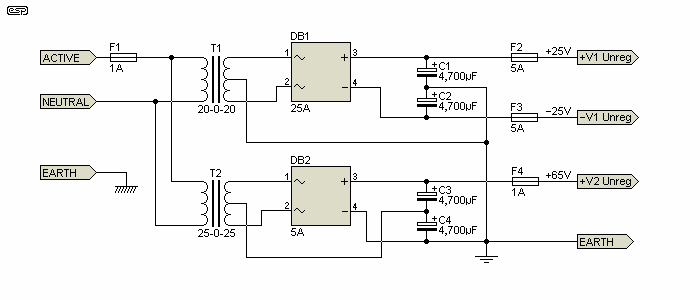
Figure 1 - Transformers and Rectifiers
The transformers, rectifiers and capacitor banks in Figure 1 are also shown in the previous section, and the circuit is included here for completeness. As indicated in the last section, T1 needs to be at least 150VA, and T2 can be a smaller (and cheaper) 20VA. The bridge rectifiers need to be more substantial than you might think, because of the sustained current. I suggest that a 25A bridge is used for the +/- 15V supplies, and a 5A bridge for the 48V supply.

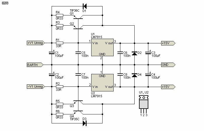
Figure 2 - 15V Regulators
Figure 2 shows the regulators for the +/- 15V supplies. DC from the rectifier is supplied to the 3 terminal regulator IC via a 33 Ohm resistor. When the current exceeds about 20mA, the power transistor will turn on, and the IC will ensure that the DC output is kept exactly to the specified voltage. This ensures that the regulator IC is operating at a low power (requiring only a small PCB mount heatsink), and will remain cool.
Typically at an output current of 4A, the transistors will require about 200mA of base current, which must be passed by the regulator. The maximum regulator power is therefore about 2.6W - a 10°C/W heatsink is therefore sufficient (but only just - use a bigger one if possible). Make sure that each regulator is on its own heatsink, and uses no insulating washer for maximum heat transfer. Use heatsink compound between regulator and heatsink. Do not mount the regulators on the main heatsinks - these will operate at a higher temperature than the small individual heatsinks.
The power transistors will be operating at a sustained high power level, and must have substantial heatsinks. Dissipation will be in the order of 25W each at 4A, which means that the temperature must be kept below 100 degrees. Using the arrangement shown with parallel transistors, this is easily achieved, and will require a heatsink with 1.0 degree C/W for each transistor pair. By this means, a smaller heatsink may be able to be used than would otherwise be the case, since the dissipation of each transistor is reduced and the junction to heatsink thermal resistance is also reduced. The heatsink will still run at quite a high temperature, and should be mounted where it cannot be touched, but still has good airflow. I recommend either the biggest heatsink you can accommodate, and/or use a fan to assist cooling. The transistors shown are the minimum specification you can use - preferably, use higher power transistors. The TIP35C and TIP36C devices suggested are very robust, but higher power transistors certainly won't hurt anything. You may want to consider fan cooling if the heatsinks get hot in use.
The diodes (1N4001 or equivalent) around the circuit ensure that disconnection of the DC input will not damage the regulator. Note that the +ve and -ve regulators have different pinouts - do not get them mixed up, or they will be damaged or destroyed when power is applied. Please check the datasheet to make sure that you get the IC connections right!
Note also that there is no easy way to provide short circuit protection to this configuration, and care is needed to make certain that a short cannot occur. For this reason, I suggest that the transformers, rectifiers and capacitors are housed in a separate case (typically floor mounting), and that the DC output be fused as shown in Figure 1.
The regulators can be housed in the main mixer, keeping all input wiring well away from mix buses. The DC input will have ripple at high current, and if allowed near a bus will inject hum into the system. The 100uF capacitors should keep the circuit stable at all operating levels, and can be bypassed with 100nF caps if desired.
Although high voltage 3 terminal regulators are available, they are not readily available to most constructors. I have therefore elected to use a discrete design, which although quite simple will give very good results. The regulation does not need to be any better than about 1 to 2% from no-load to full-load, but noise (ripple) must be kept to a minimum.

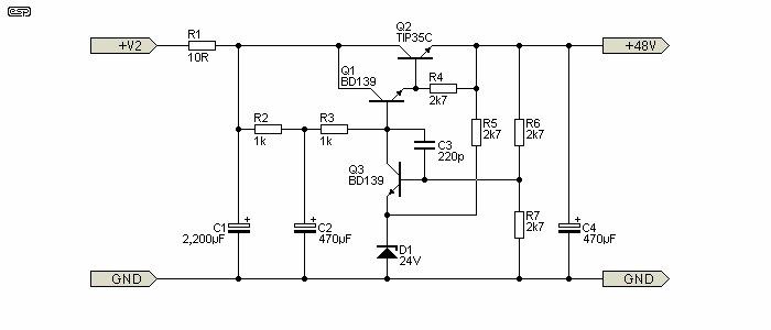
Figure 3 - 48V Phantom Supply
At full load, the power in the series pass transistor (Q2) will be only about 1.8W, so a massive heatsink will not be necessary. A small 10 degree/W sink will ensure that the maximum temperature rise is less than 20°C, which is a generous safety margin. Q1 should also have a heatsink, as its dissipation will be about 400mW at no load. A simple flag heatsink will suffice.
Using a resistor filter is awful for regulation, but gives good ripple rejection, and is simple and cheap. A 10 Ohm resistor and 2200uF capacitor will have a very profound effect on ripple applied to the regulator, which simplifies its design. This simple addition reduces ripple to about 1/30th of that without the filter, so is well worth the small extra outlay for the resistor and cap. The circuit shown has better than 80dB of ripple rejection, so the output will typically have less than 20uV of hum. As this is applied as common mode to the microphone leads, the overall rejection will be found to be more than adequate. The circuit in Figure 3 has a regulation of better than 2% from no-load to full-load, which is quite acceptable.
Note that the P48 supply is not adjustable, and the voltage may be a little high or lower than 48V. If you wish to be able to adjust the voltage, replace R7 with a 1k5 resistor, and include a 2k trimpot in series with it. Adjust the added trimpot to give an output of 48.5V with no load. This will fall under full load conditions (140mA for 20 channels in use) to about 47.8V or so, indicating a regulation of about 1.4%.
 Click on the PCB image to see Project 96 - a (slightly) different version of the phantom feed power supply. PCBs are available, but may not provide the current needed for a large console.
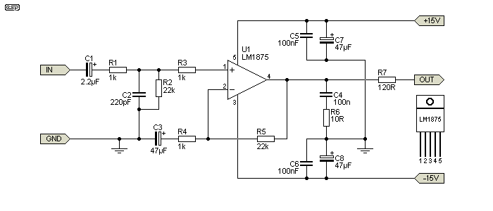
The headphone amps are based on the LM1875 power opamp. This is capable of 25W, but in this application is deliberately restricted to 50mW into 8 Ohm 'phones. This is more than enough, but at least ensures that the amp will never clip at any listening level that is even remotely sensible. If more level is needed, R7 can be reduced (56 ohms is a sensible minimum). Duplicate R7 if more then one headphone output is needed, but note that they will be at the same level. Do not use more than 4 headphone feeds, as the current drain on the ±15V supplies will become excessive.

Figure 4 - Headphone Power Amp
The units can be assembled on Veroboard (but see below first - there is a PCB available for this power amp). The 100nF caps in the supply lines need to be as close to the power pins as possible. Some care is needed with the layout to keep input circuits well away from the output, as these devices have wide bandwidth and will oscillate if construction is unsuitable.
R7 should be at least 1W, and limits the power to the headphones. Two circuits will be needed for stereo 'phones, and the ICs must be mounted on a suitable heatsink. Make sure that the power rails for these amps are taken straight back to the regulator outputs, and not connected to the main supply buses for the mixer modules. Relatively high peak currents with unpleasant waveforms may otherwise introduce distortion into the completed unit.
The Pre-Fade Listen and headphone selection and mixing circuitry will be published in the next installment.
 Click on the PCB image to see Project 72 - almost identical to the above, and PCBs are available.
Headphone selection and pre-fade listen amps. Also the talkback mic input, phono and auxiliary input modules, metering circuits, and a few miscellaneous other bits.
There will also be an overall layout diagram, and a picture of what the panel of a complete system might look like. This in itself should be interesting, as I have no idea yet how I am going to make such a large drawing (and keep the file size down to something sensible).
| Index | Stage 1 | Stage 2 | Stage 3 | Stage 4 |
 Main Index
 Projects Index