
|
|
| Elliott Sound Products | Project 72 |
 Please Note: PCBs are available for the latest revision of this project. Click the image for details.
There are many instances where a simple and reliable power amplifier is needed - rear and centre channel speakers for surround-sound, beefing up the PC speakers, low powered tweeter amplifier, etc. For those who want to build their own 'Gainclone' amplifier, this will certainly do the job. 
This project (unlike most of the others, but in a similar vein to Project 19) is based almost directly on the typical application circuit in the National Semiconductor specification sheet. You can also use the TDA2050 (from SGS-Thompson), which has almost identical performance and (remarkably) the same pinouts! As it turns out, the amp in the NS application circuit is pretty good, as is the (very similar) one from SGS. The amp is also very simple to build - if you have a PCB! These ICs are a cow to wire on Veroboard - it is possible, but results are unpredictable.
Note that the TO-220 SGS-Thomson (now STMicroelectronics or 'ST') TDA-series IC power amps are now discontinued, leaving only the LM1875 as an 'official' option. There are many on-line sellers offering the TDA series of IC power amps, but they are not official distributors and the devices offered are probably not genuine. This doesn't necessarily mean they won't perform as expected, but it does mean that you can't be certain of their provenance.
Figure 1 shows the schematic - this is almost the same as in the application note (redrawn), and with added (optional) RF protection at the input (R1 and C2). Note that the speaker must return to the central 'star' earth (ground) point at the junction of the power supply filter caps. If connected to the amplifier's earth bus, you will get oscillation and/or poor distortion performance. R3 is shown as 1k, but this can be reduced to no less than 220 ohms. It's there to help suppress RF interference.
Figure 1 - LM1875 / TDA2050 Power Amplifier Circuit Diagram (One Channel)
Voltage gain is 27dB as shown, but this can be changed by using a different value resistor for the feedback path (R4, currently 1k). Increasing the value of R4 reduces gain and vice versa. The amplifier must not be operated at any gain less than 10 (20dB) as set by R4 and R5, as it will oscillate. Gain above 33dB (R4 = 470Ω) is not recommended as the distortion will increase. In some cases, an inductor may be needed in series with the output to prevent instability with capacitive loads (10 turns of 0.5mm wire wound around a 10 Ohm 1W resistor). The most common capacitive load is the speaker cable itself, and 'audiophile' leads are usually much worse than standard grade cables in this respect.
The 10 Ohm resistor (R6) should be a 1W or 0.5W type, and all others should be 1/4W 1% metal film (as I always recommend). All electrolytic capacitors should be rated at 50V if at all possible, and the 100nF (0.1µF) caps for the supplies should be as close as possible to the IC to prevent oscillation. C1 should be a bipolar (non-polarised) electrolytic, or may be plastic film if you prefer. A polarised electro will also be perfectly alright, because any DC voltage present will be well below 10mV.
The supply voltage should be no more than ±25 Volts at full load, which will let this little amp provide a maximum of 25 Watts (rated minimum output at 25°C). To enable maximum power, it is important to get the lowest possible case to heatsink thermal resistance. This will be achieved by mounting with no insulating mica washer, but be warned that the heatsink will be at the -ve supply voltage and will have to be insulated from the chassis. For more info on reducing thermal resistance, read the article on the design of heatsinks - the same principles can be applied to ICs - even running in parallel. I haven't tried it with this unit, but it is possible by using a low resistance in series with the outputs to balance the load. I do not suggest that you even attempt parallel operation unless you are very sure of the requirements and your abilities!
Note that the supply voltage must not exceed ±30V at any time - this is the absolute maximum voltage rating for the LM1875. The TDA2050 is rated for a maximum of ±25V. I recommend that neither amp should be used with a nominal supply voltage greater than ±25V, and preferably a little less.

Figure 2 - IC Pinouts
Figure 2 shows the pinouts for the LM1875, and it should be noted that the pins on this device are staggered to allow adequate sized PCB tracks to be run to the IC pins. The same pinouts are used for the ST devices (TDA2050 and lower power versions, such as the TDA2030 and TDA2040). Most of the TDA series are considered obsolete - they are no longer available from the major suppliers, so you have to resort to other suppliers who may or may not be offering the genuine article.

Note: If you can get the TDA20xx ICs, you will need to consult the datasheet to determine the maximum voltage you can use. For example, the TDA2030 is specified to run from a maximum supply of ±18V, with ±16V or so being safer. The TDA2030A is rated for ±22V, and the TDA2040 for ±20V. Unfortunately, some of these voltage require an odd transformer voltage for the power supply, but you might (just) get away with using a transformer with 12-0-12V secondaries. The unloaded supply voltage may be slightly more than the stated maximum, but I have tried it and the ICs survived just fine. With ±16V, the power output will be around 12W into 8 ohms, or 16W into 4 ohms.
The PCB for this amp is for a stereo amplifier and is single sided. The entire stereo board is 82mm × 37mm (i.e. really small). The heatsink needs to be bigger than you might expect, largely because of the relatively high thermal resistance of the TO-220 case. National (now Texas Instruments) recommends that the heatsink should be no smaller than 1.2°C/ Watt (it is actually suggested that the heatsink be 0.6°C/ W, but this is a very large heatsink, and is not necessary for normal audio into reasonably well behaved loads.
Never operate these ICs with no heatsink, even without any load connected. The quiescent dissipation will cause them to overheat very quickly, and may damage the internal circuitry.
Output power of the LM1875 is rated at 25W per channel, and with music signals you will probably be able to get that peak power easily enough, but 20W into an 8 ohm load is more realistic. Refer to the data sheet for the full specification on the IC. Note that the TDA2050 spec sheet claims 32W (at 10% distortion, which is intolerable), but this is overly optimistic and cannot be achieved in practice. Be careful when looking at power ratings for any of these ICs - they do not necessarily reflect reality.
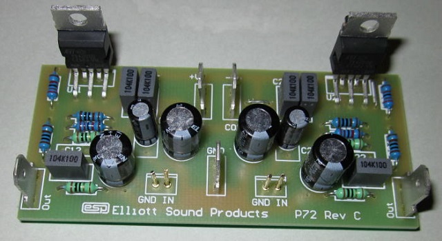
Photo of Completed Amp (Without Heatsink)
The sound quality is very good - as I said at the beginning, I would not call it audiophile hi-fi (but then again - I might, with caveats), and provided the amp is never allowed to clip it sounds excellent. Because of the overload protection (which I have never liked much in any form), this amp provides somewhat nastier artifacts as it clips than most discrete amplifiers.
For those who think an incredibly short feedback path length is actually important (hint: it's not), a surface mount resistor can be used for R5, either soldered directly to the leads (pins 2 and 4) or the pads on the copper side of the board. This will provide a feedback path of less than 20mm in total, and could be made less than 10mm (at the risk of damaging the IC with excess heat). IMO attempting this is just silly, and you'll never hear the difference in a blind test. It's extremely doubtful that you'll be able to even measure any difference, and the IC isn't designed for microwave operation (where a short feedback path is actually important).
This amp is ideal for Hi-Fi PC speakers, and could also be used as a midrange and/or tweeter amp in a tri-amped system - there are a lot of possibilities, so I will leave it to you to come up with more.
A suitable power supply diagram is shown below. This is adequate for as many amplifiers as needed, simply by increasing the size of the transformer. A 15-0-15 volt transformer is ideal, providing a conservative (and safe) ±21V. To get the maximum available power, use an 18-0-18V transformer, which provides ±25V. The lower supply voltage can be used if you don't need the maximum power, and you don't actually build a small amp to get a lot of power. Less than ±10V is not recommended, as this is approaching the minimum allowable for the ICs.
Remember that if you use any of the TDA series ICs, the power supply voltages are lower, so a transformer with the appropriate voltages has to be selected. Make sure that the absolute maximum supply voltage is not exceeded or the IC will be damaged.

WARNING: In some countries it may be required that mains wiring be performed by a qualified electrician - Do not attempt the power supply unless suitably qualified. Faulty or unsuitable mains wiring may result in death or serious injury. All mains wiring must use mains rated cable, segregated from input and low voltage wiring as required by local regulations.
Figure 3 - Power Supply
Although 4,700µF capacitors are shown, the amplifier will operate quite happily with less - I do not recommend anything less than 2,200µF for a pair of amps, and more than 10,000µF is probably being silly. The transformer rating is up to you. It can be less than 50VA for low power versions, and more than 150VA is completely unwarranted - the regulation improves with greater VA ratings, but the law of diminishing returns comes into play quite quickly.
Signal earth and mains earth should be tied together at a single common point, which will become the 'star' earthing point for the whole amplifier. This should be as close as possible to the common of the filter capacitors. The mains earth must connect to the chassis to prevent electric shock in case of a transformer 'meltdown'. While it is recommended that the signal and mains earth (ground) connections should be joined, this may result in an earth (ground) loop causing hum. You can use a 'loop breaker' as described in Project 04.
 Main Index
Projects Index Main Index
Projects Index |