
|
|
| Elliott Sound Products | Beginners' Guide to Transformers - Part 2 |

 Main Index
Articles Index Main Index
Articles Index
|
For those brave souls who have ploughed their way through the first section - I commend you! As you have discovered, transformers are not simple after all, but they are probably far more versatile than you ever imagined. They are, however, real world devices, and as such are prey to the failings of all real components - they are imperfect.
This section will concentrate a little more on the losses and calculations involved in transformer design, as well as explain in more detail where different core styles are to be preferred over others. Again, it is impossible to cover all the possibilities, but the information here will get you well on your way to a full understanding of the subject.
The first topic may seem obvious, but based on the e-mails I get, this is not the case. Transformers can have multiple windings, and these can be on the primary or secondary. Windings can be interconnected to do exciting and different things, but from a safety perspective it is imperative that primary and secondary windings are kept segregated.
There are several references to 'shorted turns' within this article. If any two turns of a winding short to each other, the current flow is limited only by the DC resistance of the shorted section of the winding. The current flow can be enormous, and with even one shorted turn, the transformer is no longer serviceable and must be discarded or rewound. No shield or other conductive material may be wrapped around the winding and joined, as this creates a shorted turn capable of possibly hundreds of amperes. The exception to this is the magnetic shield sometimes used with E-I laminated transformers, but this is wrapped around the entire transformer (outside the core), and is not considered as a 'turn' as it is not in the winding window with the primary and secondary.
It is also worth noting that a transformer behaves quite differently depending upon whether it is driven from a voltage source (i.e. very low impedance, such as a transistor amp or the mains) or a current source or intermediate impedance. This will be covered in a little more detail further on in this article.
Three things that you need to keep in mind - always ...
Note: This is the practical case, assuming normal usage of the transformer. A theoretical 'ideal' transformer having zero winding resistance will have constant flux, regardless of load - provided the input voltage is constant. Since the real world has real-world transformers, the flux decreases slightly with load due to the voltage lost across the transformer's primary winding. This is explained in more detail below.
Before reusing any transformer - especially if designed for a different purpose, voltage or frequency - you need to check that it will not draw excessive magnetising current. Worst case is with no load, and the current should be measured and the temperature monitored for long enough to be certain that the transformer does not get so hot that it's uncomfortable to hold. If the idle temperature rise is more than about 25°C the transformer should not be used. Bear in mind that some small transformers run rather hot all the time, so on occasion you may have to make a value judgement based on experience.
Many transformers are supplied with two (or more) secondaries. In many cases, the data sheet will indicate that the windings may be connected in parallel or series. For example, a toroidal transformer may be rated at 2 x 25V at 5A (250VA). With the windings in parallel, the available current is 10A, but only for a single voltage of 25V AC. Connect the windings in series, and you get 50V at 5A, or by referencing the centre tap to earth, the familiar 25-0-25 designation.
Figure 8.1 - Windings in Series and Parallel
There are some rules that apply to winding interconnections - if you break them, you may break your transformer as well. Note the dots on the windings - this is the traditional way to identify the start of a winding, so that the phase may be determined.
Autotransformers are covered in Section 19 below. These are a special case of windings in series, and are commonly used to obtain a reduced voltage with the highest possible efficiency and lowest cost.
Antiphase wiring will not harm a transformer when wired in series (although the zero volts output for equal windings is somewhat limited in usefulness). Parallel antiphase connection will destroy the transformer unless the fuse blows - which it will do mightily. Always use a fuse when testing, as a simple mistake can be rather costly without some form of protection for the transformer and house wiring!
Windings may be connected in series regardless of voltage. The maximum current available is the rating specified for the lowest current winding. Windings may be connected so as to increase or decrease the final voltage. For example, dual 25V windings may be connected so as to produce 50V or zero volts - although the latter is not generally useful :-)
When windings are connected in phase the voltages add together, and if connected out of phase, they subtract. A 50V, 1 amp winding and a 10V 5 amp winding may therefore be connected to provide any of the following ...
The above example was used purely for the sake of example (such a transformer would not be useful for most of us), but the principle applies for all voltages and currents. Series connections are sometimes used in the primaries as well, mainly for equipment destined for the world market. There are several common mains supply voltages, and primary windings are connected in various combinations of series and parallel to accommodate all the variants.
Parallel connection of transformer windings is permitted in one case only - the windings must have exactly the same voltage output, and must be connected in phase. Different current capacities are not a problem, but it is rare to find a transformer with two windings of the same voltage but different current ratings.
Even a 1V difference between winding voltages will cause big problems. A typical winding resistance for a 5A winding might be 0.25 ohm. Should two such windings be connected in parallel, having a voltage difference of 1V, there will be a circulating current limited only by the resistances of the windings. For our example, the total winding resistance is 0.5 ohm, so a circulating current of 2A will flow between the windings, and this is completely wasted power. The transformer will get unexpectedly hot, and the maximum current available is reduced by the value of the circulating current.
Should the windings be connected out of phase, the circulating current will be possibly 100A or more, until the transformer melts or the fuse blows. The latter is generally to be preferred.
The transformer manufacturer's specifications will indicate if parallel operation is permitted. If you are unsure, measure the voltages carefully, and avoid parallel connection if the voltages differ by more than a couple of hundred millivolts. There will always be a difference, and only the manufacturer's winding tolerances can predict what it will be. With toroidal transformers, the windings are often bifilar, meaning that the two windings are wound onto the transformer core simultaneously. The tolerance of such windings is normally very good, and should cause no problems.
In Section 1, I described a very basic push-pull valve output stage. Now it is time to examine this a little more closely. We shall use the same voltages as were obtained in the basic description of Section 1 - an RMS voltage of 707V. It must be said that the following is not intended to be an accurate representation of valves, as the losses in real life are somewhat higher than indicated here. This is for example only. We shall also take the (typical) losses as 10%, and adjust the secondary impedance accordingly.
A valve (tube) amplifier is required to drive an 8 ohm loudspeaker. The primary impedance (called the Plate-Plate impedance for a push-pull amplifier) is 6,000 Ohms, and the supply voltage is 600V. Allowing for losses of 100V across each valve, the maximum voltage swing on the plates (anodes) of the valves is 1kV p-p (or effectively 2kV peak to peak on the transformer primary). What is the output power?
Secondary impedance will be 7.2 ohms, based on the 10% loss ...
Zs = 8 / 1.1 = 7.2 ohms
The impedance ratio is calculated first ...
Z = 6,000 / 7.2 = 833
The turns ratio may now be determined
N = √833 = 28.8 (29:1)
The voltage ratio is the same as the turns ratio, so the peak to peak voltage to the speaker is
Vs (p-p) = Vp / N = 2,000 / 29 = 69V
To convert this to RMS ...
Vp = 1/2 Vp-p = 34.5V
RMS = peak × 0.707 = 24V
Power is therefore 24² / 8 = 72W
Notice that at each calculation, the figures were rounded to the closest (or next lowest) whole number. This was for convenience, but the way I did it also gives a conservative rating that is more likely to be met in practice.
Ouch! Sorry, that was a bit nasty for this time of day  .
.
A bit nasty or not, it is a reasonable representation of the reality of an output transformer design, but naturally real (as opposed to my 'invented' figures) will be substituted. Typically the losses across the output valves will often be far greater than indicated here. but that depends on the valves used (and the topology - triodes behave very differently from pentodes or tetrodes).
Just to complete this section and to put the above into perspective, I have included a few figures (taken from the 1972 Miniwatt Technical Data manual) for the EL34/ 6CA7 power pentode - one of the world's all-time favourite output valves.
| Class | Mode 1 | Plate Volts |
Plate Current | Screen Volts | Screen Current |
Grid Bias | Load Impedance | Power Output |
Comments |
| Class-A | S-E | 250 | 100 | 265 | 15 | -13V | 2,000 | 11W | Plate supply = 265V, THD 2 10% |
| Class-AB | P-P | 375 | 2 x 75 3 2 x 95 |
365 | 2 x 11.5 2 x 22.5 | -19V | 3,400 (p-p) 4 | 35W | Cathode bias resistor 130 ohms, common screen resistor, 470 ohms, THD 5% |
| Class-B | P-P | 775 | 2 x 25 2 x 91 |
400 | 2 x 3.0 2 x 19 | -39V | 11,000 (p-p) | 100W | Plate supply, 800V, THD 5% |
| Class-A (Triode) | S-E | 375 | 70 | - | - | -25V | 3,000 | 6W | Cathode bias resistor 370 ohms, Screen tied to plate, 400V plate supply, THD 8% |
| Class-AB (Triode) | P-P | 400 | 2 x 65 2 x 71 |
- | - | -28V | 5,000 (p-p) | 16W | Screen tied to plate, Cathode bias resistor 220 ohms, THD 3% |
1 S-E: Single Ended, P-P: Push-Pull 2 THD - Total Harmonic Distortion (this is for the valves only, and does not include transformer distortion) 3 First figure is no load, second figure is full power 4 p-p: Plate to Plate impedance
As can be seen quite readily, the distortion of the S-E configurations is much worse than the push-pull versions. Not only that, but (to maintain relevance :-) the transformers are larger and harder to design, and even then will be worse than their push-pull counterparts. In the maximum efficiency configuration, power output is 100W, and distortion is still lower than for either of the single ended configurations. The losses across the output valve in this mode are about 58V, but are considerably higher for any of the cathode biased versions - as one might expect.
This will be revisited in another article on the design of valve amplifiers.
It is very important that the core does not saturate (see below), since there will be no continuous sinusoidal variation of flux, greatly reduced back EMF, and excessive current will be drawn - especially at no load. The final design of any transformer is a huge compromise, and there is a fine line between a transformer that will give acceptable regulation and one that gets too hot to touch at no load.
Somewhat surprisingly, the flux density in the core actually decreases with increased load current drawn from the secondary. Even though the primary is drawing more current, this is transferred to the secondary and thence the load - it does not cause the flux density to increase. The flux density decreases largely due to primary resistance, which causes the effective primary voltage to decrease. Any voltage lost to resistance (remember Ohm's law?) is voltage that is 'lost' to the transformer, and serves no function in the transformation process. It does cause the transformer to get hot (or hotter) than at no load. See the next section for more details on this.
Also, the normal variation of mains voltage must be allowed for. A transformer running at the very limit of saturation at nominal supply voltage will overheat if the mains is at the upper (normal) limit. A transformer that is designed to run at the limit will have superior regulation compared to a more conservative design, but this is of little consequence if it fails in normal use due to overheating.
For audio transformers, there are even more compromises.
As discussed earlier, a transformer is a real component, and therefore has losses. These are divided into two primary types, but there are other 'hidden' losses as well. All losses reduce efficiency, and affect frequency response. The low frequency limit is determined by the primary inductance, and this is proportional to the area (and consequent mass) of the transformer core. High frequency losses are caused by eddy currents in the core (see below), and by leakage inductance and winding capacitances.
None of these can be eliminated, but by careful selection of core material, winding style and operational limits, they can be reduced to the point where the transformer is capable of doing the job required of it.
Core losses are partly the result of the magnetising current, which must keep forcing the magnetic field in the core to reverse in sympathy with the applied signal. Because the direction of flux is constantly changing, the transformer core is subject to a phenomenon called hysteresis, shown in Figure 11.1
Figure 11.1 - The Hysteresis Loop
When the magnetomotive force is reversed in a magnetic material, the residual magnetism (remanence - also known as remnance in some cases) in the core tries to remain in its previous state until the applied flux is too great (coercivity). It will then reverse, and the same situation will occur twice for each cycle of applied AC. The power required to force the flux to change direction is the hysteresis loss, which although usually small, is still significant. I am not about to go into great detail on this, but a Web search will no doubt reveal more information than you will ever need.

Figure 11.2 - B-H Curve
As can be seen from the two magnetic field drawings, the flux density (B) is dependent upon the applied magnetic field strength (H). For the example shown, the 'knee' of the curve coincides with the point where permeability starts to fall. Above this, a progressively larger change in the magnetic field is required to increase the flux density. This is saturation, and most transformers will be designed to operate at or below the knee. Above the knee is dangerous, as a small increase in applied voltage will not produce the required increase in back EMF, and the primary current will increase disproportionately to the rise in voltage. In other words, the transformer will be too sensitive to applied voltage, and will possibly self destruct if the mains voltage were even slightly higher than normal. If such a transformer is wound for 60Hz but used at 50Hz, failure is inevitable.
Figure 11.3 - Cutaway View of a Transformer
The transformer shown is a 'split bobbin' type, having separate sections on the former for the primary and secondary windings. This reduces the capacitance between windings, and also provides a safety barrier between the primary and secondary. For some applications, this is the only winding method that meets safety standards. It is also very simple to add an electrostatic shield between the windings - a flat plate of thin metal is cut so that it can be slipped over the bobbin, and the ends are insulated so that it does not create a shorted turn. This is connected to earth, and prevents noise from being capacitively coupled between windings. The shield would logically be placed on the secondary side of the bobbin divider for safety.
In addition, there are so-called 'eddy current' losses. These are small circulating currents within the magnetic core, as shown (exaggerated) in Figure 11.4, and these cause the core material itself to get hot. Each of these eddy current loops acts as a tiny shorted turn to the transformer, and to reduce the effect, the core is laminated - i.e. made from thin sheets of steel, insulated from each other. The thinner the laminations, the smaller are the eddy current losses, but they will never be eliminated. Eddy current losses increase with frequency, requiring different techniques for high frequency operation, and are the major contributor to the iron losses in any transformer.
Figure 11.4 - Eddy Currents in Laminations
The eddy currents are shown for three lamination thicknesses. Although not shown (for the sake of clarity), the current loops are constantly overlapping, and are effectively infinite in number. The thick laminations allow the loops to be larger, and therefore the lamination section is cut by more magnetic 'lines' of force, so the currents (and losses) are larger. For high frequencies (above 10kHz), it is generally not possible to make laminations thin enough to prevent the losses from becoming excessive, and ferrite materials are preferred. These effectively have a huge number of incredibly small magnetic particles, all insulated from each other, and eddy current loops are very small indeed. Even so, ferrite materials are normally specified up to a few hundred kilo-Hertz for power applications before the losses become too great again.
Iron losses of both types are the primary source of losses in any transformer that is operating at no load or only light loading. At no load, the core flux density is at its maximum value for any given applied voltage / frequency combination. Power transformers are usually designed to operate below the knee of the saturation curve (this is essential with toroidal types), with sufficient safety margin to ensure that the core can never saturate.
Saturation involves a dramatic loss of permeability (and therefore inductance), and causes the primary current to rise disproportionately to an increase of voltage. Where one would hope for a nice sinusoidal current waveform with low distortion, significant current waveform distortion occurs once the core starts to saturate.
As a load is drawn from the secondary, the primary must supply more current, and this means that the resistance of the primary winding becomes significant. Any voltage 'lost' to winding resistance is effectively no longer part of the applied voltage, so core flux is reduced.
For example, if the primary resistance is 5 ohms and the loaded primary current is 2A at 230V, 10V is lost across the winding resistance, so the effective primary voltage is reduced to 220V. This reduces the magnetising current, but the effect is not linear. It depends a lot on how close to saturation the core operates with no load, and the difference may be anything from minimal to significant, depending on the design.
Following on from the previous point, the voltage lost to winding resistance is copper loss, and all such losses must be dissipated as heat. Consider the same transformer as above at idle, with 230V on the primary. The primary resistance may be in the order of 5 ohms (a transformer of around 300VA), and the idle current perhaps 20mA. The loss is determined by the normal power formula, and in this case is ...
P = I² × R = 0.02² × 5 = 2mW
V = R × I = 5 × 0.02 = 100mV
For all intents and purposes, the full 230V is applied to the primary. When the transformer is loaded, this changes. Let's assume 2A primary current and look at the figures again ...
P = I² × R = 2.00² × 5 = 20W
V = R × I = 5 × 1.00 = 10V
Now, the effective primary voltage is only 220V, because 10V is 'lost' due to winding resistance. Naturally, if the voltage is lower, the flux density must also be lower. The power lost in the primary must be dissipated as heat, so the transformer will start to get hot. Remember that there will be additional losses in the secondary that add to the heat that must be dissipated.
Minimising copper loss in both primary and secondary is essential, but there are limits to what can be achieved. These are imposed by the available space for the winding, and just how much copper the manufacturer can get into that space. Allowance must still be made for insulation and manufacturing tolerances.
You may see that in Figure 11.3 the windings are shown stacked directly on top of each other. Surely a more efficient winding can be made by making use of the 'valleys', minimising the winding height and allowing heavier windings. Ah, if only life were that simple! The windings are traditionally made from left to right, then right to left, so the turns in each layer are at a slight angle relative to the layer below or above. It is therefore not possible to utilise the inter-turn winding valleys properly, and if you were to wind a transformer based on the erroneous assumption that this would work, the finished winding would not fit into the window.
For the normal layered construction (i.e. primary closest to the core, and secondary over the top), we also have to allow for insulation between primary and secondary, and in some cases additional insulation is used between layers of larger transformers because of the large voltage difference between the outer limits of each winding. These are another set of compromises that must be made, all of which mean that the windings must be thinner than we might like, and thus the losses are increased.
Because any length of wire has resistance, there will always be winding resistance. The greater the resistance for a given current, the more power is dissipated as heat - this is a complete loss. At no load (provided saturation is avoided), there is virtually no loss, since the currents are low, but as secondary current increases, so too do the copper losses.
The current density allowable for the copper windings is a somewhat variable figure. Current density refers to the current in Amps per unit of wire area, for example 2.565A/mm² (a reference standard used in Australia and presumably elsewhere as well). Increasing the current density has a major effect - it causes the wire to get hotter for a given current. Side forces caused by the magnetic fields generated between each turn need to be considered in large power distribution transformers, especially under short-circuit conditions where the forces can be destructive. There is no such thing as a 'typical' current density, because different manufacturers use different design criteria. In general, it's better to keep current density below 3.0A/mm² and 2.5A/mm² is even better. Naturally, a lower current density means that the transformer is larger and heavier than one operated at a high density, and ultimately it's all a trade-off against temperature rise and cost.
For many transformers used in audio, the current density can often be expected to be somewhat higher than one might prefer. This is because exceptionally high efficiency is not needed, and the demand from normal music programme material has a rather low average value. As a result, transformers for power amplifiers (for example) are rarely operated at continuous full load - they are more likely to be run with short term overloads, but at perhaps 50% full load on a long-term average basis when operated at the onset of clipping with 'typical' programme material.
I took a few measurements on transformers I have to hand, and found that with toroidals in particular, there is a common trend. The current density of the primary is comparatively low, averaging around 2.1A/ mm², while the secondaries all used a much higher current density - around 4.8A/ mm². This makes sense, because the secondary is on the outside and has the advantage of better cooling than the primary. The primary winding can only get rid of heat through the secondary winding, which stands between the winding and cooling air. This may be less of a problem with E-I cores, because the core itself acts as a heatsink (although not a very efficient one).
Small transformers are likely to be operated at higher current densities than larger ones, and this is reflected in that fact that they get hotter and (almost always) have worse regulation. A current density of up to 3.5A/ mm² is typical of some smaller transformers. One reason for this is that it becomes extremely difficult to fit the number of turns needed into the space allowed. The main reason is that the insulation requirements don't change, so insulation takes a larger percentage of the winding space with small transformers than with larger examples.
Guitar amplifiers (and any other that is regularly operated into heavy distortion) should have a transformer rated for at least double the nominal 10% THD output power. Thus a nominal 100W amp needs a 200VA transformer as the bare minimum. This is especially important for valve amplifiers, because they are already operating in a hotter than normal ambient due to the heat from the valves themselves. Regrettably, this is regularly ignored, with the result that some amps have a reputation for burning out mains transformers.
Note that skin effect can be ignored for mains frequency transformers (50/ 60Hz), but is a significant problem with high frequency switching transformers. These are not covered here - the information in this article is based almost exclusively on transformers used at low frequencies where skin effect has little or no impact.
Copper loss is the primary source of loss at any appreciable power from a transformer. Conventional rectifiers as used in semiconductor amplifier power supplies cause the resistance to be more significant than would otherwise be the case. See Linear Power Supply Design for more details on these losses, which cause regulation to be much worse than expected.
Ultimately, copper losses limit the power available from a transformer. Since all copper loss results in heat, this becomes a limiting factor, so once you reach the point where the temperature rise cannot be limited to a safe value, the size of the core must be increased. This allows the manufacturer to use fewer turns per Volt, and the larger core has more space for the windings. The wire size can therefore be increased, so copper losses are brought back to the point where overheating is no longer a problem. This process continues from the smallest transformers to the largest - each size is determined by the VA rating and allowable temperature rise.
Keeping a transformer as cool as possible is always a good idea. At elevated temperatures the life of the insulation is reduced, and the resistance also increases further because copper has a positive temperature coefficient of resistance. As the transformer gets hot, its resistance increases, increasing losses. This (naturally) leads to greater losses that cause the transformer to get hotter. There is a real risk of drastically reduced operational life (or even localised 'hot-spot' thermal runaway) if any transformer is pushed too far - especially if there is inadequate (or blocked) cooling.
It is generally accepted that any transformer will have one part of the winding that (for a variety of reasons) is hotter than the rest. It's also a rule of thumb that the life expectancy of insulation (amongst other things) is halved for every 10°C (some claim as low as 7°C) temperature increase. When these two factors are combined, it is apparent that any transformer operated at a consistently high temperature will eventually fail due to insulation breakdown. The likelihood of this happening with a home system is small, but it's a constant risk for power distribution transformers. Despite all this, mains frequency iron cored transformers typically outlast the product they are powering, and even recycled transformers can easily outlast their second or third incarnation. Once a transformer is over 50 years old I suggest that the chassis be earthed, as the insulation can no longer be trusted at that age.
Fan cooling can increase the effective VA rating of a transformer significantly, but does not improve regulation. Large power distribution transformers are almost always oil cooled, and they are now starting to use vegetable oils because they are less inclined to catch on fire, and pose minimal environmental impact should there be a coolant leak or other major fault.
The skin effect is well known (and exploited by snake-oil cable makers), but has little or no relevance for audio frequencies. With switchmode power supply transformers it is a real problem, and the most common way to minimise the influence is to use multiple small (insulated) wires in parallel - typically bundled and twisted into a single rope-like strand. This is commonly referred to as Litz wire, and its use reduces skin effect losses because the wire bundle has a comparatively large surface (or 'skin') area.
You don't normally hear much (if anything) of the so-called proximity effect, but it refers to the (often chaotic) disturbance of the current flow in a conductor when that conductor is immersed in an intense magnetic field. For small transformers (below perhaps 2kVA), there is little evidence that it causes any problems, but in larger transformers it can cause localised heating because the current is forced to use far less of the wire's cross section than expected. Use of Litz wire again reduces the proximity effect, and may be crucial to prevent failure. Proximity effect may reduce current carrying ability far more dramatically than does skin effect, and at much lower frequencies.
The proximity effect therefore has the potential to cause localised 'hot spot' thermal problems, that degrade the insulation and cause eventual failure. It is especially problematical when the transformer current is highly distorted, and this is invariably the case when a transformer is used with a bridge rectifier and filter capacitors.
Despite the above, it's almost certain that there will be identifiable minor localised heating, but as noted it is unlikely to cause reduced life of any transformer used for audio or other applications that are of interest to hobbyists or typical commercial products. Given the legendary reliability of transformers - most of which will outlast the product - the proximity effect never seems to have caused premature failure. Most transformer failures are the result of much more mundane abuse, such as consistent long-term overload.
However, the proximity effect does cause failures in large distribution transformers, and is also said to lead to motor failures. These failures are almost always attributable to a highly distorted mains current waveform, and may be localised to a single industrial installation. I suggest that the reader not stress about it - you didn't even know about it until now. 
Copper loss is responsible for a transformer's regulation - the ratio of voltage at no load versus full load. Regulation is almost always specified into a resistive load, which considering the way nearly everyone uses transformers, is virtually useless. It is rare that any transformer is operated into a purely resistive load - the vast majority will be used with a rectifier and filter capacitors, and the manufacturer's figure is worthless. Actually, it is worse than worthless, as it misleads the uninitiated to expect more voltage than they will obtain under load, and causes people grief as they try to work out why their amplifier (for example) gives less power than expected.
Naturally, there are some to whom any measurement is sacrilege, so none of this applies to them
The output voltage is (nearly) always specified at full load into a resistance. So a 50V, 5A transformer will give an output of 50V at a sinewave output current of 5A. If the regulation of this transformer were 4%, what is the no-load voltage?
The answer is 52V. Regulation is determined quite simply from the formula ...
Reg% = ( VN - VL) / VL × 100 / 1
Where VN is no-load volts, and VL is loaded volts.
As determined earlier, this assumes a sinusoidal output current, and this just does not happen with a rectifier / filter load. It may be found that this same transformer has an apparent regulation of 8 to 10% when supplying such a load. See Linear Power Supply Design for more information on this topic (there is little point in doing the article twice :-)
The regulation with rectifier loads is a complex topic, but you will need to know the ramifications before you start construction of your latest masterpiece, rather than find out later that all your work has resulted in much lower output power than you expected. Not that you can change it for any given transformer, but at least you will know what to expect.
To gain a full understanding of regulation requires a lot more information than I can provide in a simple web page, but a crucial factor is getting the balance of winding resistances right. If you are making your own transformer you'll do this as a matter of course, but will a manufacturer (in the 'far-East') go to the trouble? I'm not about to debate that point. If we determine from the specification that regulation is (say) 6% for a reasonable sized transformer (around 500VA), we can work out everything we need to know.
Knowing the regulation and voltage, we can calculate the effective winding resistance. A 50V transformer with 6% regulation will give us 53V at no load, and 500VA at 50V means 10A - all very straightforward. We lose 3V at full current, so the total effective winding resistance must be ...
Rw = V / I = 3 / 10 = 0.3 Ohms
Half of this resistance is in the secondary, and the other half is reflected from the primary, based on the impedance ratio. As you will recall, this is the square of the voltage ratio. If we assume a primary voltage of 230V, output voltage of 50V at 10A, we already know that the unloaded output voltage is 53V. The turns and impedance ratios (TR and ZR respectively) are therefore ...
TR = VIN / VOUT = 230 / 53 = 4.34:1
ZR = TR² = 4.34² = 18.83:1
Knowing this, we can determine the optimum winding resistance for each winding. Since half of the resistance is that reflected from the primary (Rp), the secondary resistance (Rs) is 0.15 ohms, being half of the total. Primary resistance must be ...
Rp = Rs × ZR = 0.15 × 18.83 = 2.82 Ohms
Based on all that, it is now possible for the designer to determine the appropriate wire gauge for the number of turns needed for the core size. The ideal case is that the resistive (copper) losses should be as close as possible to identical for both windings, and this is why we worked out the resistance. At full load, dissipation (copper loss) is 15W for each winding (almost exactly) at full load. Total dissipation is therefore 30W, and the transformer efficiency is 94.3% ...
Eff (%) = POut / Ptot × 100 / 1 = 500 / 530 × 100 / 1 = 94.34%
It may not be immediately obvious, but there is a very good reason for keeping the primary and secondary copper losses equal. Any core only has a limited space for the windings, and this space must be used as efficiently as possible. It follows that if one winding is thicker than necessary, the other has to be thinner so it will fit in the space allowed. This invariably leads to total losses that are greater than would be the case if the resistance is optimised as described. In the case of toroidal transformers, there is good reason to keep primary losses lower than secondary losses, because the primary winding is trapped inside the secondary winding and heat can only escape through the outer layers. The toroidal core doesn't act as a heatsink either, because it's inside all the windings.
| VA | Reg % | RpΩ - 230V | RpΩ - 120V | Diameter | Height | Mass (kg) |
| 15 | 18 | 195 - 228 | 53 - 62 | 60 | 31 | 0.30 |
| 30 | 16 | 89 - 105 | 24 - 28 | 70 | 32 | 0.46 |
| 50 | 14 | 48 - 57 | 13 - 15 | 80 | 33 | 0.65 |
| 80 | 13 | 29 - 34 | 7.8 - 9.2 | 93 | 38 | 0.90 |
| 120 | 10 | 15 - 18 | 4.3 - 5.0 | 98 | 46 | 1.20 |
| 160 | 9 | 10 - 13 | 2.9 - 3.4 | 105 | 42 | 1.50 |
| 225 | 8 | 6.9 - 8.1 | 1.9 - 2.2 | 112 | 47 | 1.90 |
| 300 | 7 | 4.6 - 5.4 | 1.3 - 1.5 | 115 | 58 | 2.25 |
| 500 | 6 | 2.4 - 2.8 | 0.65 - 0.77 | 136 | 60 | 3.50 |
| 625 | 5 | 1.6 - 1.9 | 0.44 - 0.52 | 142 | 68 | 4.30 |
| 800 | 5 | 1.3 - 1.5 | 0.35 - 0.41 | 162 | 60 | 5.10 |
| 1000 | 5 | 1.0 - 1.2 | 0.28 - 0.33 | 165 | 70 | 6.50 |
The primary resistance for all of the examples in the above table was calculated using the method shown - this figure is rarely given by manufacturers. Resistance is shown for both 230V and 120V primary windings. Knowing the basics at this level is often very handy - you can determine the approximate VA rating of a transformer just by knowing its weight and primary resistance. The secondary resistance can be calculated from the primary resistance and the turns ratio. The result obtained by using nominal turns ratio (based on the stated primary and secondary voltages) is accurate enough for most purposes. As shown by the range provided, the primary winding resistance could be up to 15% lower than calculated to reduce the current density in the primary. (See Reusing Transformers for another table covering a wider range of VA ratings.)
Taking the 500VA example again, and assuming a 230V primary and a dual 50V secondary winding (100V total), the total secondary resistance is ...
TR = Vp / Vs = 230 / 100 = 2.3
ZR = TR² = 5.29
If the primary resistance is 2.8 ohms (from the table), then the secondary resistance must be approximately ...
Rs = Rp / ZR = 2.8 / 5.29 = 0.53 Ohm
The resistance of each half of the secondary winding is naturally half of the total.
Note: Because of the common practice of using different current densities for the inner (primary) and outer (secondary) wire, this will skew the figures shown here slightly. The figures determined above are based on a theoretical 'ideal' case, but this will rarely translate into reality due to the inevitable 'fudge factors' that are applied to real world parts. Basic tests I've run indicate that the above figures are more than satisfactory for a quick check of the expected resistances. As a very basic rule, expect the primary resistance to be a little less than calculated, and the secondary resistance will be a little higher.
Since the transformer is not an ideal device, it has unwanted properties apart from the losses described so far. The other losses are relatively insignificant for a power transformer, but become difficult to manage for transformers intended for wide bandwidth, such as microphone transformers and valve output transformers.
The standard equivalent circuit does not include frequency dependent disruptions such as skin or proximity effect. Nor does it include any means to simulate the non-linear magnetising current in a power transformer. As such, it is limited to general simulations of small signal transformers, valve amplifier output transformers (but only at low levels and/or higher frequencies) and similar. While it can still be used with a power transformer, the results are generally not at all useful. Power transformers generally require measurements to confirm the overall performance, and we are only interested in low frequencies - 50Hz and 60Hz.
Figure 11.5 - Transformer Simplified Equivalent Circuit
The equivalent circuit shown in Figure 11.5 is greatly simplified, but serves to illustrate the points. Since the windings are usually layered, there must be capacitance (C1 and C2) between each layer and indeed, each turn. This causes phase shifts at high frequencies, and at some frequency, the transformer will be 'self resonant'. This is not a problem with power transformers, but does cause grief when a wide bandwidth audio transformer is needed.
In addition, there is some amount of the magnetic field that fails to remain in the core itself. This creates a 'leakage' inductance (LL) that is effectively in series with the transformer. Although small, it tends to affect the high frequencies in particular, and is especially troublesome for audio output transformers. This is typically measured with an inductance meter, with the output winding short circuited. Any inductance that appears is the direct result of leakage flux.
Lp is the primary inductance, and as you can see, there is a resistor in parallel (Rp). This represents the actual impedance (at no load) presented to the input voltage source, and simulates the iron losses. The series resistance (Rw) is simply the winding resistance, and is representative of the copper losses as described above.
Cp-s is the inter-winding capacitance, and for power transformers can be a major contributor to noise at the output. This is especially irksome when the transformer is supplying a hi-if system, and mains borne noise gets through and makes horrid clicks, electronic 'farts', electric motor whine, and various other undesirable noises in the music. Toroidal transformers are very much worse than conventional (E-I) transformers in this respect, because of the large area of each winding. An electrostatic shield will all but eliminate such noises, but these are expensive and uncommon with toroids (pity).
This problem always exists when the capacitance between primary and secondary is high - electrical noise on the primary is capacitively coupled from the primary to the secondary. As noted above, this can lead to mains noise getting through the entire power supply and into the amplifier in extreme cases. The electrostatic shield is very effective, and this is connected to earth. Note that the shield cannot be joined in a complete circle around the winding, as this would create a shorted turn that would draw a tremendous current and burn out the transformer.
There is a technique that is used for valve output transformers, shown in Figure 11.6 - you will not find this method used in power transformers, as it is completely unnecessary and increases the primary-secondary capacitance dramatically.
Figure 11.6 - Interleaved Winding for Extended HF Response
The trick to winding transformers to minimise the winding leakage inductance and self capacitance is called 'interleaving', but this results in much greater inter-winding capacitance. The most common way an interleaved winding is done is to use a multi-segmented winding, as shown in the sectional drawing of Figure 11.6. This type of winding is (or was) quite common for high quality valve output transformers, and the extension of frequency on the top end of the audio spectrum is very noticeable.
The capacitance between the primary and secondary can become troublesome with this technique, and although possible, an electrostatic shield (actually, a number of electrostatic shields may be needed) adds considerably to the cost, but creates a minimal overall benefit. This winding method is not used (or needed) with low frequency power transformers, and would lead to greatly reduced electrical safety because of the difficulty of insulating each section from the next. The same problem also exists with an output transformer, but is easier to control because one side of the secondary is earthed and the internal DC is already isolated from the mains.
All the losses add together to increase the temperature of a transformer. Insulation materials (wire enamel, inter-layer insulation, formers and/or bobbins, tape overwinds, etc.) all have limits to the maximum safe temperature. It should come as no surprise that the high temperature materials are considerably more expensive than lower temperature grades, and as always there is a trade-off (compromise) between minimising losses for cool running or reducing the size and weight at the expense of greater losses and higher temperature operation.
There are several internationally recognised temperature grades, as well as one that is recognised by the authorities, but the class designation is not universally accepted. Temperature is specified as either an absolute maximum figure, temperature rise, or both. The standard classes are ...
| Class | Max. Temp. | Temp Rise |
| A | 105 °C | 60 °C |
| E | 120 °C | 75 °C |
| B | 130 °C | 80 °C |
| F | 155 °C | 100 °C |
| H | 180 - 200 °C | 125 °C |
| C (not global *) | 220 °C | 160 °C |
* Class-C is not a globally recognised class, but 220°C is accepted under several different world standards.
It's inevitable that transformers in use will get hot, and it is up to the equipment designer to ensure that the insulation class is adequate for reliable operation over the life of the equipment. Unless stated otherwise, you can expect that nearly all commercial off-the-shelf transformers intended for DIY applications will be Class-A (105°C maximum temperature). Higher temperatures are not recommended anyway, for the simple reason that having a transformer at (say) 100°C will transfer its heat to transistors, electrolytic capacitors and all other components in the chassis. For this reason alone, specifying a larger than necessary transformer not only reduces temperatures, but improves regulation as well.
All power transformers are rated for either a specific input voltage and frequency, or for a limited range. Often, dual primaries are used that allow the user to connect the windings in series or parallel as shown in Figure 8.1, but on the primary instead of the secondary. The most common configuration is to have two windings, each rated for 120V. For 120V mains, these are wired in parallel, and wired in series for 230/240V.
Sometimes, the primary windings will be rated for 115V each. This has long been a problem in the US, with no-one quite certain for many years whether the voltage is 110, 115, 117 or 120. According to US standards, the nominal mains voltage in the US and Canada is 120V, but like everywhere else it varies from one place to another and with time of day. All power transformers must be wound to take this inevitable variation into account. (Note that the US also uses a 'two-phase' system, providing 240V at 60Hz - this is not the same as using two phases of a 3-phase connection, where the voltage is 208V at 60Hz.)
While just two windings are common now, it used to be the case that transformers had multiple taps on the primary winding, or used several windings that could be connected in often mysterious ways using a complex switching system. These still exist, but mainly as salvage items. The range of voltages offered was intended to cover anywhere in the world, but also could lead to a wrong assumption and blown fuses (or a burnt out transformer).
Ultimately though, the claimed voltage of a transformer is the easiest to verify - the nameplate rating is always correct. I have never seen a transformer that claimed to be 230V (or some other voltage) that didn't work properly at that voltage. Of more concern is the frequency rating. While usually stated, it is sometimes confusing to the uninitiated.
A transformer rated for 50Hz can be used anywhere in the world - it will work perfectly at 60Hz. However, the converse is not true. A transformer designed specifically for 60Hz will overheat at 50Hz, even if the voltage is correct! This is not well understood, and leads to an enormous amount of traffic on Usenet and in forum pages everywhere. The answer is quite simple - 60Hz is 20% greater than 50Hz, so the core and turns per volt can both be reduced by up to 20% compared to a 50Hz transformer of the same rating.
Therefore, a transformer that was designed for 60Hz at 220/230V (The Philippines, South Korea and a few others use this combination [Ref]) has a smaller core and fewer turns than an otherwise identically rated 50Hz transformer. As a result, it will most likely fail with 220V at 50Hz. Operating a 60Hz power transformer at 50Hz is exactly the same as operating the transformer at its rated frequency, but with a 20% voltage increase. If you absolutely must run a 60Hz transformer at 50Hz, you must reduce the mains voltage from the rated value (say 230V) by 20% (184V). This is a large drop, and exceeds the normal mains variation allowances that are provided for in properly designed circuits.
Failure to reduce the voltage will cause the transformer to be heavily into saturation, and it may easily consume half its rated VA (or more) at idle, due to excessive magnetising current caused by core saturation. Needless to say, the secondary voltage will also be reduced by the same percentage. For evidence of the current increase due to core saturation, see the next section (specifically Figure 12.1.1).
Operating a 60Hz transformer at 50Hz is effectively the same as a 20% increase in mains voltage, but note that this does not mean that the secondary voltage is increased. For a 230V transformer that's the same as running at 60Hz, but at a supply voltage of 276V. The core will be seriously saturated, and the magnetising current will be increased dramatically.
Should the power transformer be for a valve amplifier, care is needed, because the valve heaters will be operating from a lower than normal voltage (6.3V will only be 5V) and may not reach the proper operating temperature. Output power is also reduced, and a 20% reduction of voltage will reduce the maximum power to fall from (say) 100W to 64W, a drop of just under 2dB. It also means that all unregulated preamp supplies will be 20% lower. With regulated supplies, the drop might be enough to cause the regulator ICs to allow rectified mains buzz through to the signal circuits.
For information about how you can reduce the supply voltage (in this case by 46V), see the article Bucking Transformers. While the methods described certainly do work, the other compromises you have to make will almost certainly mean that the transformer will have to be replaced to maintain original performance.
Should you have a transformer rated for 240V at 50Hz and wish to use it at a lower voltage and/or 60Hz, then there is no problem. If used at 120V 60Hz, the transformer will operate with an exceptionally low magnetising current, but the secondary voltages will obviously be halved. While the maximum current rating remains the same, regulation will be worse than a transformer wound for 120V mains because the winding resistance is higher.
In short, you can operate a ...
Likewise, you cannot operate a ...
Note that I have simply assumed 20% in both directions (50Hz to 60Hz and 60Hz to 50Hz), although it is clear that a reduction from 60Hz to 50Hz is actually 17%. Feel free to think of the extra 3% as a safety margin.
I measured the characteristics of a small selection of transformers to give some comparative data. I excluded regulation from this, as it is difficult to make a suitable variable load, and loads tend to get rather hot even with short usage. Most manufacturers will provide this information in their specifications, but be warned that this refers to a resistive load, and regulation will be much worse when supplying a conventional rectifier and filter capacitor (see above, and the Power Supply Design article for more details). It is also worth noting that an inductance meter is often of little use with large iron cored transformers, unless it operates with a sinusoidal waveform at (or near) the design frequency of the transformer. The inductances shown are calculated, since the measured values with my meter were a long way off.
Bear in mind that the inductance value shown is nominal, based on the magnetising current (which is actually distorted for most transformers), and is much lower than the real value. It is included only as a guide - the actual value will be much higher, but only with a lower primary voltage that ensures that the core is nowhere near saturation. Manufacturers don't provide this figure, because it's meaningless in the real world.
| Type | Rating | Inductance | Resistance | Turns/Volt | Magnetising | Core Loss | Reactance | Mass (kg) |
| Toroidal | 500VA | 34.7 H | 2R4 | 2 | 22mA | 5.28W | 10.91k ohms | 5.0 |
| Toroidal | 300VA | 63 H | 5R1 | 3 | 12mA | 2.88W | 20k ohms | 2.7 |
| E-I | 350VA | 4.36 H | 6R6 | 2 | 175mA | 42W | 1.37k ohms | 3.2 |
The toroidal transformers are clear winners in terms of core loss in particular, but it must be said that the E-I transformer tested is not really representative of the majority. This is one of a few left that I had specially made to my design, and they were deliberately designed to push the saturation limits of the core. These transformers run quite warm at no load, but give better regulation than a more conservative design - the vast majority of such transformers. They were actually designed to run just above the 'knee' of the B-H curve for the laminations used, and although somewhat risky, none has failed (to my knowledge) since they were made about 20 years ago. I used a pair of them in my hi-if system, and they were in daily use for 10 years (the 4-channel amp has subsequently been changed for a slightly lower power version). I originally got the idea of designing transformers like this long ago, when I used to make my own transformers for guitar and bass amps. I ran some tests at the time, and found that by pushing the core a little harder, I could make a transformer that had better regulation than anything I could buy from any of the existing manufacturers. I never had a transformer failure.
It is also worth noting that the mass is lower than for a more 'traditional' transformer design - a conventional design of the same power rating would be expected to weigh in at about 5kg.
Figure 12.1 - Current vs. Voltage for the E-I Transformer
To take my measurements to the logical limit, I measured the magnetising current of my sample E-I transformer. Look closely at the graph in Figure 12.1, and you will see a typical BH curve (as shown in Figure 11.2 but with the axes reversed). As you can see, at 240V input, the transformer is operating at the knee of the curve, and is well on the way to saturation. There was no point doing this for the toroidals, as they are operated well below saturation level and I would be unable to (conveniently) measure them.
Toroids usually have a more pronounced knee, and a correspondingly steeper rise in current once the saturation limit has been reached. This is primarily because of the fully enclosed magnetic path, which has no air gaps at all. E-I laminated transformers have a small but significant gap where the 'E' and 'I' laminations meet. This is unavoidable in any practical transformer, but has little effect on performance in real life.
For these measurements, I used a 300VA toroidal transformer, but not the same one as was used for the data in Table 12.1. There seems to be very little on the Net that discusses or shows actual (as opposed to theoretical or imagined) magnetising current. The true value of this varies more or less linearly up to the point where the core approaches saturation, but it is very common that power transformers are designed so that they are already into the non-linear part of the BH curve for normal operation.
While this region is usually well below true saturation, the current waveform is already quite distorted, because the mains voltage peaks cause the flux to rise to its maximum value, so additional current is drawn at the peak of the AC waveform, displaced by 90°. This is shown below, for a 240V, 300VA toroidal transformer, operated at four different voltages ... the first (A) is well below saturation at 120V, the second (B) at nominal input voltage (240V), the third (C) at a voltage that is somewhat greater (280V) and the last (D) at an excessive mains voltage (290V). The transformer was designed for nominal 240V operation.
Figure 12.1.1 - Magnetising Current Vs. Input Voltage
The magnetising current is a nice friendly 7.3mA at 120V input, and at 240V is showing signs of saturation, but the current is still only 42mA. When the voltage is increased further, saturation is clearly well advanced - at 280V the transformer draws 443mA, but just a small further increase to 290V causes the current to soar to 1.6A - exceeding the transformer's continuous VA rating with no load. If you look carefully at Figure 12.1.1.A, you will notice that the waveform is slightly asymmetrical. This indicates that there is probably some remanent flux in the core from the last time the transformer was used.
The volt-amps dissipated in the transformer primary winding is determined by VA = V * I, so at 240V the transformer draws only 10VA, climbing to 124VA at 280V and a rather spectacular 464VA at 290V. Assuming the typical primary resistance of 4.7 ohms for a 300VA transformer, the power loss in the primary at each voltage (in turn) is 250uW, 8.2mW, 0.9W and 12W at 290V.
As you can see from the graphs (B, C & D), the current is highly non-linear, so cannot be corrected for power factor. While this is a common error made all over the Internet, there is no way that a non-linear waveform can be corrected for power factor by adding a capacitor. At best, you might be able to add a capacitor that creates a filter which reduces the peak current and improves the PF very marginally, but it will only be effective at one location and/or voltage. Any such filter will rely on the mains impedance, and is guaranteed overall to make matters worse, never better.
Adding a power factor correction capacitor will only work if the cap is sized to draw a leading current of around 14mA (for this transformer). This is the only linear part of the magnetising current, being double the 'nice sinewave' current drawn at 120V. True magnetising current is a linear function of voltage, based on the reactance of the winding. This would imply a capacitor of around about 180nF - unlikely to be useful (ok, it's completely pointless ).
The actual magnetising current drawn (including that caused by core saturation) is a non-linear function, and is extremely difficult to simulate unless one has access to a simulator that handles iron cores properly. While such a thing may exist for transformer designers, I've not seen any simulation that comes even close to reality as shown above. Note that these are actual captured waveforms from a real transformer connected to a high power Variac. As you can see, the saturation current waveform remains much the same once the core is thoroughly saturated, but the magnitude increases exponentially with voltage increase.
With 290V applied, the peak current is about 5A (2A per division on the screen). You will see that the vertical resolution has been changed for each capture, and the current monitor also has variable gain to maximise resolution. That is why the measured current may seem to be different from the oscilloscope display, but the reading in volts has been converted into mA.
When the transformer is loaded with a resistance, the voltage and current waveforms are in phase. Contrary to popular belief, a linearly loaded transformer (i.e. resistive load) does not produce a lagging power factor, except for the small magnetising current's contribution. As we can see from the above, this is negligible. I tested the same transformer with a 16 ohm load across one of the nominal 20V secondaries, and the input voltage and current waveform were perfectly in phase at any input - from less than 5V RMS up to the full rated primary voltage.
When powered on, many transformers draw a very high initial current. This phenomenon may not be noticeable with smaller transformers, but as the component gets larger (above ~300VA) it tends to occur most of the time. You may see lights dim momentarily when a large transformer is switched on, and now you know why. The core saturates when power is applied, so very high current is drawn until normal operation is established (after around 20 complete mains cycles). The magnitude of the inrush current is a combination of several factors ...
The longer a transformer is left un powered, the lower the remanent flux, and the less likelihood there is of an excessively high inrush current. This is a nice theory, but in reality it makes no practical difference. Of far more importance is the point on the mains waveform where the power is actually applied. If the mains is applied when at its peak value, inrush current is at its lowest. Conversely, if the mains is applied at the zero crossing point, inrush current will be maximum - this is exactly the reverse of what you might expect, and is shown below. The inrush current lasts for several cycles, and is made much worse with a rectifier and filter capacitor on the output. The capacitor is a short circuit when discharged, and large capacitors will take longer to charge. The inrush current due to capacitors charging is not asymmetrical - that privilege is reserved for core saturation at power-on.
Figure 12.2 - Transformer Inrush Current
The above is an oscilloscope capture of the current in a 200 VA E-Core transformer, when power is applied at the zero crossing of the mains waveform. This is the worst case, and can result in an initial current spike that is limited only by the winding and mains wiring resistance. For a large toroidal, peak currents can easily exceed 150A. If the mains is applied at the peak of the AC waveform (325V in 230V AC countries, 170V where the mains is 120V), the peak inrush current for the same transformer is typically reduced to less than 1/4 of the worst case value ... 4.4A (both can be measured with good repeatability for the transformer tested).
As you can see, the inrush current is one polarity (it could be positive or negative), so superimposes a transient 'DC' event onto the mains. Other transformers that are already powered may also saturate (and often growl) during the inrush period. This is often known as 'sympathetic interaction'. To minimise the effects of inrush current and flow-on effects with other equipment, any toroidal transformer over 300VA should use a soft-start circuit such as that described in Project 39.
The term 'voltage surge' is often bandied about, but very few people using the term have the slightest idea what it might mean or how it may be created. It's become something of a 'catch-all' phrase that can be used to convince the customer that their equipment probably failed due to said 'voltage surge'. In reality, they can (and do) happen if there's a major fault in the distribution system (a high voltage feed coming into contact with the 'normal' 230V or 120V distribution supply for example, or a nearby lightning strike). However, mostly it's just a way to convince the customer that it's their fault and to forget about any warranty. (Of course, this often also leads to the sale of an overpriced 'power conditioner' that may or may not save the gear from future 'voltage surges').
However, you can get a voltage surge (I don't like the term because it's too non-specific) simply by turning a transformer off if the switch is a bit iffy, and fails to break the supply cleanly. An electric arc will always be developed as the switch opens, but if the switch is old and worn, you can easily get an arc that's bigger and nastier that normal. Should this happen, the transformer will cheerfully pass whatever happens at its primary winding across to the secondary. Mostly, it's not an issue, because there's either a significant load, or in the case of power amplifiers, a robust filter bank after the rectifier. This will absorb any 'excess' voltage without raising the DC voltage significantly. The use of an electrolytic cap with a high ripple voltage is a very bad idea, and (apart from the surge) the cap will fail due to excess ripple current, but this is the test circuit used ...
Figure 12.3 - Transformer 'Surge' Test Circuit
The following trace was taken with the deliberately undersized capacitor after the rectifier - in this case, just 10µF, with a 2.2k resistor in parallel. The test transformer was a 12V 1A unit, and provides a peak voltage across the cap of 18V. As you can see, the peak voltage can easily reach 24V (peak). Using a transformer with a higher output will obviously generate a larger peak. Normally, you would never use such a small capacitor, and even for a low power supply you'd expect nothing less than 220µF, and usually a great deal more. However, it was (apparently) done in a very old National Semiconductor application note (no longer available), and resulted in the regulator IC failing. It was (again, apparently) determined that there was some mysterious interaction of transformer magnetising current and residual core magnetism, but this is simply not the case at all.
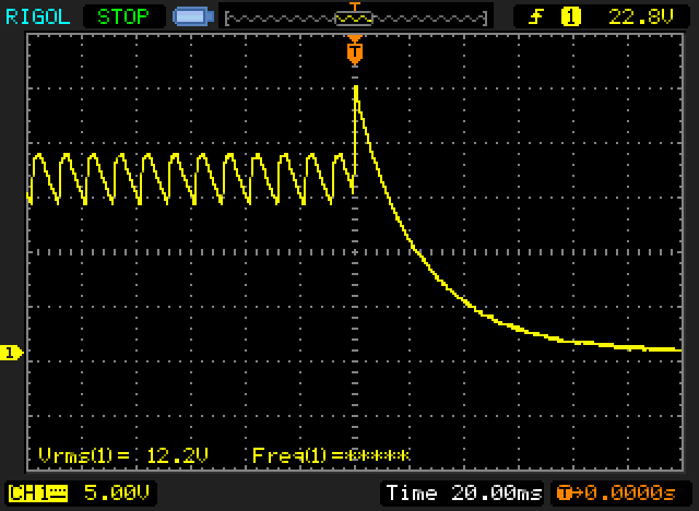
Figure 12.4 - Transformer Voltage 'Surge'
When a transformer is fed from an unstable (negative) impedance such as an arc, it can (and probably will) react at its own self-resonant frequency, and can quite easily generate a voltage that's far greater than the nominal mains, and at a much higher frequency determined by the transformer itself. It's difficult (but not impossible) to draw a useful arc with a small transformer, but it may be quite easy with a larger one - of course, much depends on the transformer itself. Remember that a transformer couples anything that happens on its primary to the secondary, and vice versa. The limit to this is set by the leakage inductance, but the effect is seen easily in the above trace, and there can be no doubt that using an undersized capacitor can cause 'unexpected consequences'. Due to transformer action, any voltage (surge or otherwise) you see at the secondary must also be present on the primary, as determined by the transformation ratio. This was also measured and verified, but isn't shown here.
Note that this effect is not reliable - it took several attempts to capture the peak shown, so it's easy to (mistakenly) assume that the circuit will be fine. All it needs is the right (or wrong) combination of switch-off time with respect to the transformer's current, and a switch that allows an arc as it opens. The transformer must also be subjected to a very light or no-load at the time. Most circuits don't present this condition, so problems are very rare.
Using an additional 33µF cap in parallel with 10µF reduced the maximum peak I saw to about 23V, but with no cap at all, the voltage reached 60V for 32µs across the 2k2 resistor. That's an instantaneous power of 1.6 watts in the resistor. I only managed that once, but had I kept trying it's inevitable that it would have happened again. The worst-case voltage spike you get depends on the transformer itself. Some will produce a large impulse, while others may generate nothing more than some noise.
By its very nature, an arc is an unstable condition and is impossible to predict. However, it's quite obvious that a voltage spike can and does happen. This isn't something that will normally cause a problem with sensible circuits, but it certainly needs to be considered if you are doing something unusual. You will need to provide some additional circuitry to ensure that the peak is absorbed without an excessive 'voltage surge', especially if the output supplies anything sensitive (IC, MOSFET gate, etc.). A TVS diode (transient voltage suppressor) or a pair of back-to-back zener diodes can be used to clamp the worst case voltage to perhaps 24V or so if necessary for your circuit.
The inductance of a mains transformer is not normally part of its specifications. This changes if it's designed for a switchmode power supply or for audio coupling. For normal mains frequency applications, the figure we are interested in is the magnetising current. As shown above in Figure 12.1.1, the magnetising current is non-linear, so if you do need to know the inductance you must take the measurement at a voltage that's well below the nominal primary voltage. If you have a way to monitor the current waveform, you can verify that there is no evidence of saturation at the test voltage (see Project 139 or Project 139A for suitable current monitors).
Once you know the voltage and current you can calculate the impedance, and from that you can work out the inductance ...
XL = V / I (where V is applied RMS voltage and I is RMS current) L = XL / ( 2π × f ) (where f is the applied frequency)
For example, the transformer I used to produce the oscilloscope captures in Figure 12.1.1 draws 7.31mA with a mains voltage of 120V at 50Hz.
XL = 120 / 7.31 = 16.41 kΩ
L = 16.41 k / ( 6.283 × 50 ) = 52.25 Henrys
This is an interesting 'figure of merit', but it's not actually useful for anything. Of course, if you have a need for a 52H inductor you can use the primary winding to get it, but remember that it will start to saturate at not much more than 10mA. If you tried to use it for audio, the distortion will be quite high at even lower currents, especially as the frequency is reduced below 50Hz. In addition, the inductance will almost certainly be non-linear. The test transformer's inductance fell to 42H with a voltage of 35.2V and a current of 2.64mA.
While generally not at all useful, it's important to understand that the inductance ratio of a transformer is based on the square of the turns ratio. A transformer with a primary of 50H and a 10:1 turns ratio has a secondary inductance of 500mH. This might be handy to know if you like to play with mains transformers in reverse (to obtain a step-up), but in general it's not helpful, and nor is it useful for much. It is something that you might need to know sometime though, and it reflects the impedance ratio - also based on the square of the turns ratio.
As noted above, inductance is part of the specification for switchmode power supply and audio transformers. That's because they are operated in a somewhat different way from mains or other transformers. One area of commonality is that saturation must be avoided, and like mains transformers saturation is worse with no load. For the same power output, a switchmode transformer will be a great deal smaller than a conventional transformer operating at 50 or 60Hz. Typical operating frequencies range from a few kHz up to 100kHz or more. As a rough guide, the necessary size of a transformer will halve for each doubling of frequency (and vice versa of course), but there are many other influences that must also be considered. A complete discussion of this is way outside the intent of this article.
Leakage inductance is caused by magnetic flux that fails to include both primary and secondary windings. The things that influence it include the core material, core geometry, winding topology and air gaps (whether intended or otherwise). It's shown as a separate small inductance in series with the winding resistance (see Figure 11.5) and is a parasitic element. For most transformers it's an undesirable characteristic, but in a few switchmode topologies it's actually used as part of the circuit. Details of this are (not surprisingly) not part of this article.
Toroidal cores generally show the least leakage inductance of mains (i.e. 50/60Hz) transformers because the windings encircle the core, and the core itself has no air gaps. A low value of leakage inductance is not essential for mains frequency transformers, but keeping leakage low helps to prevent stray magnetic fields from generating a voltage and current in the chassis and/or nearby wiring. I measured both primary and secondary leakage inductance with a number of transformers I had to hand, and got the following results.
| # | Secondary | VA | Primary | Secondary | Construction |
| 1 | 12.6 | 2 | 762 mH | 2.35 mH | E-I |
| 2 | 15-0-15 | 80 | 6.4 mH | 130 µH | Toroidal |
| 3 | 25-0-25 | 160 | 1.8 mH | 180 µH | Toroidal |
| 4 | 28-0-28 | 200 | 8 mH | 570 µH | E-I |
| 5 | 30-0-30 | 300 | 1.63 mH | 115 µH | Toroidal |
In theory (a wonderful thing ) the leakage inductance of the secondary can be calculated if you know the value for the primary. It's directly proportional to the square of the turns ratio, so for #2 above, the turns ratio is 230/30 (two 15V windings), or 7.7:1 based on the rated voltage (as opposed to the actual turns ratio). With a primary leakage inductance of 6.4mH, the calculated secondary leakage is 108µH. In reality, the turns ratio will be closer to 7:1 to allow for the transformer's regulation (an unloaded voltage of about 33V, which is close to what we'd expect).
The formula now gives the exact figure calculated. The question now is "Just how does one measure leakage inductance anyway?" It's not difficult if you have an inductance meter, because you simply measure the primary inductance with the secondary short-circuited. The 'ideal' part of the transformer is now out of the equation, and what you measure is the leakage inductance. Small transformers can be problematic, because the winding resistance may be so high that it confuses the meter, giving an unrealistically high reading.
The other method is to use a sinewave audio oscillator and an oscilloscope or AC millivoltmeter. Measure the primary resistance (you need this as a reference), and use a resistor from the oscillator that's at least ten times the measured primary resistance. Short-circuit the secondary winding(s), then set the oscillator to a (very) low frequency (~10Hz is suggested) and measure the voltage across the transformer. Next, increase the frequency until the voltage across the transformer has risen by 3dB (1.414 times the initial voltage). Note the frequency.
L leakage = RP / ( 2π × f ) (Where RP is primary resistance and f is frequency)
The useful part of this method is that the winding resistance is immaterial - you will get the right answer regardless of resistance because the resistance is included in the formula. The audio voltmeter you use is important - most digital meters have a very limited high frequency response, and cannot be relied upon to give an accurate reading above 1kHz or so. Unless you are 100% certain that your meter extends to the frequency you need, the reading can't be trusted.
To show how this works, I measured transformer #1 with an inductance meter, which showed a primary leakage inductance of 1.3H. It's really only 762mH when measured using the method described. The secondary leakage inductance was similarly inflated, showing 6.12mH instead of 2.35mH. The primary resistance is 1,077Ω, and the +3dB frequency was 225Hz (now you can calculate it using the formula shown to see the proper result). Remember to remove the short from the secondary before you connect the transformer to the mains!
It's apparent from this that small transformers are worse than larger ones, and E-I laminations are worse than toroidal cores. This is to be expected once you know what you are looking for. However, it's important to understand that this doesn't affect the operation of mains frequency transformers, and while it's common to see 'perturbations' resulting from the interaction of leakage inductance and diode turn-off commutation, this doesn't affect the efficiency or the DC output (see Power Supply Snubbers for a detailed analysis). In some cases, the turn-off impulse might cause some RF interference (conducted or radiated emissions).
However - and this is important - leakage inductance is a critical figure for transformers used in switchmode power supplies. Because these supplies use a high frequency rectangular waveform, leakage inductance causes ringing which can create over-voltages capable of damaging the switching MOSFET(s) or even the transformer's insulation. A snubber network (a series resistor and capacitor - essentially a Zobel network) is almost universally employed to damp the ringing waveform. Minimising leakage inductance means that the snubber isn't as critical and dissipates less power. This becomes more important when high efficiency is expected, because the resistive component dissipates power and generates heat. This can become significant if the transformer isn't designed for low leakage inductance.
There is a huge array of different core shapes, and each has its own advantages and disadvantages. The two most common for commercial and DIY audio equipment are the standard E-I core and the toroidal core, but there are many others. Occasionally you will see C-cores, double-C-cores and R-cores, but these are not as common as the two most popular types.
Ferrites in particular are moulded and fired to get the shape and magnetic properties desired. Because the initial shape is moulded, it's comparatively easy to produce many specialised shapes to suit various applications, as well as the more traditional shapes shown below.
Note that high-permeability cores (toroids, ferrites, C-Cores and R-Cores) are very unforgiving of DC, and adding an air gap (see next section) is not possible with some. Any DC component in either the primary or secondary will cause partial (unidirectional) saturation, which can cause the core to 'growl'. It also causes much higher than normal 'magnetising' current. It's important to ensure that there is no DC component. For example, a 500VA toroidal transformer can be pushed beyond its VA rating just by using a half-wave rectifier! This will occur at a fraction of the rated output current.
Toroidal
Toroidal cores are made from a continuous strip grain oriented silicon steel, and are bonded to prevent vibration and maximise the 'packing density'. It is important that there are no gaps between the individual layers, which will lower the performance of the core. The sharp corners are rounded off, and they are usually coated with a suitable insulating material to prevent the primary (which is always wound on first) from contacting the core itself.
These are very common, and example photos are shown in Part 1. Because the windings are arranged to cover the core as evenly as possible, they have very tight magnetic coupling, low leakage inductance and low flux 'leakage'. Be aware that the Wikipedia page on 'Toroidal Inductors and Transformers' rabbits on ad-nauseam about 'B-Field Containment', which is not applicable (and mainly just bollocks) when applied to mains transformers. The vast majority of the page contains nothing useful.
I do not intend to show the winding methodology for toroidal transformers, as the specialised machinery needed means it is impractical to try winding one yourself. The insulation between primary and secondary is such that it is very difficult to make a Class-II (double insulated) toroidal transformer. One thing you can often do is add a few extra turns (by hand) to obtain a low-voltage secondary, but it's usually impractical to try to add more than 15V or so (30 turns if the transformer uses 2 turns/ volt). Larger transformers need fewer turns, so success is more likely with a 500VA transformer than a 50VA type.
C-Cores
I don't propose to even attempt to cover all core types, but one iron core that warrants special mention is the 'C' core. These were once very popular, but have lost favour since suitable winding machines became available for toroids. They are still a very good core design, and are especially suited where a (fully certified) inherently safe transformer is required (i.e. where the primary and secondary windings are physically separated), and this technique also ensures that the inter-winding capacitance is minimal. It's very uncommon to see the primary and secondary completely separated though. C-cores are made by rolling a continuous strip into the desired shape, and after bonding, it is cut in half. To ensure the best possible magnetic coupling (i.e. no air gap), the cut ends are machined and polished as a pair - it is very important to ensure that the two are properly mated or unacceptable losses will occur. The core halves are commonly held together with steel banding, similar to that used for large transport boxes.

Figure 13.1 - C-Core Transformer
The main disadvantage of the single C-Core arrangement shown above is that its leakage inductance is usually higher than a single winding. Each 'leg' of the C-core (usually) has half of the primary turns and half of the secondary turns. The two can be separated completely, but that reduces efficiency and increases leakage inductance. Although both windings could be placed onto a single bobbin with a pair of cores, it is more common to use four 'C' sections as shown below. This provides more iron (twice as much) and allows fewer turns for a given voltage. Naturally, the double C-Core as shown below cannot be 100% safe, because both windings are wound together in the same way as for an equivalent E-I transformer. While not intrinsically safe, as with any bobbin-wound winding it's still fairly easy to build one that complies with all double insulation (Class-II) standards.
C-cores are not quite as efficient as toroidal cores, but are easier to wind with conventional coil winding machines. The overall efficiency lies between the E-I core and the toroidal. Note that toroidal transformers are very difficult to build so they comply with double insulation standards. I've never seen a double insulated toroidal transformer, except for those that are used in electronic transformers intended for halogen downlights. These have a plastic case that fully encloses the primary, which only has a small number of turns.

Figure 13.1A - Double C-Core Transformer
A sample of ferrite cores is shown in Figure 13.2 - this is but a small indication of the selections available, and most styles are also available in many different grades to suit specific applications.

Figure 13.2 - Some Ferrite Core Styles
One of the shapes shown is also used with laminated steel cores, namely the toroid. Toroidal transformers are very common today, but they require highly specialised machinery to wind the primary and secondary. They are usually the 'preferred' core style for audio amplifiers, because they have very low radiated magnetic fields. Because the core is (almost) perfectly surrounded by the windings, there is very little flux leakage. As always, nothing is 'perfect', but for mains (and output) transformers, toroids provide the lowest flux leakage of any common transformer.
This means that provided the constructor uses sensible wiring (no wires within ~20mm from the transformer), leakage flux will not cause unwanted interference in the audio signal. If the distance from the transformer is over 50mm or so, even 'line-level' audio should not be affected. As with any construction project, it's important to test your layout before it's 'set in stone' to make sure that there is no hum, buzz or other unwanted signal injected into the audio.
E-I Cores
The diagram in Figure 13.3 shows the correct way to stack an E-I transformer. Sometimes manufacturers will use 2 or 3 laminations in the same direction, then the same in the other. This cuts costs, but the transformer performance will never be as good. Alternate laminations minimise the air gap created between the E and I sections due to imperfect mating of the two. It is essential that the laminations are packed as tightly as possible so that the effects of the air gaps are minimal.
For maximum transformer efficiency, the stack should be square if possible. A square stack is one where the height of the lamination stack is the same as the width of the centre leg (the tongue), so the centre looks like a square from end-on. This gives the best possible wire resistance for the core size. Thicker and thinner stacks are commonly used, but this is for expedience (or to minimise inventory) rather than to improve performance.
Figure 13.3 - E-I Lamination Stacking
When a transformer using E-I laminations is bolted together, it is important that the bolts are insulated from the core. If not, this would allow large eddy currents to circulate through the end laminations and the bolts, reducing performance dramatically. For safety, the core should always be bonded to mains earth unless the transformer is rated as 'double insulated'.
"Yes, but what good is that? The laminations are insulated from each other anyway." The inter-lamination insulation is sufficient to prevent eddy currents, but cannot withstand the mains voltage, so in case of electrical breakdown, the core may become 'live' if not earthed.
In order to reduce the radiated flux from an E-I transformer core, you will sometimes see a copper or brass band ¹ wrapped around the winding and the outside of the core, as shown in Figure 13.4. This acts as a shorted turn to the leakage flux only, and greatly reduces magnetic interference to adjacent equipment. The band must be soldered where it overlaps to ensure a very low resistance. Such measures are usually not needed with toroidal transformers, as leakage flux is very much lower, and the core is completely enclosed by the windings.
However, in critical applications a flux band can still be used. For a toroidal, the band is simply wrapped around the outside of the winding and soldered to give a low resistance connection. The band must not be allowed to touch other metal parts that are connected to the mounting bolt in such a way as to form a shorted turn. This will cause a huge circulating current - the fuse will blow if properly sized, or the transformer will burn out if not. It is alright to earth the flux band though, and this will reduce radiation of any HF noise (rectifier noise for example).
( ¹ While I am sure that many people would love to see their local brass band wrapped around a transformer, this is not what I had in mind. It does create an interesting mental picture though
Figure 13.4 - Flux Banded Transformer
Just in case you were wondering, the dimensions of E-I laminations are worked out so that the laminations can be created with no material waste (other than the holes). The relative dimensions are shown below, and are just a ratio of the real dimensions, which will naturally be in millimetres or inches. This arrangement is known as a 'scrapless' lamination because there is an absolute minimum of waste material.
Figure 13.5 - Assembled Laminations and Punching Dimensions
The magnetic path length is the average for the dual path shown in the assembled lamination drawing, and is generally assumed to be 12 (units). This may be thought a little pessimistic, but is the commonly accepted figure. The winding window size is restricted by the punching dimensions, and it is critical that the maximum usage is made of the limited area available. Should the winding wire be too thin, there will be plenty of room, but copper losses will be excessive. Make the winding wire too thick, and the completed winding will not fit into the available space. Additional space must be allowed for the winding bobbin, and for inter-winding insulation and the final insulation layer.
R-Core
These are relatively uncommon, which is a shame. The essential parts of an R-Core are shown below, and the core is a single strip of GOSS (grain-oriented silicon steel), specially cut so that when rolled into the core shape it provides a circular cross-section. The bobbins spin freely on the core, and are provided with a 'drive' system on one or both bobbin cheeks. The bobbins are made in two parts, and are added to the core after manufacture. Winding requires a special machine, but it's something that a determined hobbyist can build.
Figure 13.6 - R-Core Transformer Core And Bobbins
In most cases, the bobbins are wound with half of the primary and half of the secondary on each. Unlike a toroidal transformer, it's easy to include insulation that takes the assembly to Class-II (double insulated) standards. In a few cases, the primary and secondary are on separate bobbins where very high insulation levels are needed. This increases leakage inductance and reduces (magnetic) coupling, so it's not ideal for high performance. However, like a C-Core, this form of winding may be used where very high isolation between primary and secondary are essential.
Many R-Core transformers are fitted with a 'flux band' (as described above) as a matter of course. This is necessary to prevent leakage flux from 'contaminating' signal wiring, because there is a slightly greater flux leakage from an R-Core than an equivalent toroidal transformer.
DC flows in the windings for any transformer that is used for 'flyback' switching supplies or SET power amplifiers, to name but two. The effect is that the DC creates a magnetomotive force that is unidirectional, and this reduces the maximum AC signal that can be carried before saturation in one direction. Indeed, the DC component may cause saturation by itself, so the transformer would be rendered useless as a means of passing the AC signal without severe degradation. Even the use of a half wave rectifier will introduce an effective DC component into the windings, and these should be avoided at any significant power level (i.e. more than a few milliamps).
To combat this, transformers that are subject to DC in the windings use an air gap in the core, so it is no longer a complete magnetic circuit, but is broken by the gap. This lowers the inductance, and means that a larger core must be used because of the reduced permeability of the core material due to the gap. An air gap also increases leakage inductance because of the flux 'fringing' around the gap, and resistive (copper) losses are increased as well, because more turns will be needed.
It is beyond the scope of this article to cover this in great detail, but it does impose some severe restrictions on the design of transformers where DC is present. This is (IMO) one of the biggest disadvantages of the SET amplifier so popular with audiophiles, as it almost invariably leads to unacceptable compromises and equally unacceptable distortion (both harmonic and frequency).
In some designs, it is possible to eliminate the DC component by using a tertiary winding that carries ... DC. If the additional winding can be made to induce a flux that is equal and opposite that of the bias current, then the quiescent flux in the transformer can be reduced to zero (where it belongs). The disadvantage with this is that it requires an extra winding, and that takes up valuable winding space on the core. It is also a difficult technique to get right, and is not often seen these days. It was a popular technique in telecommunications equipment at one time, and meant that smaller transformers could be used for the same performance.
E-I transformers all have a minuscule 'air gap' because of the way the laminations are assembled. With care, this can be almost be considered negligible, but it cannot be eliminated. C-cores will have their cut ends machined to minimise the effect, but again, it cannot be eliminated entirely. The toroidal core has no air gap at all, and is therefore more efficient (magnetically speaking) - they are utterly intolerant of DC in the windings. With large toroidal transformers the primary resistance is very low, and even tiny DC voltages on the mains will cause partial saturation.
This is commonly heard as a growling noise from the transformer, and if bad enough you'll hear it just before the fuse or circuit breaker opens. It's easy to get several times the normal full load current to flow in the primary with asymmetrical mains waveforms that have an effective DC component. See Blocking Mains DC Offset for more information on the problem and how to fix it.
There is an enormous range of core materials, even within the same basic class, so I will mention only a few of the most common. All materials have some basic requirements if they are to be used with AC (for transformers, rather than solenoids or relays, which can operate with DC). The core cannot be solid and electrically conductive, or excessive eddy current will flow, heating the core and causing very high losses. Therefore, all cores use either thin metal laminations, each electrically insulated from the next, or powdered magnetic material in an insulating filler. The list below is far from exhaustive - there are a great many variations of alloys, and I have mentioned only a few of those that are in common use.
GOSS
Commonly thought to be an acronym for 'Grain Oriented Silicon Steel', it's actually the name of the man who invented it - Norman P. Goss (US Patent 1965559). See Wikipedia for a bit more.
Silicon Steel (General Information)
Typically, soft (i.e. low remanence) magnetic steel will contain about 4% to 4.5% silicon, which lowers the remanence of the steel and reduces hysteresis losses. Normal mild steel, carbon steel or pure iron has quite a high remanence, and this is easily demonstrated by stroking a nail (or screwdriver) with a magnet. The nail will become magnetised, and will retain enough magnetism to enable it to pick up other nails. The addition of silicon reduces this effect, and it is very difficult to magnetise a transformer lamination strongly enough so it can pick things up.
This is not to say that the remanence is zero - far from it. When a transformer is turned off, there will often be residual magnetism in the core, and when next powered on, it is common for the transformer to make noise - both toroids and E-I transformers can sometimes make a noise (sometimes rather loud) when power is applied. This is due to core saturation and inrush current - see Section 12.1 above for a more complete description.
Silicon steel and other metal (as opposed to ferrite) materials are normally annealed by heating and then cooling slowly after stamping and forming. This removes most of the internal mechanical stresses caused by the stamping or rolling operation(s) - these stresses reduce the magnetic properties of the material, sometimes very dramatically.
CRGO - Cold Rolled Grain Oriented Silicon Steel
Like many steels, this version is cold-rolled to obtain the required thickness and flatness needed for a transformer core. The magnetic 'grain' of the steel is aligned in one direction, allowing a higher permeability than would otherwise be possible. This material is ideal for toroids and C-cores, since the grain can be aligned in the direction of magnetic flux (i.e. in a circular pattern around the core). It is less suited to E-I laminations, because the flux must travel across the 'grain' at the ends of the lamination, reducing permeability.
CRNGO - Cold Rolled Non Grain Oriented Silicon Steel
Generally more suited to E-I laminations, this is essentially the same process as the CRGO, but the magnetic grain is left random, with no alignment of the magnetic domains. Although this reduces overall permeability, the effective permeability may be better with stamped laminations (as opposed to rolled, as with toroids and C-cores).
Powdered Iron
A soft ferrite ceramic material, used where there is significant DC in the winding. Powdered iron cores have relatively low permeability (about 90, maximum), and are designed for high frequency operation. These cores are most commonly used with no air-gap, and will not saturate easily. Typically used as filter chokes in switching power supplies, and as EMI (Electro-Magnetic Interference) filters - the toroid is the most common shape.
Ferrite
Soft ferrites are the mainstay of switching power supplies, and low level high speed transformers (such as might be used for network interface cards and small switching transformers. Ferrites are available with outstanding permeability, which allows small cores with very high power capability. Flyback (a type of switchmode operation) transformers in particular are usually gapped because of the DC component in the primary current.
High permeability ferrites are also very common in telecommunications and for other small audio frequency transformers where very high inductance and small size is required.
MuMetal
Named after the symbol for permeability (µ), as one might expect, this material has an extraordinarily high permeability - typically in the order of 30,000. It is commonly used as magnetic shielding for cathode ray tubes in high quality oscilloscopes, screening cans for microphone transformers, and as laminations for low level transformers. The maximum flux density is quite low compared to other metallic materials. Apart from being relatively soft, if dropped, the magnetic properties may be adversely affected (MuMetal requires careful annealing to ensure that its magnetic properties are optimised).

Note that the reference to 'soft' materials does not mean their physical hardness (most are physically hard to very hard), but describes their magnetic properties. A 'hard' magnetic material is required for permanent magnets, as it has high retentivity. 'Soft' materials are designed to have very low retentivity, so they don't become magnets themselves.
An ideal transformer has zero distortion, but there are zero ideal transformers. Therefore, it can be deduced that transformers do have distortion, but how much?
The answer depends entirely on how the transformer is used. When supplied from a voltage source of zero ohms impedance, the real life transformer has very little distortion. The winding resistance of the transformer itself is effectively in series with the 'ideal' winding, so to get a true 'zero resistance' source you need a negative impedance driver. If the negative impedance is made to be the same magnitude as the winding resistance (a positive resistance/ impedance), the two cancel. This is not trivial, but it can be done, and there is some information about the technique in the Audio Transformers article.
Any transformer operating at low flux density, and with a low impedance source, will contribute very little distortion to the signal. As frequency decreases, and/ or operating level increases, the limits of saturation will eventually be reached in any transformer, and distortion will become a problem. This is not really an issue with mains power transformers, but is very important for valve output and line level coupling/ isolation transformers, particularly at low frequencies.
The distortion characteristics of transformers used as valve output devices is a complex subject, and will not be covered here. Suffice to say that the normal methods of determining the turns per volt, based on the bare minimum lowest frequency response will give unacceptably high distortion levels at low frequencies.
It's important to note that connecting a transformer directly to the output of a conventional (transistor) audio power amplifier can have unexpected and serious consequences. If the core saturates due to a DC 'event', the amplifier will either go into VI limiting mode (due to protection circuitry), and/or it may fail completely. The 'event' can be as seemingly innocuous as breathing heavily onto a microphone, which causes a large very low frequency component that causes core saturation. See High Voltage Audio - Saturation for a complete discussion on this topic.
There is also a discussion of valve audio output transformers in the valves section. See the Valves Index for a listing of the articles available. The 'Design Considerations' articles in particular look at transformer behaviour and requirements.
Transformers can often be reused, with the new usage completely different from what was intended. Great care needs to be taken though, as there are a few traps with some transformers used in consumer equipment. In general, a transformer taken from an old amplifier will be fine to use in a new amplifier, but not all transformers found in consumer goods are usable for anything unless you know exactly what you are doing.
A question that was raised on the ESP forum some time ago related to the use of old microwave oven transformers (MOT for brevity). While the secondary voltage is much too high (typically around 1.1 to 1.5kV RMS), it was suggested that the high tension winding could simply be removed and a new secondary wound to give the voltage needed. While this will work, beware of current (cost cutting) manufacturing trends!
It is very common that an MOT taken from an oven that is less than ~20 years old will be wound such that the transformer is well into saturation at no load. In one unit I tested, the unloaded current was 1.2A (yes, 1.2A - not a misprint). The core started to saturate at only 150V, and by 240V was very heavily saturated. In its intended use, this will not cause a problem - remember that core flux decreases when the transformer is loaded, and a microwave oven also has a fan, and normally never runs for very long. The transformer is never operated unloaded unless the magnetron supply circuit is faulty or the magnetron itself is dead.
An amplifier normally applies very light loading most of the time. Operating a transformer such as the one I tested in an amp would result in the transformer overheating (288VA of no-load heat), as well as unacceptable overall efficiency for the amp itself. In addition, a MOT is not designed for low leakage flux, so will dramatically increase hum levels because of induced currents in the wiring and chassis. To add insult to injury, the transformer was also quite noisy (mechanical noise due to magnetic interaction between the core and windings, plus [maybe] some magnetostriction), and that alone would make it unsuitable for use in a hi-if system (assuming that it was electrically suitable).
As you can see from the above, the MOT is completely unsuitable for continuous duty at light loading - in fact, it is not even designed for continuous duty. While it is possible to add more turns to the primary, a great many additional turns would be needed to reduce the flux to below saturation. In addition, adding primary turns means that the insulation must be perfect to prevent potentially fatal mishaps.
All transformers that you intend for reuse should be examined on their merits, and tested in a controlled environment to ensure that they will survive in their new role. Just because a transformer was used in one piece of equipment does not mean that it can be used in any other equipment, as the design criteria are often very different indeed.
If you are satisfied that a transformer is suitable for the new task you are about to set it towards, then turns can be removed from or added to the secondary to get the voltage you need. Do not tamper with the primary unless you understand the insulation requirements, and can ensure that the final transformer is at least as safe as it was when you found it. This article will not even try to cover the task of rewiring the secondary - if you don't know how, and can't work it out, then you shouldn't be messing with transformers in the first place.
| VA | Resistance | Regulation | VA | Resistance | Regulation |
| 4 | 1100 | 30% | 225VA | 8 | 8% |
| 6 | 700 | 25% | 300 | 4.7 | 6% |
| 10 | 400 | 20% | 500 | 2.3 | 4% |
| 15 | 250 | 18% | 625 | 1.6 | 4% |
| 20 | 180 | 15% | 800 | 1.4 | 4% |
| 30 | 140 | 15% | 1000 | 1.1 | 4% |
| 50 | 60 | 13% | 1500 | 0.8 | 4% |
| 80 | 34 | 12% | 2000 | 0.6 | 4% |
| 120 | 22 | 10% | 3000 | 0.4 | 4% |
| 160 | 12 | 8% |
Expanding on the table shown earlier, this covers a wider range but has only the info you really need to judge the approximate VA rating for a transformer, assuming you have one with no indication of its ratings. The above table is only a rough guide - it is not intended to be treated as gospel, because there are many conflicting requirements that can influence the winding resistance in either direction. As noted, the figures are for nominal 230V transformers - if you are in a 120V country, the resistance values shown should be divided by 4 (close enough).
Regulation is often misunderstood, and the values shown are (again) approximate. Transformer manufacturers almost always quote regulation based on a resistive load, which is the best case. In real applications, regulation will be (often considerably) worse than the value quoted or shown above. See 11.3 for a detailed explanation.
My thanks to Phil Allison for the data in the above table.
At some point, most people involved in electronics will come across a transformer (or other wound component) with one or more shorted turns. This is almost always fatal (for the wound component, not the user ). Regardless of the size of a transformer, just one shorted turn means it's no longer a transformer, just a paperweight (or boat anchor). For larger transformers, a shorted turn will cause the fuse to blow with just the transformer connected (no load). Smaller transformers will have a higher than normal dissipation, but for those under ~15VA (this varies) they'll often be fitted with a thermal fuse. This is usually buried in the windings and is rarely accessible without removing the entire secondary winding.
There are tests you can run to check for a shorted turn, but very high voltages can be generated, even by modest transformers. To start, connect a high-voltage capacitor between (220nF up to 470nF) across the primary. The basic test is to apply DC to the primary (at no more than about 10mA) and switch it off quickly. A good transformer will produce a waveform similar to that shown below (red trace). You are specifically looking for ringing (a damped oscillation). The capacitor interacts with the transformer's inductance to produce the damped ringing. Shorted turns damp the resonance dramatically. Current flow was interrupted at 70ms on the graph.
Figure 16.1 - Good transformer (Red), Shorted Turn (Green)
The above was taken from a simulation (the time scale was arbitrarily started from zero), and the reality may be a little different. I ran a test on a couple of transformers and obtained results that were almost identical. The results you see will be different, and it varies with the size (VA rating) of the transformer and how 'good' the short circuit is. I simply added a shorted turn through the centre of the two toroidal transformers I tested (one was 20VA, the other 300VA).
It's important that the 'exciting' current is kept low, or the voltage spike will be extreme with a good transformer. Also, understand that this test is not 'definitive', as so much depends on the nature of the shorted turn. If more than one turn is shorted (which isn't uncommon), the negative-going peak will be a much lower voltage, and as shown above the worst-case is either a shorted secondary or many shorted turns. The 'ringing' disappears completely, with only a subdued negative transition ('Many Turns' curve). Ideally, you'd test the suspect transformer along with another of roughly the same VA rating and core style.
In some cases, the short may be temperature dependent, or may even disappear when a toroidal transformer's mounting bolt is loosened. The transformer is still 'cactus', and it must not be re-used. Doing so is dangerous, as there's always a (admittedly small) risk that it may develop a primary to secondary short, or it may cause such severe overheating that fire is a possibility. It's worthwhile to run a few tests for yourself to see the results, and if possible, create a shorted turn with a piece of fairly thick copper wire so you can see the effect yourself. Remember to remove the shorted turn before using the transformer!
Of all transformers, one of the least understood (or most misunderstood) is the current transformer (CT). While these seem initially to defy the general rules of transformers, they actually do no such thing. Should you search the Net, you can find a great deal of information, but much of it is extremely technical (excessively so for a general understanding) or in some cases, very misleading. Some of it is just plain wrong. The information below is verified by testing and/or simulation. Note that I have not attempted to look at phase angles or vector/ phasor diagrams. These may be interesting, but are irrelevant to this explanation because they only become significant when more complex measurements are needed and/or absolute phase becomes important.
Where an ideal voltage transformer has a very low output impedance and behaves as a voltage source, an ideal current transformer has a very high output impedance, so acts as a current source. Within reason, the secondary current is unaffected by the load resistance (a low to very low resistance is preferred). The load connected across the secondary is known as the burden. This may be a resistor, an ammeter, or other equipment that is designed to apply the correct load to the CT's secondary circuit. The term 'burden' is used to differentiate it from the 'load' which is assumed to be the load (e.g. motor) on the (usually) single-turn primary of the current transformer.
Current transformers are used to measure the current in a conductor, and most commonly use only a single cable or bus bar passing through the centre of a toroid. The secondary winding is conventional (wound around the core in the usual manner), and is specified by the turns ratio, rather than as a specific voltage as seen with conventional voltage transformer specifications. Indeed, voltage is not the preferred output from a CT - because it's a current transformer, we expect to monitor output current. The burden resistor (where used) acts as a current to voltage converter, and the lower the value the better.
Traditional current transformers (as used in switchboards and power stations/substations for example) use laminated transformer steel cores, have limited bandwidth, and are generally designed to provide an output of 5A to drive a moving-iron meter movement. These may be thought to be 'true' current transformers, in that there is rarely any requirement to measure a voltage across a defined resistance. However, any load (meter or other indicating device) will always have some resistance, so there will always be a voltage developed across the burden - intentional or otherwise.
The ratio for these 5A secondary transformers is usually given as 1000:5 for example - 1,000A input drives a 5A meter to full scale. They are still surprisingly common, because most modern indicators and protective devices (including fully electronic types) are still designed for a 5A input (this is an industry standard for mains power monitoring). The typical burden for a 5A output is 0.2 ohm, so 1V will be developed across the burden at full current. Note that wiring resistance between the CT and the instrument increases the effective value of the burden, and this may cause inaccuracies if the cable is not sized appropriately.
For workshop use, we use electronics for most measurements (digital readouts for example), and these require a voltage input. This is obtained by monitoring the voltage across a defined resistance value, and operating secondary current is generally very low - certainly no more than 1A, but more typically less than 100mA. A current transformer with a ratio of 1000:1 will give an output current of 1mA/A of input current. If high currents need to be measured, the ratio may be higher or the burden lower - if 1,000A needs to be measured with output current appropriate for modern electronics, the burden could be reduced to 1 ohm, so 1,000A will give an output of 1A - 1V across 1 ohm. However, it is important that the transformer is actually rated for 1,000A - you can't expect a 10A CT to remain linear if both the primary and secondary current is 100 times greater than it's supposed to be. Not only will the core saturate, but the secondary winding may burn out because of excessive dissipation.
Naturally, one can still use an industry standard 5A current transformer, even to feed a modern true RMS meter. As noted above, the typical burden is 0.2 ohm, 1V will be developed across it at full current, and the burden (if purely resistive) will dissipate 5W. These figures are all within the boundaries of normal low-power electronic equipment. However, few of us need to be able to measure 1,000A in our workshops unless we happen to be building a welder. Most loads are less demanding, and call for a current transformer designed for lower output current.
We know that to measure current we can simply apply Ohm's law - include a series resistor and measure the voltage across it. However that means that there will be a voltage dropped across the resistor, and it will dissipate power. This becomes irksome in an industrial application, where the current we wish to monitor may be thousands of amps! There is also a small matter of safety - a current transformer provides an important safety barrier, in that the secondary is completely isolated from the single turn primary. As with all transformers, current transformers are only usable with AC.
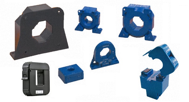
Figure 17.1 - A Selection Of Typical Current Transformers
The CTs shown in Figure 17.1 are but a tiny sample - there are hundreds of different styles available, with current ratings from a few amps to thousands of amps, output currents of a few milliamps up to 5A, and designed for 50/60Hz up to hundreds of kHz (sometimes used in large switchmode power supplies). It is far more important to understand the general concepts - appearance and the finer points of the design are unimportant as long as it works as intended. Current transformers are based on ampere-turns as are all transformers, but it's not considered an especially important factor for a conventional voltage tranny. With a CT, ampere-turns is the defining factor, and the main consideration for both primary and secondary is current, not voltage. It follows that the secondary should be loaded so that it provides an output current rather than a voltage.
A typical low current (less than 200A) instrumentation current transformer may have a turns ratio of 1000:1 - this means there are 1000 turns on the secondary, and it's assumed that the primary will be a single turn. The turns ratio is determined by the primary current and the required secondary current, and varies widely with real CTs. The ratio can be anything between 100:5 (5A output at 100A load current), up to around 2500:1 for specialised applications. Full scale secondary current ranges from a perhaps 100mA up to 1A or 5A (the latter is still very common). Note that the ratio for 5A output CTs is almost always stated as nnn:5 (e.g. 250:5) to differentiate it from low output current devices.
Primary inductance is minimal, usually only a few microhenries at most, and that's for 50/60Hz operation. 1A primary current results in 1mA secondary current (1000:1). You may well ask how on earth a transformer with such a low primary inductance can possibly even function with such a low inductance, but in doing so you'd miss the point.
Primary inductance is necessary for a transformer that is connected across the mains, because the inductive reactance limits the magnetising (no-load) primary current. With a current transformer, there's no requirement to limit the current, as that is done by the load itself. The current drawn is only monitored by the current transformer. Its very purpose is to introduce the minimum possible additional impedance into the circuit. The extremely low primary inductance is the reason the CT acts as a current source - output (secondary) current is directly proportional to primary current, provided core saturation is avoided - an absolute necessity.
I measured the primary inductance of the 5A, 1000:1 CT that I used for other tests. My inductance meter insisted on using 1kHz for the test, but that's alright as the readings can only be considered as representative at best. Tests were done with 1 and 10 turn primaries, and with the secondary O/C (open circuit) and with a 100 ohm burden. The measured values are ...
Primary Turns Primary Inductance Sec Open Sec 100Ω 1 1.5 µH 0.2 µH 10 144 µH 1.2 µH
The very low inductances measured are unlikely to be especially accurate, simply because they are at the limits of my meter's measurement capability. The figures are still interesting though. The primary inductance value with an open circuit secondary is not useful, but is included so that the effect of the burden is made apparent. As noted below, a current transformer should never be operated with an open circuit secondary winding. The rather dramatic inductance increase when the burden is disconnected is an immediate indication that bad things are likely to happen.
I ran several tests on this current transformer. The recommended burden is 100 ohms, so at full current (5A) you will measure 500mV across the burden resistor. With 10 turns on the primary full scale current is 0.5A ... exactly as expected. At 50Hz and full current, the voltage across the burden resistor was 500mV. I wanted to see the saturation characteristics, and even at double the rated current (10A) there was no visible saturation until the frequency was reduced to 10Hz. This is a good indicator of the large safety margin employed. The CT itself falls into a category that is sometimes referred to as a 'wide band' type. The ferrite core has lower high frequency losses than a laminated steel core, and therefore operates up to much higher frequencies.
Although the primary is considered a single turn, in almost all cases it simply passes through the centre of the current transformer core (see Figure 17.2). There is no requirement to make a complete turn in the traditional sense. When current transformers are mounted on heavy-duty bus-bars rather than flexible cables, it's not even possible to make a complete turn, and fortunately there is no need to do so.
The burden resistance is placed in parallel with the secondary winding. The voltage across the burden may be monitored (rather than the current through it) because it is often easier to have an output voltage to work with than an output current. However, in some cases a small (AC) ammeter may be connected directly across the output terminals so that the primary current may be monitored directly. A simple opamp circuit can also be used to convert current to voltage. Note that it is perfectly alright to short-circuit the secondary winding, because only the designed current will flow (10mA for the example shown below, with a load current of 10A). The CT used for my tests will work perfectly with a 10 ohm burden, or even a short circuit (although the latter is not useful). Naturally, as the burden is reduced, so too is the voltage developed across it.
While the recommended burden resistance is 100Ω, you can measure current greater than the rated value by simply reducing the burden resistance. If you use a 10Ω burden, the output voltage is reduced to one tenth of that obtained with 100&Omeag;. At 5A you'll get 50mV, but the maximum current allowed is increased by a factor of at least five. The 5A CT is now capable of measuring at least 25A, but in reality that may be extended much further. I've used an AC1005 current transformer with over 100A by using a 10Ω burden, with no indication of saturation. Project 207 describes a high current AC source I built to allow tests on circuit breakers or to stress-test other circuitry.
Figure 17.2 - Current Transformer Wiring Diagram
It's very important that the burden is not disconnected during normal operation, as the secondary voltage can rise to a possibly hazardous level. Not usually a problem with small CTs, but if the tranny is monitoring a thousand amps or more it can become a serious risk. It's entirely possible that the unterminated output voltage can exceed several thousand volts. The available current is usually low for small CTs, but with one intended for 5A output it will be extremely dangerous. With CTs used in large industrial applications, it's not uncommon to find that there is a shorting strap that must be connected before the remote ammeter or other equipment is disconnected for service or calibration (for example).
Most CT specifications will state the optimum (or maximum) burden resistance. For the 1000:1 current transformer that I have, there is a table of output voltage vs. burden resistance, with 100 ohms being the preferred value. Other (higher) values can be used, but at the expense of reduced bandwidth and/or linearity. Lower values may also be used.
At the 5A rated input current, the secondary current is 5mA (1000:1 ratio). With a 100 ohm burden, the voltage across the resistor is 500mV at full rated primary current. This is simply based on Ohm's law ...
V = I × R
V = 5mA × 100 ohms = 0.5V
Interestingly, if no secondary current is drawn (no burden resistor or too high in value) core saturation will occur at a relatively low primary current (well below the rated current), and the output voltage will be both much higher than expected and very distorted. Unlike traditional voltage power transformers, current transformer cores must be operated well below the point where even the slightest saturation effects are noticeable, or reading errors become apparent. These transformers are used as a way to measure or monitor the current, so saturation distortion has to be as low as possible to ensure measurement accuracy. Most CTs have a large safety margin to ensure accuracy.
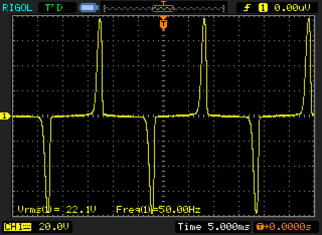
Figure 17.3 - Current Transformer Saturation
This is what happens with 10A primary current but with no burden. Although the test transformer is rated for 5A, it performs perfectly at double the rated current with the 100 ohm burden in place. Without the burden things are very different! As you can see, the output waveform is highly distorted due to heavy core saturation. Re-connecting the 100 ohm burden instantly restored the normal voltage and waveform, in this case a clean sinewave at 1V RMS.
Without the burden, the core is pushed into hard saturation and the secondary voltage rises significantly (and alarmingly). At 50Hz and 10A, the output voltage is very distorted, and reached 80V peak and 22V RMS. With 10A (but at an increased frequency to avoid saturation) I was able to measure 200V RMS at the secondary. This also reverted to the expected 1V RMS as soon as the 100 ohm burden was re-connected. Imagine what might happen to you if the transformer had a 5A secondary and was monitoring 10,000A instead of only 10A, and the burden was disconnected. Yes, the impedance is high, but with 5A output current available it's extremely dangerous - and the very high voltage can also damage the insulation on the secondary winding.
There are some pretty bizarre 'explanations' on the Net as to why the voltage rises when the load (burden) is removed. The simple (and easiest to understand) is that as noted, it is a current transformer. The secondary's output is defined as a current, not a voltage. A current source (and that's what a CT really is) will always try to force the correct current to flow in its load (the burden) regardless of impedance. Naturally, this can only occur within the limitations of the device itself, but it is this very property that causes the voltage to rise. If the burden is removed, an ideal current source would have an infinite voltage, since it is attempting to force current into an open circuit. In reality, normal losses (core loss, core saturation, leakage inductance, finite insulation resistance etc.) will limit the actual voltage, but in some cases not before the insulation fails and the transformer is ruined and/or the electrician's family is a member short.
Compare this with a voltage transformer, which will try to maintain the designed output voltage regardless of how much current is drawn. Again, losses mean that a short circuit (the voltage transformer's equivalent of a current transformer's open circuit) will not cause infinite current to flow. The end result will be the same for both though - a broken transformer. It's easy to protect both - a fuse for the voltage transformer and something to limit the output voltage to a safe value for the current transformer (discussed below).
As has been shown in the measured data, when the burden is removed there is a dramatic increase of the primary inductance, which means that the voltage across the (most commonly) single turn primary will increase proportionally. More voltage across the primary means more voltage across the secondary - this relationship is immediately obvious. A simulation proved this quite convincingly, and matched my measured results very closely. Now you know the real reason the voltage increases - perfectly simple and makes complete sense ... but it's still a current source.
To prevent CT failure, just add a safety voltage clamp such as a MOV (metal-oxide varistor) or a couple of zener diodes (wired in series, back-to-back) in parallel with the secondary winding. This is cheap and effective safety measure for small CTs with low output current. At the low voltage normally expected from the CT, the safety clamp will be inactive and will not influence the reading. For a large CT operating with a 5A output current (for example) a somewhat more robust solution is called for, but the principle is not hard and is a lot cheaper (and kinder) than replacing a failed transformer or electrician.
Something that you rarely see mentioned is both interesting and useful, and is touched upon above. If a current transformer is rated at 5A (like the one I used for my tests), you can get improved accuracy at low currents by winding more turns through the core. If you were to make the primary winding 10 turns instead of the normal single turn, you'll get the full 5mA rated secondary current with only 500mA in the primary. We expect that when turns are added to the primary, the voltage is reduced - in this respect a current transformer appears to defy the normal rules that apply to transformers. I hasten to reassure the reader that no rules are broken, and the laws of physics as we know them are still firmly in place. (Manufacturers know about this and may provide extensive help for the user, but most articles on the Net don't mention it.)
Remember ampere-turns mentioned earlier? There's the clue to what happens - multiply the current in Amps by the number of turns. If 1A flows through 1 turn, that's 1 ampere-turn. If we have 10 turns and 100mA, that's also 1 ampere-turn. On the secondary side (1000:1 tranny) we have 1,000 turns at 1mA - still 1 ampere-turn. The same concept applies regardless of the turns ratio or primary/ secondary current.
One thing must be made perfectly clear - the current used in the measuring circuit attached to the secondary is not free energy . If we have a primary voltage of 230V, a load current of 10A and a secondary current of 10mA into a total resistance of 100 ohms (1V), the voltage to the load is actually 229.999V (1mV difference, ignoring losses). The load power is reduced by 10mW. This is easily determined ...
P = V × I
P = 1mV × 10A = 10mW (primary side - transferred to the secondary)
P = 1V × 10mA = 10mW (secondary - this power is dissipated in the burden and winding resistance)
The loss of 10mW is verging on insignificant, but it is important to understand that there are losses, and like all losses they accumulate. Adding a current transformer to a circuit is unlikely to cause a measurable loss in reality, because normal cable resistance in the power circuits will cause losses that are orders of magnitude greater.
Predictably, you won't find any 1A CTs with a 5A output - the output from a current transformer is always expected to be a very small fraction of the load current.
During my tests, I found that the high frequency limit was much greater than that of the amplifier I used to test the tranny - there was no evidence of HF rolloff, even at 20kHz. When the correct burden resistor is used, most small current transformers' bandwidth will usually far greater than necessary for most normal current measurements.
However, be aware that high current CTs using a laminated steel core will have much narrower bandwidth, which may only extend to a few hundred Hertz. Iron losses increase dramatically with increasing frequency and cause considerable HF loss. Some current transformers use a small bobbin around part of a split laminated steel core (commonly found in clamp meters), and these have very poor HF performance. It's also worth noting that there are now isolated current sensing ICs (using Hall effect sensors) that replace many traditional CT applications on PCBs. However, the CT has been with us for over 100 years, and it's unlikely that anything will replace completely it for a very long time.
The Hall-effect current monitoring devices as complete ICs are useful and interesting, but noise performance in particular is woeful compared to a current transformer. A Hall-effect device that can handle 10A will be all but useless at 50mA due to noise, and at a current only marginally higher than the rated value, the unit will become highly non-linear. By way of comparison, the 5A current transformer I used for these tests can handle 10 times the rated current (50A) with very little non-linearity!
This has been a short introduction to the wonderful world of the current transformer, and hopefully it will clear up some of the misconceptions that seem to abound. There is nothing difficult, just a different way of looking at a familiar component. Most people will never use a current transformer, and many won't even have known that such a device existed until they read this chapter.
For anyone who needs to monitor current during servicing or design work, have a look at Project 139. This uses a Hall effect sensor rather than a current transformer. This type of transducer has a wider range, better high frequency response, and are more flexible than current transformers. They also work with DC which can be an advantage. For those who don't need the enhanced bandwidth or gain, see Project 139a - a simplified version of the current monitor that uses a miniature 1000:1 current transformer (same as the one that was used for the tests described here).
It's worth noting that you can use an opamp as a current-to-voltage converter. However, there is rarely any need to do so because the recommended burden resistor will provide more than acceptable accuracy for anything other than extreme precision measurements. Because of this, an opamp I/V converter won't be described since it is unnecessary in 99% of normal applications, and requires great care to ensure that the circuit is stable, does not create any DC offset, etc.
It's also worthwhile to understand that any toroidal transformer can be used as a current transformer. Simply pass the current-carrying wire through the centre, and voila! A current transformer is created. While this definitely works (yes, I've tried it), determining the optimum burden resistance will be tiresome, and unless you perform a measurement to determine the turns ratio and work out the number of primary turns, calibration will be uncertain. In addition, toroidal transformers (even small ones) are much more expensive than a typical dedicated current transformer, but it's still a trick you can use if you need to measure high current and don't have a suitable current transformer handy.
A variation on the 'traditional' current transformer is the Rogowski coil, named after its inventor (Walter Rogowski). This coil does not use a core, and is deliberately made in such a way as to allow a gap in the winding so it can be placed around a current-carrying conductor without having to break the circuit. As shown below, the 'other' end of the winding runs through the centre of the turns, so the two ends of the winding are available at one end of the coil. The physical construction varies widely, with typical coils rated from 30A up to 6,000A or more. Most use some kind of 'joiner' to ensure that the two ends are aligned the same way with each usage. This reduces measurement errors.
Figure 17.4 - Rogowski coil
It appears common to use a thicker wire or a flexible tube through the centre, and that creates a handy 'former' for the windings. If the centre winding is made from a suitable (non-magnetic) material, it's easily bent around the conductor to be measured. The output of a Rogowski coil is dependent on the rate of change of load current, and an integrator is required to obtain an output that matches the original load current waveform. It's unlikely that many readers will have a use for Rogowski coils, but if you do, there's a great deal of information on the net. Consequently, I do not intend to go into much further detail.
Sensitivity is somewhat lower than traditional current transformers, although it's easily amplified. Unlike a 'normal' current transformer, there is no high voltage generated if the coil is open-circuit, but it's also important to position a Rogowski coil properly (ideally so the current-carrying conductor is centred through the coil). With many, the error is small, but not all behave the same way. Linearity is very good, because there is no magnetic core to saturate at high currents.
This isn't something you will find much information about, and from various circuits I've seen on the Net, it's something that may even be completely ignored. In general, it's accepted that there will be (or should be) no DC at all in the windings of a transformer, but it's easy to make an assumption or 'simplification' that has fairly dire consequences. Just adding a half-wave rectifier is all that's needed, and a surprisingly small current will cause a large increase in the transformer's magnetising current. A few hundred milliamps might be enough to overheat even a fairly large transformer to the point where it fails.
Figure 18.1 - Transformer Test Circuit
The current transformer is actually Project 139A, a simple and cheap current transformer in a box with mains input and output sockets. It's an extremely useful piece of test gear, and was used for all current waveform traces shown in this article.
The test circuit used is shown above. By switching in (or out) the second diode it was possible to measure what happens as the circuit is changed from full wave to half wave rectification. As expected, the average DC voltage and current with the full wave rectifier was double that measured with a half wave version, and output power increased by a factor of 4. With full wave rectification, there was no significant change in the transformer's primary current, but it was no longer severely asymmetrical. This test demonstrates the very inefficient nature of a half wave rectifier, and shows that the primary current is far higher than it should be for a given output current.

Figure 18.2 - Magnetising Current Waveform (51.5mA RMS)
As an experiment, I used a 200VA 28-0-28V conventional (E-I) transformer, and set the mains voltage lower than normal so that the magnetising current would be fairly clean as shown above. In this case, I used an input voltage of 185V on the nominal 220V transformer primary. The magnetising current was measured at 51.5mA. I then added a half wave rectifier and varied the load resistance until the magnetising current doubled (a 50 ohm load was perfect). It only required an average secondary current of 189mA between one 28V winding and common to double the input current. Remember this is a 200VA transformer that is normally expected to deliver up to 3.8A from the secondary.
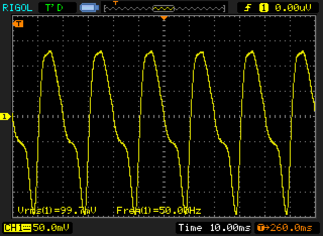
Figure 18.3 - Input Current Waveform With 189mA DC Through Secondary (99.7mA RMS)
Once there was DC in the secondary, the waveform changed dramatically, and shows severe saturation. The waveform is very distorted, and the mains input current increased from 51.5mA to 99.7mA. Since just 189mA DC secondary current from a 28V winding caused the magnetising current to double, you can imagine the current that will be drawn if one is silly enough to try to draw anything even close to the rated current with a half wave rectifier. When the rectifier was rewired as a full wave type, the mains current barely changed, but the output DC increased from 189mA to 388mA (close enough to double).
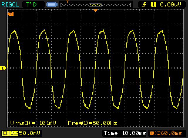
Figure 18.4 - Input Current Waveform Without DC (101mA RMS)
In the above screen capture, you can see that the waveform is symmetrical with a full wave rectifier (note that bridge rectifiers are always full wave). There is no sign of 'uni-polar' saturation, and as described above the load power is increased fourfold for the same input current. The transformer will be much happier, and can be used up to its full rated current.
The same test with a toroidal transformer will give much greater increases with a half wave rectifier, because they have a much tighter magnetic circuit that is far less tolerant of any DC component in the windings. The simple fact of the matter is that no transformer should ever be operated into a half wave rectifier, even at low current. Diodes are so cheap that it's false economy to try to get away with one diode, when another 3 means you have a full wave rectifier and no issues with DC. In reality, this should never be an issue. Bridge rectifiers are standard for almost all power supplies used today, and no-one should use half wave rectifiers for anything. Even where the current is only a few milliamps, it's simply a bad idea.
The autotransformer (or auto-transformer) is a special case, and there are things about this type of operation that don't seem to make sense. Any transformer with a split primary can be used as an autotransformer, and provided the two windings are the same voltage, the output voltage will be half or double the input voltage. Like any transformer there are copper losses which determine the regulation, but otherwise it performs exactly as theory would predict. Or does it?
Before I continue, it must be pointed out that using an autotransformer to power 120V (or 115V if you prefer) equipment from 230V mains may be very dangerous, and is generally to be avoided if possible. Use an isolating transformer instead. It will be bigger and more expensive, but it provides a safety barrier that an autotransformer cannot provide because it consists of one winding with a centre tap. Some 120V equipment is potentially very unsafe if connected to a 230V supply because it may have no earth and in the case of guitar amps, might include a capacitor from one or the other mains terminals to chassis. These are commonly known as 'death caps' amongst repairers because when (not if) they fail the chassis may become live.
An autotransformer has a single winding with a tapping for the output. By varying the turns ratio between the two sections of the winding, the ratio of input to output voltage can be changed. One very common use of a variable autotransformer is the Variac ™, one of the most useful pieces of equipment you can own if you work on power supplies or repair equipment for a living or for fun. These have their own page on the ESP website.
One of the advantages of fixed (as opposed to variable such as the Variac) step-down autotransformers is that they are smaller, lighter and cheaper than 'traditional' dual winding transformers. In many cases this is a definite advantage, especially in industrial control systems where isolation isn't needed and a conventional transformer would add significant cost. This is especially true for high VA ratings, where the improved regulation can also be an advantage.
It's interesting that nearly everyone who writes about autotransformers will tell you that they are smaller, lighter and cheaper, but most don't say why. The reason is fairly simple. Because there is only one winding, the winding window can be completely filled with just that winding, so more turns of heavier gauge wire can be used and therefore the core may be smaller (because there are more turns) and still remain within the allowable range of flux density.
With a conventional dual winding (isolated) transformer, only half the winding window area is available for each winding, so a larger core is needed because the primary winding must still have enough turns, and space is needed for the secondary. In addition, there is the requirement for insulation between the primary and secondary (not necessary in an autotransformer), which also occupies valuable space in the winding window.
You can also use a conventional dual winding transformer as an autotransformer if it has a dual or centre tapped primary. When used like this, you can draw current from the secondary at the same time, provided the total VA does not exceed that for the transformer. For example, a 230V, 200VA transformer has an allowable maximum primary current of 870mA, so you could draw 0.5A from the centre tap (at 115V, so 57.5VA) and a further 142.VA from the normal secondary or secondaries. If the secondary voltage is (say) 60V, you can draw up to 2.375A (142.5VA) from the secondary at the same time. The total from the transformer is still 200VA. The transformer's rated VA must not be exceeded, and all outputs have to be included. This is often a bad idea as the primary current may be exceeded, but it's useful for powering )for example) a 120V fan on a 230V system.
An autotransformer does not isolate the input from the output which makes it completely unsuitable where electrical safety is important, such as fixed wiring or for power tools. Depending on the type of fault, an electrical safety switch (core balance relay, earth leakage detector, residual current device, etc.) may or may not operate if you contact the output of an autotransformer. Claims that they are somehow 'safer' than dual winding transformers are simply nonsense if you happen to come across them (yes, I have seen this claim made, but I'm not saying where because they don't deserve a link. . If safety is paramount, then dual winding (isolation) transformers are better, optionally with an electrical safety switch as part of the installation if permitted by local regulations. Electrical safety regulations worldwide will indicate that dual winding (isolation) transformers are inherently much safer than autotransformers.
You may see autotransformers used for step-up and step-down, but the latter is far more common. The general form of an autotransformer is shown below. I'm assuming a 2:1 transformer here, which might be used to reduce 230V to 115V. If designed appropriately, 115V AC can be applied to point 'B' and you'll get 230V at point 'A' - step-up mode. In that case, input current will be double the output current, and half of the input current flows in each half of the winding (i.e. half flows from 'B' to 'C' and the other half from 'B' to 'A').
Figure 19.1 - General Form Of A Step-Down Autotransformer
Power is delivered to the load by two separate mechanisms, although they are inextricably linked. From the input, 50% of the power is delivered to the load through the upper half of the winding. This mechanism is totally controlled by transformer action due to magnetic flux in the core. So the 'upper' 50% is due to the normal action of a transformer and conduction doesn't play any role at all (despite some explanations that claim the upper 50% is "due to conduction"). The remaining 50% is delivered from the lower winding, also by transformer action. The two output currents sum at point 'B', providing twice as much output current as input current. This means that if we draw 1A from the tapping the current from the mains will be 500mA. Half of the load current is supplied by the upper part of the winding (from A to B), and the other half is supplied by the lower winding (from C to B).
Current from the lower part of the winding is in phase with that from the upper winding, and each winding is supplying current to the load. If you were to examine the current at point 'C' you will see that it's actually 180° out of phase with the current at point 'A'. That shows that the lower winding is supplying current. In effect, each half of the winding can be thought of as supplying current in opposite directions - from points 'A' to 'B' for the upper winding and from points 'C' to 'B' for the lower winding.
This may seem improbable, but it is true nonetheless. Each half of the winding will carry 500mA, and the two add together at the centre-tap to give an output current of 1A. The two halves of the winding are linked by the core's magnetic flux, so they do not appear as two inductances in series as you might expect. The flux linkage is the real secret of any transformer, but it's far less obvious in the case of an autotransformer.
Also, note that the transformer doesn't care whether the load is connected from 'A' to 'B' or from 'B' to 'C' as shown above. The net result is identical, but if the load is between 'A' and 'B' the 115V output is referenced to the active conductor (230V AC) which is a safety hazard. There are other considerations and possibilities as well (such as separate 115V loads across each half of the total winding), but they are generally not useful, can be difficult to calculate, and will not be covered here. As noted in the drawing, the polarity (active and neutral) of the mains and output are critical. For safety, the load must connect between points 'B' and 'C', even though it will work either way!
Where the windings are no longer equal, the output voltage and current distribution between the windings is determined by the turns in each section of the winding. If there are 1,000 turns in the upper winding and 100 turns in the lower winding the step down ratio is 11:1 so 230V input will result in 21V output. It may not be immediately obvious why the step-down ratio is 11:1 rather than 10:1 as you might expect.
That's simple - the total primary winding is 1,100 turns, not 1,000 turns, because the two windings are in series. This is one of the many things about autotransformers that doesn't seem to make sense until you look at it properly. It's worth pointing out that high ratios should never be used with autotransformers. The general recommendation is that anything beyond 3:1 (or 1:3 for step-up) should use a conventional dual winding transformer. A transformer that has a low output voltage but is not isolated from the mains is unsafe - to the point where it should be considered extremely dangerous unless the low voltage is completely internal to the equipment, and not accessible by the user. Even then it may be dangerous if a service technician is unaware that the low voltage winding is at mains potential.
Isolated step-down transformers intended for electrical safety should normally be used to power one appliance or power tool only. Once multiple devices are powered from the same transformer, special rules may apply (for example, the UK has a requirement for isolation safety transformers for building sites, and they must be used as described in their operation manuals).
| Autotransformer | Dual Winding Transformer |
| Single winding per phase | Pair of windings per phase |
| Primary and secondary share same winding | Primary and secondary on separate windings |
| Energy transfer by induction | Energy transfer by induction |
| Load electrically connected to source | Load electrically isolated from source |
| Less Winding material | More Winding material |
| Higher efficiency | Lower efficiency |
The above table shows the general differences between auto and dual winding transformers. It's only a basic list, and most people should never use an autotransformer in any equipment simply because they are intrinsically unsafe. Beware of commercial step-down transformers that do not have dual windings - they are usually easily found for sale at on-line auction sites. If you are looking for a step-down tranny and find one that's smaller and cheaper than others you see, that means it's probably an autotransformer and it should not be used unless you are 100% certain that it can never create a hazard. If used with 115-120V equipment from 230V mains, that level of certainty is very difficult to achieve.
Constant voltage transformers (CVTs) are a 'special' kind of device. They aren't particularly common outside of laboratories and some industrial systems, but they are interesting. These are also known as 'ferroresonant' transformers, because they are designed to be resonant at the mains frequency. A capacitor is used (often on an auxiliary winding) that is designed to make the whole transformer resonant, to minimise the generation of mains harmonics. The core is deliberately run into heavy saturation, so variations of the incoming mains voltage are effectively compressed. The regulation isn't outstanding, but it's usually enough to ensure that the mains supplied to other equipment remains steady.
Figure 20.1 - Saturation, Input & Output Of Ferro-Resonant Transformer
I first saw these used in a telecommunications system, where the tight regulation of the transformer meant that a cheaper power supply could be used. If the mains voltage doesn't change, then you don't need as much headroom in a regulator circuit to maintain good regulation over a wide range of mains voltages. This can reduce regulator dissipation significantly. The regulators used at the time were discrete linear types, with an output voltage of 48V in common with most phone systems. The company I worked for at the time also found out (the hard way) that you can't use a 60Hz CVT at 50Hz.
Normal operation sees the flux density at the maximum possible, and the core is saturated. This is normally something that's avoided because it leads to severe overheating. By making the circuit resonant, the high distortion is reduced considerably, and the total current drawn from the mains is kept to an acceptable level. Because the core runs saturated, acoustic noise may be fairly high, and low-load efficiency is poor. Some are inherently short-circuit proof, as the transformer will switch to 'constant current' mode if overloaded. This can prevent motors from starting normally, so it can be either a blessing or a curse.
There's another catch - being resonant, they are designed for a specific mains frequency. You can't use a 60Hz CVT with 50Hz mains or vice versa. The frequency tolerance is generally less than 1Hz for optimum results. These are not often used any more, because switchmode supplies can provide the same benefits with greater efficiency. I don't propose to go into any further detail other than this brief reference, because very few people will ever see one. You can still buy them, as they can provide very good over-voltage (including mains 'spikes') protection for sensitive equipment, but they're not (and have never been) a cheap solution. A web search for 'ferroresonant transformer' will provide more info for anyone interested in these transformers.
Note: The term 'constant voltage transformer' has two meanings. The primary one is described here, but the term is also used for 70/ 100V audio public address systems (see Commercial Sound - 70V & 100V 'constant voltage' line public address systems. These transformers are not constant voltage, but the term is common in that industry. If you encounter the term, the context is the key to knowing which 'constant voltage' transformer is being referred to.
Use these links for the other sections of this series.
Countless different books and Web pages were researched during the compilation of this article, and although some were interesting, the majority were of minimal use. Of those who I actually remember (a daunting task in itself, considering the sheer amount of searching I had to do), I must pay tribute to the following Web pages (in alphabetical order) ...
In addition, I have used various other references, but notably (in descending order of usefulness) ...
Download Silvio Klaic's neat little transformer calculator from his website
Note that only a couple of references are cited for current transformers, because most I found either provided nothing I didn't know already, were excessively technical but still provided nothing new, or contained inaccuracies/ incorrect information. In general though, you can trust the manufacturers data, as they do know what they are doing.
Units of Measurement site copyright by Russ Rowlett and University of North Carolina at Chapel Hill.
Definitions used with author's permission.
Tesla (T) - flux density (or field intensity) for magnetic fields (also called the magnetic induction). The intensity of a magnetic field can be measured by placing a current-carrying conductor in the field. The magnetic field exerts a force on the conductor which depends on the amount of the current and the length of the conductor. One Tesla is defined as the field intensity generating one Newton of force per ampere of current per meter of conductor. Equivalently, one Tesla represents a magnetic flux density of one Weber per square meter of area. A field of one Tesla is quite strong: the strongest fields available in laboratories are about 20 Teslas, and the Earth's magnetic flux density at its surface, is about 50 microteslas (µT). One Tesla equals 10,000 gauss. The Tesla, defined in 1958, is named after Nikola Tesla (1856-1943), whose work in electromagnetic induction led to the first practical generators and motors using alternating current (much to the annoyance of Edison, who claimed DC was 'safer').
Weber (Wb) - magnetic flux. 'Flux' is the rate (per unit of time) in which something crosses a surface perpendicular to the flow. In the case of a magnetic field, then the magnetic flux across a perpendicular surface is the product of the magnetic flux density, in Teslas, and the surface area, in square metres. If a varying magnetic field passes perpendicularly through a circular loop of conducting material (one turn), the variation in the field induces a electric potential in the loop. If the flux is changing at a uniform rate of one Weber per second, the induced potential is one volt. The unit honours the German physicist Wilhelm Eduard Weber (1804-1891), one of the early researchers of magnetism.
| Main Index
Articles Index
|
