
|
|
| Elliott Sound Products | Project 139 |
The project described in this article is a mains current monitor. The idea was originally suggested by Phil Allison (who has contributed a number of articles and projects), and the article was spurred on by a similar device published in a local electronics magazine. This version is much better than the one published though, because it has far lower noise and has several ranges. The heart of the monitor is a Honeywell CSLA2CD Hall effect open loop current sensor. These are available from RS Components worldwide - part number is 181-2129, and they cost just over AU$40 when I last checked. Several other major distributors also supply the sensors, so just do a quick search. There are quite a few different versions, but the one suggested is most likely to satisfy the greatest number of users.
This device has a linear range up to 72A, and provides a nominal output of 32.7mV/A for a single turn, or 327mV/A for 10 turns. Both are used in this design, but the signal is amplified by ~3 to provide 100mV/A and 1V/A (both are adjustable with preset pots for calibration). An additional x10 range is provided by a second switchable resistor and trimpot (x100 total), giving a maximum sensitivity of 10V/A (or 1V/100mA). The sensor is designed to operate from a nominal 8V supply, and is biased to 4V at the output. In this design, the supply voltage is ±5V - this is well within the maximum supply voltage rating.
At maximum peak current (±72A), the output will vary over the range from 1.64V to 6.35V, and it can measure DC as well as AC. When measuring DC, it is necessary to include an offset control, especially when the x10 amplifier is in use. When measuring AC only, the signal is capacitor coupled to remove any DC component. The capacitor is deliberately large so that 'transient' DC events are still captured accurately.
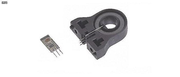
Figure 1 - CSLA2CD Current Transducer
The above photo shows the transducer and the sensor board (I don't recommend that you detach it though). Connected in the circuit described here, you can expect to be able to measure down to a few milliamps easily, and without excessive noise making the oscilloscope display unreadable. The noise on the mains itself will often be the limiting factor, not the current monitor.
As a service tool, a current monitor is almost indispensable, because it allows you to monitor the current drawn by the unit being tested. In conjunction with a Variac (see article), you can tell instantly if the DUT is drawing excessive current, well before you get blown fuses and/ or other additional damage. More to the point, you can do it with complete safety, because the current monitor has an output that's completely isolated from the mains.
A current monitor is also ideal for monitoring a power amplifier's quiescent current. With no load, all amps will draw a small but measurable mains current. If the bias is unstable, the mains current will reflect this, without having to resort to connecting a multimeter with clip leads. Tests can be performed with the amp's cover in place so you get to see if there is any tendency towards thermal runaway with the amp operated normally.
The output can go to an RMS multimeter and/or an oscilloscope. Not only do you see the actual current waveform, but you can also take an accurate measurement. Note that with many products that draw a non-linear mains current, an ordinary (ie. not true RMS) meter will be inaccurate, giving a reading that may be far less than the real value. This is especially true of the typical waveforms you'll see with switching power supplies. Because these current waveforms typically consist of repeated narrow positive and negative spikes, an average-reading meter can easily underestimate the current by a factor of four or more.
Note that this piece of kit is something that you must make for yourself if you decide that you need one. To the best of my knowledge, there is nothing like it on the market. Yes, you can get clamp meters that you might be able to modify, and current probes for oscilloscopes, but the former don't have the versatility of the design shown here and the latter are seriously expensive (and they are limited too). With this current monitor, you can measure and/or view mains current from a few milliamps up to many amps, with peak current measurements over 70A!
For many people, this project will be seen as overkill because the features (and very wide bandwidth) just aren't needed for what you need to do. Not a problem - just go to Project 139a instead. The accuracy and linearity will never be as good as the unit shown here, but it has the great advantage of not needing a power supply, because there are no electronics at all. If this sounds like what you need then P139a is for you. 
As noted above, the CSLA2CD is a Hall-effect device, and uses from 1 to 10 turns (or more if you wanted to) through the ferrite ring. The current through the 'primary' causes a magnetic field in the ferrite core, and the field strength is sensed by a Hall effect device. This is directly proportional to the current in the wire. Adding turns increases the sensitivity, so with 10 turns the output is (nominally) 327mV/A. A single turn allows for a linear peak current of ±72A peak (or 50A RMS for a sinewave), and 10 turns allows for up to ±7.2A peak - 5A RMS. The CSLA2CD draws about 20mA from a 10V DC supply, and the output floats at 1/2 supply voltage. The output from the sensor is amplified by around 3, to give a single-turn reading of 100mV/A and a 10-turn reading of 1V/A. Note that if the current waveform is not a sinewave, you can't estimate the RMS value from the peak - it has to be calculated or measured with an RMS system (true RMS multimeter or digital oscilloscope for example).
By adding the facility for x10 gain (a total gain of about 30 times), the sensitivity is increased further, to ±720mA peak or 500mA RMS (10V/A or 1V/100mA). In each case, the maximum output from the sensor is ±2.35V, referred to the 1/2 supply voltage. The maximum supply voltage for the CSLA2CD is 12V, and this increases the sensitivity to about 49mV/A with a single turn. This gives a useful improvement in sensitivity and therefore requires less amplification (which reduces noise), and I recommend using a slightly higher supply voltage than the suggested 8V (±4V). In the design presented, the supply voltage is ±5.1V. The gain stages use ±12V supplies, and this allows plenty of headroom after the signal is amplified. Maximum output voltage is ±7.2V peak (5V RMS) for full scale on each range. The opamp outputs will limit the maximum peak to about ±10V, or ±100A peak. This is slightly outside the linear range, but will usually be fine in practice.
The gain stage is simple, and can be built on prototype board. The opamp stage operates with either of two gain levels that are set with trimpots, so the unit can be calibrated. The stage operates with DC coupling so that direct current can also be measured. This may be very useful if you are trying to track down noisy toroidal transformers which are badly affected by any mains DC. (See the article Blocking Mains DC Offset.) However, DC coupling is entirely optional. The low frequency response is more than sufficient to allow transient DC events (such as transformer inrush current) to be measured easily, even when AC coupled.
A complete schematic for the unit is shown below, excluding the DC power supply. There are several possibilities for a supply, but the most straightforward is to use Project 05. However, the simple supply shown in Figure 3 will normally be quite satisfactory. The arrangement shown allows you to use a single 12V AC transformer to obtain the required ±12V for the monitor. As seen in the circuit diagram, the ±5.1V supplies are derived from the main supplies, and they use simple zener regulators. In use, the transducer supply voltage will stabilise quite quickly and it benefits from the regulated main power supply.
The advantage of the arrangement shown is that all voltages are (more-or-less) completely symmetrical around the earth reference. A simpler supply circuit could have been used, but would need level-shifting to allow DC to be measured. This makes the circuit more complex, and also makes it harder to apply DC offset so that measurements can include any DC component.
Figure 2 - Full Schematic Of The Current Monitor
The circuit shown above includes all the options. If you don't need to measure 'actual' DC, the DC offset control isn't critical, but it is still recommended if the x10 gain option is included because the opamp's output may be offset by 1.5V or more. A 'minimalist' version is shown below, and shows the circuit without the DC option and switchable filter, but including the DC offset control. The 100kHz filter shown is also optional, but is useful to reduce broadband noise. The AC section is not repeated.

Figure 2A - 'Minimalist' Version Of The Current Monitor
There really isn't a great deal involved, and it's easily wired on Veroboard or similar (see the photo of my unit below). Make sure that you double check the sensor connections against the datasheet - the view in Figure 2 is from the bottom, but you need to be absolutely certain that you get the connections right. If you get the +ve and -ve connections wrong you are likely to damage the sensor. Likewise, make sure that the opamp supplies are correct or the magic smoke will escape.
Please Note: The DC offset control has been modified, because as originally shown it would correct for offset from the opamp, but not the sensor. With the new arrangement shown above, you can correct for up to ±120mV offset from the sensor. This should be more than enough, provided the two 5.1V zeners are fairly well matched. This problem slipped through because when I assembled and tested my unit, the offset was minimal. My apologies to anyone who had problems with it as it was. Note that if you don't plan to use the monitor with DC and don't need the opamp x10 gain switching, there is no need to bother with the offset, as it's removed by the output capacitors (C3 and C4). Because of the high gain when set for x10 gain, the DC offset control is still needed, but it doesn't need to be set particularly accurately (±100mV or so is quite alright). The DC offset will otherwise be adjusted so it's no more than ±500µV or better (depending on your application).
WARNING
The wiring for the lower half of the schematic shown in Figure 2 operates at mains voltage, and may be lethal if touched. All mains wiring must be performed by a suitably qualified person, using cable that is rated for mains voltages. It may be an offence where you live to perform mains wiring if unqualified. Wire diameter must be adequate to ensure that there is no possibility of overheating if the current monitor is used with the maximum available current.
The 1 and 10 turn coils shown are wound through the hole in the sensor, in the same way as if you were winding an inductor. The single turn coil simply passes through the centre - it makes no difference if the coil is open or closed outside the ferrite ring. The 10 turn coil requires exactly 10 turns, where a 'turn' is defined as the wire passing through the hole. Anything on the outside of the ferrite ring doesn't count, but all turns must be in the same direction of course. (See Figure 4.) When the 10 turn option is used with the x10 gain stage (as shown around the opamp) the total gain is 100 - so a mains current of 10mA will provide a 1V output. This may be useful for measuring very low power devices (10mA at 230V is 2.3VA).
The two 1N5404 diodes (D3, D4) are to prevent a break in the supply if/when you change ranges. The voltage across them will normally never be sufficient to cause conduction, except for the brief period when the range switch is changing between the two primary windings. Depending on the load, a very high current may be drawn if the mains is interrupted briefly, and the diodes prevent this from happening. You can also use a bridge rectifier (preferably 10A) with the +ve and -ve terminals shorted, which provides 4 diodes in a series/parallel circuit.
Both the range and power switch must be rated for at least 10A (20A in 120V countries), and also must be suitable for mains use. Don't even think of using mini-toggle switches - they can't handle the current and are also unsafe because they don't have good enough isolation between live parts and the metal switch body or toggle. You can use a mini-toggle to activate a relay though - that's what I did in my unit.
The gain stage is straightforward, and can use pretty much any single opamp that you have available. I've suggested the TL071 as a good general purpose opamp that has fairly low DC offset. The DC offset control (either as a front panel knob or internal trimpot) is only needed when you need to measure DC. With a 100k resistor as shown for R2, that gives a range of ±120mV at the input of U1. If offset cannot be reduced to zero with 100k installed, reduce the value of R2.
When set for AC (switch open), the offset control doesn't do anything useful. If you don't think that you'll need DC coupling you can omit the AC/DC switch. I suggest that you retain the DC offset control, but it can be an internal trimpot. The circuit deliberately has quite a long time-constant, so 'transient DC' events will still be clearly visible on an oscilloscope even when used with AC coupling. This is at the expense of settling time - the current monitor will need about 1 minute to stabilise after the power supply is turned on. The sensor may take a bit longer to stabilise, so allow about 10 minutes before you adjust the offset to zero.
Note that if you measure a high current DC using this sensor, you may partially magnetise the core and that will create a DC offset. In general, avoid using the current monitor with DC if at all possible. The DC capability is included only so you can measure DC offset in the mains - it's not so you can measure DC in isolation (such as from power supply outputs).
Whether you use the filters or not is optional. For most applications, a bandwidth of 10kHz will be more than enough, and that's accomplished by means of a simple 6dB/octave filter at the output of the transducer. R1 and C1 form the filter, and you can include a switch to change the bandwidth from 10kHz to 100kHz. The filters aren't exact, but are close enough for this application. If a centre-off switch is used you can retain full bandwidth (which may be limited by the opamp at maximum gain).
If desired, you can hard-wire the filter at the required frequency, or they can be omitted. There's a small noise penalty with no filters, but it's unlikely to cause problems except at very low current. Naturally, you can change the capacitor(s) to get different filter frequencies. The normal resistor/capacitor filter formula applies ...
C = 1 / ( 2π × R × f )
where C is capacitance in Farads, R is resistance (1k) and f is the -3dB frequency in Hertz
For example, if you use a 100nF capacitor, the filter will give a -3dB frequency of 1,590Hz - a bit too low for most applications. However, if you only need to see the 50/60Hz current waveform and don't care too much about upper harmonics, a low cutoff frequency means that you can look at very low currents with minimal noise.
Using a traditional linear power supply will give very good results. The benefit of this is that there is no high frequency noise that you'd get using a switchmode supply. The noise from a SMPS can be very difficult to remove, it will show up on your oscilloscope trace all the time, and makes accurate measurements (especially at low current) very difficult. The supply shown is based on the original version of the P05, or you can use the latest version with adjustable regulators. You can increase the voltage to ±15V if you wish, but you need a transformer with ~16V AC output, and you'll have to change the value of R7 and R8 (increase to 180 ohms, 1W). The current transducer will be well outside its linear range at maximum output voltage (typically around ±14V or 140A at minimum sensitivity) so there is no good reason to use the higher supply voltages.
Figure 3 - Power Supply Schematic
If you plan to use the monitor in conjunction with a Variac, you will need two incoming mains leads. At low voltages from the Variac, the power supply won't provide enough voltage and the circuit won't work, so you need a second mains connection (or the wall transformer) that is connected to the mains normally (without the Variac). This ensures that the circuit is fully operational regardless of the voltage from the Variac to the device being tested. The main filter caps (marked with *) are shown as 1,000µF, but you can use anything up to around 2,200µF if you like.
Before calibrating the current monitor, you first need to trim the DC offset. Set the output for DC coupling (switch closed) and x10 gain for the second preamp, apply power and allow a few minutes (more is better) for everything to stabilise. Carefully adjust the DC offset control (VR3) until the voltage at the output reads as close to 0V as possible. Reduce preamp gain to x1 and verify that the output remains at 0V. There may be a small amount of drift over the first 30 minutes or so - re-test and adjust as necessary.
To calibrate the current, you'll need a suitable current source that can supply at least 100mA AC. I suggest using the output from a transformer and a suitable dummy load, such as a 25V transformer and a 220 ohm 5W resistor. You also need two accurate multimeters (preferably true RMS) as references. Wire the transformer secondary, 270 ohm resistor, one multimeter and current sensor coil circuit in series, with the multimeter set to the correct AC current range.
Set VR1 and VR2 to roughly half resistance to start with. Connect the second multimeter (set for AC volts) to the output of the monitor. With the unit set for x10 range (10 turn coil) and x1 preamp gain, adjust VR1 until the output voltage from the current monitor shows exactly 10 times the reading shown on the multimeter. For example, if the multimeter shows 0.110A, the output from the current monitor should be 1.10V. Next, switch over to the 1 turn coil (x1), and switch the monitor to x10 preamp gain. Adjust VR2 until you get the same reading again (check against the current measuring multimeter in case the mains voltage has changed).
If you included the DC option, calibration can be done using DC instead of AC. This is likely to be more accurate (the DC ranges are usually more accurate that AC ranges on multimeters), and you don't need meters with true RMS. Any DC power supply and suitable load resistor can be used, and again you are aiming for around 100mA. Otherwise, the process is virtually identical to that described above, except that all measurements are DC, not AC.
Double check all settings and adjust carefully as needed until you are satisfied with the calibration. Once this is done, the unit can be fitted into a case.
Make the case ready, adding a mains outlet, switches and combination binding posts for the output. Incoming mains lead(s) can connect using fixed leads or IEC sockets. Remember that if you plan to use a Variac, the current monitor's power supply must have its own power lead. In this case, do not link the two mains connections - the lower part of Figure 2 is a completely separate circuit and is only for measurement. Note that power supply wiring is not shown below for clarity. Needless to say that the +ve, -ve and earth connections must be run from the power supply to the preamp board. Don't attempt to reproduce the layout of the preamp in the drawing - it is conceptual, and is intended only to give you the general idea.
Make sure that the transformer (if an internal unit is used), all Veroboard and/or other PCBs are properly mounted and permanently connect all wiring. Make sure that AC mains wiring is safe, that there are no live mains connections that can be touched, and that none of your wiring can come adrift. Make sure that you heed all local/country specific requirements for mains wiring!
Figure 4 - Suggested Internal Layout (Concept)
Shown above is a suggestion for the internal layout. I've assumed that the current monitor will be used in conjunction with a Variac, so there are two mains leads. The test circuit lead can be fixed or may use an IEC connector, as can the power supply lead. If you don't have a Variac (and don't plan to get one), only a single mains lead is needed. This may be fixed or you can use the IEC socket. Note that 'A E N' stands for 'Active (Line), Earth (Ground), Neutral'. The Earth lead should be securely fixed to the case as shown.
The wiring shown is merely a suggestion, but the mains wiring should be followed fairly closely. You will see that all mains wiring is separated from the low voltage circuits, and is cable tied to ensure it can't go anywhere that may cause a problem. The two 1N5404 diodes and the back of the coil switch should be insulated with heatshrink tubing or similar, along with any other exposed live connections.
The single and 10-turn windings through the transducer must be wound with mains rated cable. Neatness is not essential - only the number of turns is important. Wiring can be fixed using cable ties when the coils are wound, and that will stop them from trying to escape (which will happen if they are not restrained).
I suggest that you use a standard mains outlet - either a single wall-plate or a surface mount outlet that is designed for the standard mains plug used where you live. There are many different styles, and I'm unable to cover them all. Some may be more user-friendly than others. Note that you must use an outlet that includes protective earth (where there is a choice), and that the incoming mains is also earthed to the case and outlet socket.
While it's not uncommon for experimental circuits and test fixtures to be somewhat ... shall we say 'avant-garde' compared to consumer products, there's no point making a test unit that tries to kill you every time it's used. This current monitor will commonly be used as a matter of course whenever you are testing anything, and it will show you immediately if something is wrong and drawing excessive current. The next step would be to add a true RMS detector and a LED or LCD panel meter so you have a permanent readout of the current drawn by anything you are working on.
Double check your wiring, then retest the current monitor once it's fully assembled in the case.
You now have a very useful piece of test equipment. It is unlikely to be used every day (unless you are servicing equipment or just love testing things), but you'll probably wonder how you got along without it when the time comes. If it semi-permanently wired in as part of your test bench you'll find yourself using it whenever you are working on any mains powered equipment.
It's especially educational to observe the mains current waveform of different loads on an oscilloscope - you will be surprised at some of the things you see. You'll quickly discover that the vast majority of mains operated equipment (at least anything with a power supply) draws a very distorted current waveform.
Having presented all this info, it would be remiss of me not to show you the innards of my unit, along with a few sample measurements. This includes examples of the difference between my digital oscilloscope (which calculates the true RMS value), a true RMS bench multimeter and a 'conventional' average-reading, RMS calibrated meter. This can't be ignored, because the difference can be significant with non-linear waveforms. As a test load, I used a 5V/1A plug-pack switchmode supply. As shown below, my current monitor gives a very good account of itself when measuring an RMS mains current of only 3mA. Yours will do the same if built as described.
Pictures are always interesting, so here is an interior shot of my monitor that help to illustrate the general construction. Mine has an extra feature, in that I included a voltage output as well. This is used primarily to show phase angles for loads with lagging or leading power factors, but it's not essential unless this is something you really need to be able to capture. The voltage output is taken from the transformer secondary via an attenuator. In case you are curious, yes, the transformer is way too big, but it was one I had to hand and it had the right voltages, so was much cheaper than buying one. A 10VA transformer will normally be quite sufficient to power the monitor. I also used a simplified power supply, but I do recommend the fully regulated split supply shown above as it will give better results than my simplified version.

Figure 5 - Interior Photo Of ESP's Current (and Voltage) Monitor
You can see the voltage monitor terminals and calibration pot on the bottom right, and you can also see that I used mini-toggle switches! However, they operate at low voltage and the sensor coils are switched using the relay you can see on the board. Feel free to do the same if it makes your wiring easier or if you simply feel better doing it that way. The relay simply replaces the coil switch, so there is nothing difficult about it. You can also see that I've used the "do as I say, not as I do" approach, in that there are accessible live termination points. Please don't follow my lead - I've been doing this stuff for over 50 years and I take shortcuts for equipment that only I will ever use (the unit does have a cover though. ) The pink wiring for the mains might not look much, but that's Teflon coated wire - you don't have to use anything quite so up-market, but I have a roll of it so ...
Where things get really interesting is when the measurements from my oscilloscope, a true RMS meter, and a 'normal' meter are compared. I tested the power supply both unloaded, and loaded with 8 ohms (625mA DC output at 5V - 3.125W). The readings are tabulated below.
| Load | Scope Volts | Scope Amps | RMS Volts | RMS Amps | Meter Volts | Meter Amps |
| None | 33.3 mV | 3.33 mA | 32 mV | 3.2 mA | 11 mV | 1.1 mA |
| 8 Ohms | 388 mV | 38.8 mA | 370 mV | 37.0 mA | 155 mV | 15.5 mA |
The true RMS meter reads a little lower than the digital oscilloscope simply because it has a restricted bandwidth (around 2kHz maximum). When I applied a 2kHz low pass digital filter to the oscilloscope, I obtained almost identical readings. As is quite obvious, a standard (non-true RMS, indicated by italics) meter seriously underestimates the reading, showing less than half the actual value.
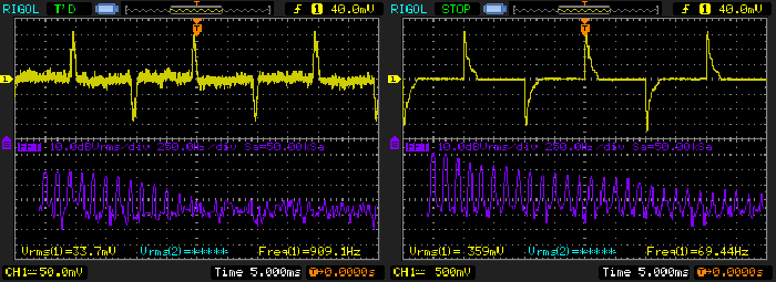
Figure 6 - No-Load And Full Load, Current Waveform And Harmonics
The no-load waveform is on the left, and at the time the reading was taken you can see that the RMS voltage displayed is 33.7mV (3.37mA) with the current monitor set for maximum gain (1V/100mA). The harmonics are a direct result of the wave shape - it's just a series of spikes, each measuring ±150mV (15mA peak). At an output load of 625mA (3.125W), the current spikes reach ±1.6V (160mA peak). Of interest (but not part of what the current monitor can do), the no load (real) power was measured at 0.31W, and loaded power was 4.72W.
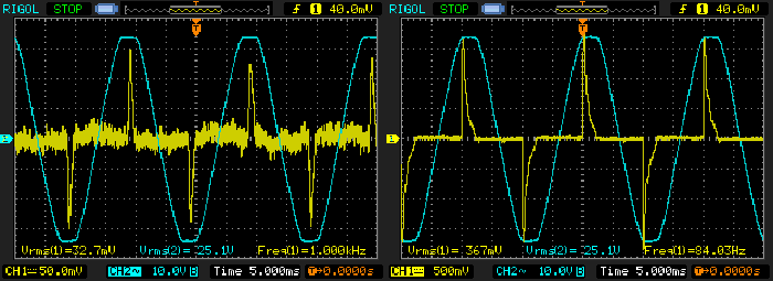
Figure 7 - No-Load And Full Load Current And Voltage Waveforms
Here you can see the relationship between voltage and current. When discussing power factor (which is dreadful), the traditional concepts of 'leading' or 'lagging' phase angles are irrelevant, because the waveform is non-linear. For what it's worth, the loaded power factor is 4.72W / 8.88VA = 0.53. This is quite typical for small switchmode supplies, compact fluorescent lamps and many of the cheap LED lamps that are now available.
As an aside (and because it's something I really wish that some people who should know better would at least try to grasp), the concept of lagging or leading power factor does not apply with a non-linear load. A leading or lagging power factor is the result of a reactive load, which means that current and voltage will have opposite polarities at some part of the waveform. If this doesn't occur, the load is not reactive, and leading/ lagging power factor cannot occur!
In short, this is a very useful and versatile piece of test gear, and is particularly well suited for use while repairing and testing equipment. It is also fascinating to examine the mains current drawn by different types of power supplies. Best results will always involve an oscilloscope. You can also examine transformer inrush current (both with and without a rectifier and filter caps on the secondary), and you can even see the current surge drawn by a conventional incandescent lamp. The current waveforms this will show you are not normally seen in test results, and it can really assist your understanding of the way that different power supplies interact with the AC mains.
 Main Index
Projects Index
Main Index
Projects Index