
|
| Elliott Sound Products | Beginners' Guide to Transformers - Part 3 |

 Main Index
 Articles Index
In this section, we will look at taking measurements from existing transformers to assess their ability to be re-used, some basic calculations usable for transformer design (thanks to Geoff Sevart) and look more closely at power supply analysis (thanks to Martin Czech). In all, there are three different programs that you can download and use presented here. It is also highly recommended that you use a good simulator to verify the final design - as always, I suggest SIMetrix. Before simulating, you will need to know the parameters to build the equivalent circuit - see section 2 for more information on this topic.
Transformer analysis largely involves determining if a given transformer will provide a level of performance that meets your design goals. Three completely different approaches are provided here - one is an executable program that provides a fairly accurate assessment of the transformer's performance based on a few measurements that you perform.
The other is a Microsoft Excel spreadsheet that does much the same thing. The main difference is that the spreadsheet does not have an on-line help facility, so all instructions are provided here (as well as in a 'readme' file included in the compress archive).
Finally, the third program can be used to reverse engineer a transformer, or to design one that meets your needs. Only the basics are covered, and you need to be well versed in the requirements for insulation (both inter-winding and intra-winding). You may also need to know the details of the steel used - assumptions are not always valid. Remember that in all cases, it is your responsibility to ensure that the design is safe (or remains safe if you modify an existing transformer).
There are some differences in the way the three analysis processes work, and it is up to you to decide which one is most suitable. None is intended for beginners or those with an aversion to taking measurements and experimenting - these are all serious tools to allow you to analyse or determine the suitability of any given transformer.
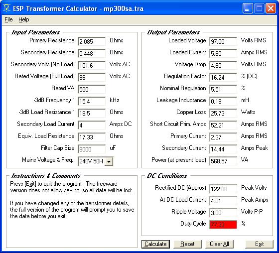
The transformer analysis program (xformer.exe) can be downloaded from the Downloads page or from the downloads section of this page, as a zipped archive. It has very extensive help facilities, and is complete with test circuits, a transformer equivalent circuit (with all explanations), and the complete sequence to evaluate an unknown transformer. It will provide the DC output at the specified load, and includes duty cycle calculations so that you can see what happens when the transformer is overloaded.

Figure 1 - Screen Shot of XFORMER.EXE
The box marked 'Instructions & Comments' is context sensitive, so it will display relevant information based on the current mouse position. To find out more about any parameter, simply position the mouse over the text box or its adjacent label. A great deal more information is available from the help screens.
As with any program, there will be some variation between what it claims and reality, so the measured values will not always be in complete agreement with those calculated. There is only so much that can be conveniently determined, but the results will be close enough for almost all applications. Where extreme accuracy is needed, you will have to build the circuit to verify exactly what it does, however the very nature of a power supply is such that accuracy is not normally a major issue.
The program uses SI units only, and assumes a dual polarity full-wave bridge rectifier (conventional ± amplifier type power supply). At this stage, no other supply types are available, and probably will not be added because the default is suitable for most applications. In normal use, a single supply is still easily tested. You will need to experiment with the program to find out if it does exactly what you need.
2.2.1 - Purpose
This Excel spreadsheet is made for convenient 'linear PSU' design. This is a PSU made using a transformer, rectifier diodes and filtering capacitors. The load presented to the PSU is a resistor. The sheet was tested against SPICE simulations and has shown accuracy to about 2% or better.
However, since not all possible configurations can be checked it should always be verified by a subsequent SPICE simulation.

Figure 2 - Partial Screen Shot of TRAFO7.XLS
2.2.2 - Assumptions
This Excel spreadsheet tries to model the nonlinear behaviour of such a PSU with simple equations and estimations. The transformer is modelled as a non ideal voltage source, i.e. an ideal voltage source plus series resistance. It uses only SI units (m,A,V, Ohm, etc.).
Four common circuits can be calculated ...
Usually a given transformer is specified with Uneff (effective value of secondary voltage under full resistive load, and Pn (nominal output power with said resistive load) and loss factor f (ratio between U0eff and Uneff, U0eff being the effective value of output voltage with no load), and of course the primary effective voltage Unetz.
I.e.: U0eff = f × UneffOut of Pn and Uneff we get the load current In (In = Pn / Un). The series resistance is therefore
( U0eff - Uneff ) / Ineff = ( f × Uneff - Uneff ) / Ineff
= Uneff × ( f - 1 ) / In
= Uneff × 2 × ( f - 1 ) / Pn
the latter is convenient because it uses only the usually given parameters. This applies also to transformers with several identical coils. It does not apply for additional auxiliary windings and taps, which can have lower power spec and therefore more series resistance than perhaps expected.
The sheet works for one coil or two identical coils, due to the symmetry of the circuit and load situation the same current and voltage values will appear. Therefore they are only given once in the sheet.
Sadly, f (loss factor) is not given by many vendors. So the spreadsheet has some heuristic formula to determine f out of the transformer total power rating. This works from about 5 VA up to 1000 VA. This is no big science, but relates to the usual tradeoffs when winding transformer coils. The value is valid for toroidal types, f is often lower for EI types. However, if you can obtain a data sheet with f, then do not use the heuristic value.
The spreadsheet does also include mains voltage variation. In central Europe this is tending to +-10% of the nominal value, guaranteed at the house main power entry. Some additional wiring can be added to that (be it house installation or additional cables, perhaps during live shows). The transformed total mains resistance will simply add to the transformer series resistance.
The remaining interesting part of the formulas is derived by approximating the voltage sine waves with parabola, in order to get any analytic result. Unfortunately the resulting nonlinear equation can only be solved by program, I used an iteration approach in this Excel sheet.
The load is assumed to be a resistor. In reality this not always the case. Some circuits tend to be constant current drains (regulator plus electronic circuit). Others have variable current consumption (power amplifiers), but also there the current does not depend on PSU voltage. A starting point for the later cases is to make the delivered output power equal, i.e. choosing the output current and resistor in that way.
2.2.3 - How to do it
The Excel sheet has a yellow title range. Below that on the left hand side we find explanations to the parameters, the salmon colored column shows the parameter name. The next column is commonly used for all four possible circuits, the next four columns carry the results and entries for each circuit individually.
Anything shown below in italics indicates that it is a field in the spreadsheet.
First you have to enter data into the white common fields. Each field must be filled. Most of this is very easy. You enter ...
Usually alpha is chosen to be 1.5 ... 2, even large over dimensioning is possible with modern toroid types, because idle losses are still low.
Imax >> In means that in this PSU the peak current is much larger than in the situation where the transformer drives only a resistive load to the rated power. One should compute the RMS value from simulation to estimate the loss. Based on that choose alpha to be higher.
You are done with the common data. Now you can decide which circuit column you need to use. It is only necessary to fill in that column, but it is also possible to use several or all in parallel for study or comparison.
Now the Excel sheet knows the output power [Pa], nominal power per coil [Pns], and the total nominal transformer power [Pn]. The heuristic formula can therefore suggest a value for the toroid loss factor [f]. If you have no better data, enter this value in the white field 'actual transformer loss factor'. Now you have completed all white fields, you are nearly done.
In the last step you solve the nonlinear equation by manual iteration. You enter a nominal coil voltage [Uneff] (pink field) and change it, until the relative iteration difference [r] (light blue) is 0.0% (or near to that). In this case the single coil output voltage under load with infinitely large capacitor [Ua8] will match the iterated single coil output voltage [Uaber] (darker blue).
Now you have solved the equation, but is the worst case voltage [Ua-] as expected? You should compare this lowest per coil output voltage under load [Ua-] with your intended desired minimum nominal output voltage [Uaminn]. If [Ua-] is too low, the circuit will have too low voltage in case of low mains voltage, a longer than expected cable can add to that.
This makes perhaps no difference for a power amp, since a few % amplitude loss is not audible. In the case of a subsequent voltage regulator a too low voltage will simply mean loss of regulation with perhaps additional artifacts, this is clearly not acceptable. Give more [Uamin] in such a case, and iterate again.
Take care: this can influence the power, so the current [Ia] may need some adjustment, too. Finally power change can change loss factor [f], so this has also to be adapted. If the initial guess was good enough, little or no modification needs to be made on that side.
So now you are done. You should take the relevant data from the sheet (U0, Un, Pn, f) and do a SPICE simulation to verify. A second computation is always good, since you are going to spend a lot of money for a PSU!
2.2.4 - What else does the sheet tell you
It not only tells you Uneff, Pn, f, Unetz to order your transformer, it also tells you the size of the filter capacitors Cl, and Ua0+, this idle output voltage plus tolerance tells you about the voltage stress these and other devices connected to your PSU have to take.
Imax is the periodic peak current in the transformer windings and diodes, so it will tell you something about fuse stress and diode stress, as well as capacitor ripple current.
The total rectifier loss power Pg and the maximum diode reverse voltage Usper+ will also help to buy the right rectifier.
All the devices need not only cope with the rated voltage stress, but even more has to be considered because of possible mains transients. A factor of 2 over dimensioning is not too expensive in most cases, an exploded cap or whole PSU plus circuit certainly is.
If your output voltage is so high that voltage over dimensioning is not possible, primary side varistors should be used to handle transients. They should be used anyway.
2.2.5 - Explanation of Parameters
The parameters used in the spreadsheet are listed here. Although some of these may appear daunting at first, it is not difficult to figure out what they are all for. Note that the derivation of some of the terms is directly from German (netz = mains, for example). Many of the parameters used are fixed - there is no need to change them once they have been set for local conditions - examples are mains voltage and frequency, upper and lower tolerances, etc. The line length applies only if there is a significantly long extension lead used, such as setup in an auditorium where a nearby power outlet is not available. For most applications this may be set to 1 (metre) with little loss of accuracy.
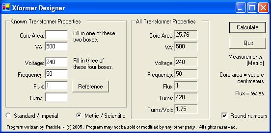
This next program is thanks to 'Particle' otherwise known as Geoff Sevart. With this, you can either analyse or design a transformer, although for proper design work you need to know a bit more than the program provides from its interface. Although fairly simple, it does give good results if you know what you are trying to achieve, and know some of the basics of the core material.

Figure 3 - Screen Shot of TRANSFORMER CALCULATOR.EXE
The screen shot above shows the complete program interface. You insert your known data into the section on the left side, and all calculated values are shown on the right. You need to input either the core area or the VA rating of the transformer, but not both. When that is done, you enter any three of the four remaining fields ...
* Click the 'Reference' button for hints. Typical power transformers will operate at around 1 Tesla. Higher flux density means the core is likely to saturate and be noisy, lower flux makes a mechanically quiet transformer, but at the expense of efficiency. Low flux density is essential for audio transformers, as even approaching saturation can cause high distortion levels.
If your transformer allows you to add some temporary turns, you can determine the number of turns/volt by adding 10 turns of thin insulated wire. Apply power to the primary, and measure the mains voltage (very carefully!). Now, measure the voltage across your extra 10 turn winding. If (for example) you measure 3.3V AC, that means the transformer has ...
TPV = Turns / Voltage = 10 / 3.3 = 3 Turns Per VoltFrom that, you can calculate the number of turns on the primary, using the measured applied mains voltage (assume 230V) ...
Tp = Vp × TPV = 230 × 3 = 690 turns
This figure may be used instead of the assumed flux density, and you will then know the actual flux density being used for the transformer you are testing.
When you click 'Calculate', the program shows the following calculated values ...
Although it may be more difficult using metric calculations as a matter of course, it is highly recommended that you do so anyway. There is nothing in the imperial system that actually makes any sense, so it is far better to use metric whenever possible.
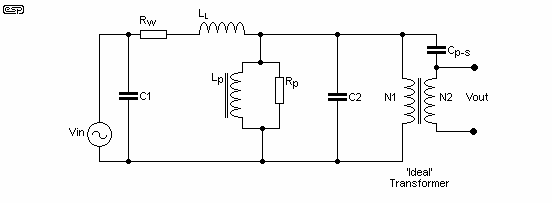
The equivalent circuit shown in Figure 4 allows you to see where the main losses occur with any transformer. The lumped parameter model is the most commonly used, as it gives a very good representation of a real component and is easy to manage for almost any normal load or signal.

Figure 4 - Transformer 'Lumped Parameter' Equivalent Circuit
For most measurements in electronics, a multimeter is all you need. This is not good enough and will become inaccurate when working with transformer winding resistances. Because very low resistances are to be measured, few multimeters have a useful low ohms range. To get sensible results, the measurements you take must be accurate. Very low resistance is always hard to measure, and it can only be done using DC. Many very low ohm meters use AC, but this will give large errors because of the transformer's inductance.
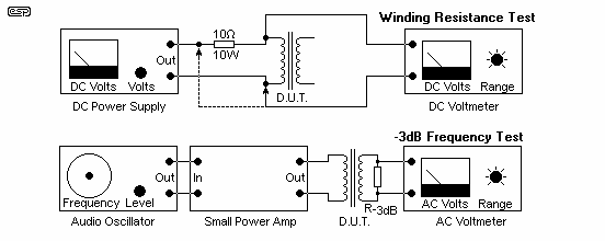
The easiest way to measure a very low resistance is to inject a known current, and measure the voltage across the device under test. For example, if you subject a transformer winding to (exactly) 1A DC, and measure 448mV across the winding, its resistance is 0.448Ω. A regulated DC supply and a 10 ohm 5W resistor is ideal for this. Measure its value carefully - if it measures 10.1 ohms, then 10.1V dropped across the resistor means the current is exactly 1A. This is shown in Figure 5.

Figure 5 - Measuring Very Low Resistance & Leakage Inductance
Figure 5 also shows the basic method for measurement of leakage inductance. The load resistance across the secondary is determined by ...
R-3dB = VS / (VA / VS) Where R-3dB = Test resistance, VS = Secondary Voltage, VA = Volt-Amp RatingSo for a 300VA transformer having a rated total secondary voltage of 70V ...
R-3dB = 70 / (300 / 70) = 70 / 4.3 = 16Ω
Note that this does not have to be extremely accurate, as it is only designed to provide a representative load. This value is only used in the first program shown (TRANSFORMER.EXE), and it is used primarily to determine the transformer's short circuit (fault) current. Leakage reactance can then be determined using the -3dB frequency and the load impedance. Leakage inductance is also useful to know as a comparative figure, allowing you to make meaningful comparisons between different transformers. Transformers with high leakage inductance will inject noise into adjacent circuits, and generally have poorer regulation when high peak currents are expected.
With the programs and spreadsheet detailed here, you have an excellent range of tools at your disposal to ensure that the power supply for your latest masterpiece is as good as you can get it. At last, it is possible to easily analyse an existing transformer, work out just how well (or badly) a given transformer will work in the intended circuit, or even design your own transformer from scratch.
The performance of a transformer when loaded by a diode bridge and capacitor input filter (99% of all power supplies used) is never as good as we might hope or imagine, and these tools will allow you to predict how the supply will behave. By comparing the performance of the final supply with the predictions, you will find that there is fairly good correlation - certainly well within the accepted mains tolerance.
These downloads are free for personal use. They may be re-distributed, but no fee is to be charged for the software. No part of the software may be de-compiled, reverse engineered or used in any way contrary to the general principles of free software distribution. Program copyright belongs to the author of the program. No warranty is expressed or implied - the programs and spreadsheet are provided 'as is', and no responsibility is accepted by the authors for any damages howsoever caused. It is the wholly the users responsibility to determine the validity of the calculations.
All programs are tested and checked and are believed to be free of any computer virus or other 'malware'. It is the user's responsibility to scan all files to ensure that they have not been corrupted or infected.
Various support files needed may or may not be available on your PC, and if not, you will need to obtain them so the programs will run. Full details of the necessary files are shown below for each program.
Click TRANSFORMER1.ZIP (or right click, and select 'Save [Link] Target As ...' ) to download the zipped archive for the program.
Click TRANSFORMER2.ZIP (or right click, and select 'Save [Link] Target As ...' ) to download the zipped archive for the spreadsheet. Make sure that you read the file 'readme.txt' - this is a plain text file, and contains a full description of all fields used and their meanings.
Click TRANSFORMER3.ZIP (or right click, and select 'Save [Link] Target As ...' ) to download the zipped archive for the program.
Use these links for the other sections of this series.
 Main Index
 Articles Index