
|
|
| Elliott Sound Products | Transformers For Small Signal Audio |
 Main Index
Articles Index
Main Index
Articles Index
Using a transformer in a small signal audio circuit is a simple process, and at first glance there is nothing that can go wrong. The term 'small signal' is used to differentiate between transformers used for so-called line level applications and those used to drive speakers (for example). Indeed, in many cases everything works as it should, but there are some traps for the unwary. Common issues may include high distortion at low frequencies, grossly accentuated bass response, little or no bass, or a combination of problems.
The casual experimenter may think that audio transformers are a thing of the past, but this is definitely not the case. Transformers have unique attributes that cannot be matched by active circuitry. Even though there are some extremely good electronic interfaces, none provide the exceptional characteristics that come with a transformer. These include ...
Obviously, transformers have their fair share of negative attributes too. The imperfections are primarily due to the fact that real world materials are used in their construction, and like all real materials they are imperfect. The main issues are ...
Despite the limitations, transformers can do a very credible job of isolating signals from hostile environments, impedance conversion and converting unbalanced signals to balanced and vice versa. Nearly all valve (vacuum tube) amplifiers use a transformer to reduce the relatively high impedance of the valve plate to something useful for driving speakers, and high quality microphone preamps and mixing desks either use mic (and/or line) transformers as a matter of course or offer them as an option.
However, there are various ways (exciting or otherwise) where you can run into trouble. There are equally novel ways that you can use to bypass the limitations of even cheap transformers and it may even be possible to make a silk purse from a sow's ear (no, not really - just kidding.  )
)
As noted earlier, this article is focussed on 'small signal' audio transformers, such as those used for microphone preamps, line level input and output applications, and as signal isolators. By definition, 'small signal' refers to transformers that are typically rated for impedances between 50 and perhaps 10kΩ, and used with voltages from a few millivolts up to about 10V (RMS), and covering the normal audio bandwidth. This is usually taken to be from 20Hz up to 20kHz, but it's not uncommon to extend this in both directions - say from 10Hz to 40kHz - allowing an extra octave either side of the audio band. They are not used at significant power levels, and the maximum will be a few milliwatts.
One of the 'reference' levels is dBm, defined as 1mW at an impedance of 600Ω. This equates to a voltage of 774.6mV, which is normally rounded to 775mV. dBu is a reference level based on 775mV RMS, but without specifying the impedance. dBV is 1V RMS, and again no impedance is stated.
A transformer is defined first and foremost by its turns ratio, which is equal to the voltage ratio from input to output. In some cases, a transformer that's classified as 1:1 may actually be around 1:1.1 to account for insertion loss - that energy that doesn't get through the transformer due to losses. The main source of loss is the resistance of the windings, and the insertion loss will usually be specified (assuming that it is specified) at 1kHz.
Low frequency performance is determined by the transformer's inductance, signal level and the source impedance. A transformer intended for high impedance use requires a much greater inductance than one intended to be driven by a low impedance source. The core material and size is also very important, as these determine the voltage and frequency at which the core will start to saturate. Core saturation causes distortion, and for this reason it is usually extremely important to ensure that there is little or no DC flowing in the primary or secondary, as this will cause asymmetrical core saturation.
As the core approaches saturation, distortion rises dramatically. At low frequencies in particular, maximum signal level, source impedance and distortion are interdependent, and cannot be categorised separately. Because of this, they must always be examined together. Should a data sheet discuss any one (or two) of these parameters in isolation, the data are meaningless and the actual performance must be determined by measurement. However, there are still traps for the unwary, with some than can be used to advantage.
Interestingly, if you drive an ideal transformer (i.e. one with zero winding resistance) from a zero impedance source, the distortion will be close to zero at any frequency. However, real transformers always have winding resistance, but it is possible to use a driver circuit that has negative impedance. If the negative drive impedance exactly matches the winding resistance, the result is a zero ohm source. Unfortunately, negative impedance amplifiers are inherently unstable, and can create far more problems than they will ever cure. Nonetheless, we'll look at this option later in this article.
Another interesting point about transformers is that distortion is highly frequency dependent, so is far less intrusive than an equal amount of distortion from an amplifier [ 1 ]. The frequency dependent distortion is unique to transformers, especially since it is worse at low frequencies. Amplifiers will often have higher distortion at high frequencies, where it can create far more problems. In particular, intermodulation distortion will usually be much lower than expected, based on the low frequency harmonic distortion figure.
A transformer's high frequency response is limited by leakage inductance. This is caused by magnetic flux that manages to 'escape' from the core, and it appears as a separate inductance in series with the primary. There are ways that are used to minimise leakage inductance, and these must be applied in any transformer that has a significant step-up or step-down ratio. 1:2 or 2:1 ratios (or less) are usually easy enough to make with acceptable leakage inductance. While measuring leakage inductance might seem to be a rather esoteric test, in reality it's actually quite simple - short circuit the secondary and measure the primary inductance. A perfect transformer would show zero inductance.
Figure 1 - Transformer Equivalent Circuit
Figure 1 shows the equivalent circuit of a transformer. It is greatly simplified, but serves to illustrate the points. Since the windings are usually layered, there must be capacitance (CW) between each layer and indeed, each turn. This causes phase shifts at high frequencies, and at some (high) frequency, the transformer will be 'self resonant'. This is not a problem with power transformers (for example), but does cause grief when a wide bandwidth audio transformer is needed.
The leakage inductance (LL) is effectively in series with the transformer. Although small, it tends to affect the high frequencies in particular, and is especially troublesome for audio output transformers. This is typically measured with an inductance meter, with the output winding short circuited. Any inductance that appears is the direct result of leakage flux. RL is a resistance in parallel with the leakage inductance, and indicates that it is not perfect. Self-resonance occurs when LL resonates with CW.
RS is the source resistance, which may range from a few milliohms up to perhaps 1kΩ for typical audio coupling applications. High primary source impedance means that the primary inductance must also be high.
LP is the primary inductance, and as you can see, there is a resistor in parallel (RP). This represents the actual impedance (at no load) presented to the input voltage source, and simulates the iron losses. Iron loss and saturation are frequency dependent, but are difficult to model. The series resistance (RW) is simply the winding resistance, and represents the copper losses (insertion loss). The required inductance is directly proportional to impedance and inversely proportional to frequency (low frequency - high inductance).
CP-S is the inter-winding capacitance, and for many transformers it can be a major contributor to noise at the output. This is often overcome by using an electrostatic shield (aka Faraday shield) between primary and secondary, which is connected to chassis earth and shunts the capacitively coupled noise to earth so it cannot pass between primary and secondary.
There is another issue with audio transformers, especially those that are used at low levels. Hum fields from nearby power transformers can often be very high, and many high quality audio transformers are fitted with one or more magnetic shields to minimise hum pickup. This is not an easy task, and good magnetic screening is difficult to obtain. The materials used must have very high permeability or screening will not be effective. It's not uncommon for very high quality transformers to be fitted with two or even three magnetic shields, with each providing perhaps 30dB or so attenuation of 50-60Hz hum. If the external field is especially strong, it may saturate a high permeability shield. In extreme cases, it may be necessary to enclose the transformer in a steel outer enclosure - steel has a relatively low permeability and is much harder to saturate.
Be very careful with any audio transformer with Mu-Metal or similar magnetic shielding. If the transformer is dropped (for example), the properties of Mu-Metal and other high permeability materials can be reduced quite dramatically. When the shielding cases are manufactured, they must be annealed after bending and other machining operations or the magnetic shield's properties will be decidedly sub-optimal.
In many cases, you can simply use a transformer as purchased, and hope that it will do what you need (and/or what the brochure or datasheet claimed). If it does, then you don't need to do anything, but with many 'reasonably priced' audio transformer you may find that the specifications will either not match the reality, important information will be omitted, or both. One important detail is nearly always missing - primary inductance. If you want to be able to use the transformer in any way other than as described in the datasheet, you need this information.
One of the most misleading (and generally useless) specifications is the transformer's impedance. A transformer doesn't have an impedance by itself - the impedance at the primary (input) terminals is entirely dependent on the impedance at the secondary and vice versa. Datasheets commonly state the impedance, but as a specification it's not useful. For anything other than top of the line audio transformers, you usually won't find any information on the maximum low frequency voltage, distortion at that voltage and frequency, or any Zobel network that might be needed to tame high frequency self-resonance effects.
To allow you to get the most from a transformer, it's necessary to know the primary inductance. It may also helpful to know the frequency that was used to measure it. Inductance is omitted in almost all datasheets! However, you can get an estimate by looking at the bass -3dB frequency and the claimed impedance. For example, a transformer might claim to be -3dB at 30Hz with an impedance of 600Ω. That means that the inductive reactance is equal to 600Ω at 30Hz, so ...
L = XL / ( 2π × f ) Where XL is inductive reactance and f is frequency
L = 600 / 2π × 30 )
L = 1.59 H
Will this be accurate enough? In some cases, probably not, so you'll have to measure it. Some LCR (inductance, capacitance, resistance) meters will give a fairly accurate result, and some will give a reading that's way off. All is not lost though, because you can measure the impedance quite easily, and then use the above formula to calculate the inductance. To get an accurate result, you will need to ensure that the measurement frequency is high enough (or the level low enough) to avoid core saturation, because even very slight saturation will cause a large error. The applied signal must be a sinewave (but you knew that already).
You also need to ensure that the impedance measured is at least 10 times the winding resistance, and preferably more to get higher accuracy. All rather tedious really, but there's a better way.
The easiest technique you can use is to supply the transformer with a sinewave via a capacitor. You are going to measure the resonant frequency of the circuit. If you use a 100nF cap (accurate to the same level as you expect your measurement) this should give a good result. With this method, the winding resistance is (almost) immaterial, but the final answer depends on the tolerance of the capacitor and how accurately you can measure the frequency. In general, if you get within 5 or 10% that will usually be sufficient.
Connect the generator, capacitor and transformer primary winding in series, and monitor the voltage across the transformer with an oscilloscope. At some frequency it will rise to a maximum, which can actually be much higher than the audio generator output level! Reduce the level from the audio generator to keep the voltage across the transformer below the claimed maximum level, and measure the frequency carefully. Let's assume that you measure a frequency of 399Hz at resonance. Now you can use the formula below to determine the inductance ...
L = 1 / (( 2π × f )² × C )
L = 1 / (( 2π × 399 )² × 100n )
L = 1.59 H
Now, in this case the results are the same, but in reality they can be very different. If you have an inductance meter, I recommend that you use that to measure the inductance too - not because it's useful, but to demonstrate that inductance meters often give readings that are wildly inaccurate. There are several reasons that meters will get the wrong answer, including winding resistance and core losses. Although generally quite small, core losses appear as a resistance in parallel with the winding, and combined with the winding resistance cause most meters to give you an answer that looks plausible, but is quite wrong.
In some cases you may find that the above method doesn't work as well as you may have hoped, often due to a very low Q resonance. It's worst when measuring very high inductances (100H or more) as this causes the resonance Q to fall dramatically. In part, this is also due to the core loss (modelled as RP) which increases the measured resonant frequency slightly. If this is the case, you can measure the frequency where the output on the secondary has a phase shift of 90° with respect to the input (primary). You still use the series capacitor, but the frequency used in the above formula is that where the phase shift is 90°, and not where the amplitude is greatest. The secondary must be open-circuit, so use a 10MΩ scope probe. While this will give a more accurate reading, it's not usually necessary to be too precise because the inductance is (hopefully) great enough to ensure good low frequency performance. The ease (or otherwise) of measuring a precise phase shift depends on the test gear you have available - it can be done with an oscilloscope, but it's fairly irksome.
Nearly all audio transformers need a Zobel network in parallel with the secondary winding. This is used to terminate the transformer at high frequencies, where it becomes self-resonant. There's no easy way to determine the values needed, but a reasonably good start is to select a Zobel resistor value that's roughly equal to the claimed impedance. The Zobel capacitor is usually best selected by trial and error (aka empirically).
The optimum Zobel network may be specified in the datasheet for high-quality transformers, which saves you the trouble of selecting the values yourself. Most transformers won't need a Zobel network if the secondary is loaded with the stated impedance (e.g. 600Ω, 10kΩ, etc). However, this arrangement is usually sub-optimal, as it implies impedance matching, which is usually not needed (or desirable) for audio. Most sources are low impedance (typically less than 100Ω), and most inputs are comparatively high impedance (10k or more). This ensures minimal signal loss (technically known as 'insertion loss') so you get the highest signal level possible.
Without the Zobel network, you will usually find that the output level increases with frequency, with the starting point determined by the transformer's characteristics. You'll generally see a gradual increase beyond 10kHz or so, and the peak level can easily reach 6dB above the 'mid-band' output level. The frequency and amplitude of the peak are determined by leakage inductance and inter-winding capacitance.
I measured the self resonant frequency of test transformer #1 (described next). The peak was at 500kHz (almost exactly), and the level rose from 187mV to 407mV (6.75dB). This is easily tamed with a Zobel network, and the datasheets for quality transformers will often include suitable values. At 20kHz, the level had also increased slightly, rising to 194mV (+0.32dB). The Zobel network shown in Figure 3 (CZ and RZ) almost completely eliminated the self resonance peak. Zobel networks are totally transformer dependent, and any transformer will require a network designed for that specific component.
To test and demonstrate the use of the above info, I used a small 600Ω transformer that was originally intended for telephony. Despite the rather humble nature of such trannies, it can be made to work down to 30Hz, and is somewhat better than the 'telephone' transformers you can get from various suppliers. It uses a ferrite core, and has acceptably low winding resistance and a reasonable inductance. Because the ferrite core is quite small and has a very high permeability, the maximum level at low frequencies is very limited. This applies to all audio transformers - if you need to be able to handle a reasonably high level, the core has to be much larger than you might expect.
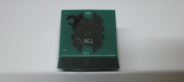
Figure 2 - Test Transformer #1
As you can see, this transformer has no external magnetic shielding, and it measures 24mm (long) x 20mm (wide) x 13mm (high, excluding pins). The values obtained are a combination of measured and calculated, especially for the primary inductance. The transformers are 1:1 - 600Ω in and 600Ω out. The electrical parameters I obtained are as follows ...
Parameter Value Measured With ... Primary Resistance 55Ω Ohmmeter Secondary Resistance 67Ω Ohmmeter Primary Inductance 1.83 H Inductance Meter (and obviously wrong) Primary Inductance 2.21 H Calculated Leakage Inductance 364 µH Inductance Meter
To calculate the primary inductance, I used a 100nF series capacitor (measured at 94nF), and resonance was at 349Hz. Input voltage was 89mV for a voltage across the transformer of 1V RMS at resonance. That represents a voltage peak of 21dB, an interesting observation, but not actually useful. Using the above formula, inductance was calculated to be ...
L = 1 / (( 2π × f )² × C )
L = 1 / (( 2π × 349 )² × 94n )
L = 2.21 H
The leakage inductance was obtained with an inductance meter, by measuring the primary inductance with the secondary shorted. This is the standard way that leakage inductance is measured, but it can still provide an inaccurate reading depending on the meter you use. With a load impedance of 600Ω, 364µH means that the output will be less than 1dB down at 100kHz. This is more than adequate for even hi-fi applications, but this transformer is let down by its low frequency performance.
I measured around 1.1% THD with 300mV input at 30Hz, driving the transformer from a 50Ω source. This isn't a great result, but was a little surprising since the transformer I'm using here was never intended to work much below 300Hz. Expecting a low frequency extension of a decade (roughly 3.2 octaves) is unrealistic, but it works fine provided the level is kept low.
When I tested this transformer, the response was commendably flat - even down to 20Hz. Response was down by less than 0.7dB, which isn't bad for such a lowly component. The Zobel network shown in Figure 2 maintained flat response.
If you need some bass boost, it's easily achieved by using a series capacitor. Using a 100µF cap gave a small but useful 1dB boost at 20Hz, and smaller values will provide boost at higher frequencies. I'm not entirely sure why anyone would want to introduce a deliberate low frequency boost, but it can easily happen by accident. If a user decided that adding the cap was necessary to remove any DC (which is entirely true), it's important to ensure that the cap is large enough so that you don't create a series resonant circuit that is within the audio band.
A series resonant circuit is rarely an advantage, and Figure 3 shows what happens if the cap is too small - in this case 22µF. Although the resonance can be tamed quite easily by adding series resistance, that's at the expense of output impedance. The demonstration circuit is shown below, along with the modified frequency response graph.
Figure 3 - Test Transformer #1 Circuit And 'Accidental' Response
By adding the capacitor in series with the transformer, a series resonant circuit is created that boosts the output at low frequencies. You can add series resistance to tame the large peak, but a far better solution is to use a much bigger capacitor. There can be no doubt that blocking DC from the transformer will cause far less distortion than any capacitor, assuming that you believe that caps are somehow 'evil'. In this instance, a 220µF cap will cause no bass boost of any consequence at any frequency, and this is the optimum value for this particular transformer. Provided you know (or have calculated) the primary inductance, the resonant frequency is determined by ...
fo = 1 / ( 2π × √ ( L × C )), so for the example given
fo = 1 / ( 2π × √ ( 2.2 × 220µ )
fo = 7.2 Hz
I also tested a couple of other transformers, and the bass response will be boosted by resonance in all cases. It's very important to ensure that any capacitor used in series with the transformer primary is large enough to prevent unwanted boost. If you use a cap that's too small (possibly because you didn't think about resonant circuits), then you'll get response that looks like that shown below.
Figure 4 - Output Boost Due To Capacitance
In the above, let's assume that a 10µF cap was used, perhaps because it seemed like a good idea at the time. However there is no series resistance, so the cap and the transformer's inductance will combine to create a resonant circuit (just as shown in Figure 3). If one fails to realise that a series resonant circuit is created there will be a very large output boost at the resonant frequency, and (this is the killer!) the circuit will appear to be close to a short circuit across the opamp's output! The opamp may not be able to supply enough current, and will distort horribly.
You can see that the amount of boost depends on the load impedance, so this transformer output will sound quite different depending on the input impedance of the load. A high impedance load (10k) causes a boost of over 10dB at 34Hz, and that will be audible with almost all programme material. Because a series resonant circuit has a very low impedance at resonance, the drive circuit may be overloaded, so you can get both a clipping drive amplifier and transformer core saturation! Two serious problems for the price of one.
Transformers must always be used with care, and it's essential to test the circuit with the selected transformer. Failure to do so can cause issues as described, and while it might be declared as having 'better bass' than a system that's been optimised, it will be neither accurate nor predictable.
Fortuitously, a 'real' 600Ω 1:1 line transformer arrived not long before I was about to publish this article, so I was able to run tests on a more representative sample. The full details are explained below. This is a far more substantial unit than #1, with the core alone measuring 35 x 30 x 13mm. The basics of the transformer are ...
Parameter Value Measured With ... Primary Resistance 34.8Ω Ohmmeter Secondary Resistance 35.5Ω Ohmmeter Primary Inductance 5.09 H Calculated Leakage Inductance 153 µH Inductance Meter
To calculate the primary inductance, I again used a 100nF series capacitor, and resonance was at 223Hz. Using the formula shown earlier I was able to calculate the inductance. An inductance meter gave me a very wrong answer (around 700mH on the 20H range, but over-range on the 2H setting). Inconsistencies like that demonstrate clearly that the measurement is wrong, and you have to resort to calculating the inductance.
A photo of the transformer is shown below for reference. I have no qualms about displaying the manufacturer (Harbuch Electronics in Hornsby, Australia) as they are one of the very few transformer manufacturers left in Australia and richly deserve some promotion. The transformer itself is intended for high quality audio use, and is somewhat cheaper than most of the major (and better known) overseas makers. Overall performance is excellent, and it can easily handle +10dBV at any frequency in the audio range. High frequency performance is extraordinarily good, extending to well beyond 100kHz with no evidence of ringing - even with zero load.
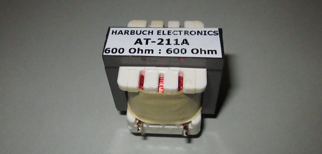
Figure 5 - Test Transformer #2
At 20Hz, distortion was only 0.15%, and with 100µF capacitor in circuit, there is a very slight boost at very low frequencies, with the output level rising to 3.13V (at 20Hz) from the 400Hz level of 3.09V (input was 3.16V RMS). This represents a change of 0.11dB which can safely be ignored.
I tested this transformer with the negative impedance circuits shown below, even though it's not really necessary. Distortion is commendably low at 20Hz, and further attempts at improvement end up making little difference. The added 'improvements' can easily make things worse by creating a potentially unstable condition with infrasonic signals.
Before describing negative impedance drivers, it's necessary to explain the concept. A physical resistor has normal, positive resistance. If a voltage is applied to one end and a load to the other, current will flow that's directly related to the voltage and resistance ... Ohm's law. As the load resistance is reduced, the load voltage is reduced too, because more current is drawn from the source and more voltage is 'lost' across the resistor. This is the principle behind a voltage divider.
A negative resistance (negative impedance is more accurate) cannot exist in nature, and must be built using active and passive parts (Note 1). If a load resistor is connected to the output of a negative impedance circuit, again, current will flow. However, if the load resistance is reduced, the output voltage increases. In fact (and very much in theory), if the 'real' resistance (impedance) is exactly the same value as the negative impedance, the two cancel and the result is zero ohms. The circuit will attempt to provide infinite current at an infinite voltage (real circuits will prevent this of course). This is not an easy concept to grasp, but hopefully the following will make sense regardless.
If the drive amplifier is configured to have negative impedance, and that exactly equals (but is opposite to) the winding resistance, the inherent limitations of the transformer are all but eliminated. However, as noted earlier, negative impedance circuits are inherently unstable, so it is necessary to ensure that the circuit used cannot oscillate or do anything else that you wouldn't like - regardless of what the load might do. The circuit is known as a negative impedance converter (NIC).
Using a NIC to drive the transformer means that the primary inductance doesn't cause low frequency rolloff, so at low levels the output from transformer #1 can be flat down to as low as 8Hz. At realistic levels (around 0.5V RMS) the minimum useable frequency is 20Hz.
This isn't a new idea by any means, and it is the subject of several patents [ 3 ] and has been described by some transformer manufacturers. No-one seems to have discussed any problems though, which is unfortunate. In particular, negative impedance is treated as if it were the most natural thing in the world, something it most definitely is not. Over the years, I have experimented with negative impedance amplifiers on many occasions, and while the idea always seems good, the unstable nature of these amplifiers (in particular with non-linear loads) is often their downfall. The situation may be a little different when driving small signal transformers, but there are still some issues that you have to deal with.
Figure 6 - Negative Impedance Driver #1
The circuit shown above is one way to achieve the required result, and it provides an output signal that cancels the winding resistance and the distortion generated as the core saturates. I was unable to simulate the effects of saturation realistically, so the circuits were built and the waveforms are shown below. Both circuits I tested work very well (but with caveats).
It is important to understand that when a negative impedance converter is loaded with a positive resistance that exactly equals its negative resistance, the gain is - theoretically - infinite! That means that the above circuit will have problems with DC offset. Capacitor coupling is not really an option unless you are prepared to use a very large capacitance (at least 2,200µF and preferably more).
The above circuit must be driven from a low impedance source, using at least a 12dB/octave (preferably 24dB/octave) high pass filter (not shown). The filter is needed to remove infrasonic frequencies. The negative output impedance is determined by the value used for R4. In this case, the transformer's winding resistance is 56Ω, so R4 would in theory also be 56Ω. To prevent the possibility of infinite gain, this was reduced to 51Ω. DC coupling is required, or a very large coupling capacitor is necessary (not less than 2,200µF). The series capacitor creates resonance, and the circuit will be unstable at the resonant frequency. Any transient will generate a possibly large infrasonic frequency disturbance at the input of the transformer. With no coupling cap, the DC Offset control is used to ensure that there is no DC across the transformer (DC gain is very high!).
The inclusion of an input filter is essential, as it reduces the input level at frequencies where the NIC will attempt infinite (or at least extremely high) gain. The only sensible way to tame the circuit is to ensure that the negative impedance is somewhat less than the worst case positive impedance. While you will sacrifice some of the benefit of the NIC by making its impedance less than the optimum, the circuit will be far less troublesome if R4 is made 51 or 47Ω instead of 56Ω. While the full benefit isn't achieved, there are fewer problems.
Figure 7 - Negative Impedance Driver #2
Figure 7 shows an alternative NIC circuit. This version has the advantage that it can never have infinite gain at DC, and doesn't need a very high value capacitor. However, it is still not without problems. The input capacitor (C1) must be chosen carefully to roll off the output at a sensible frequency, and C2 must be at least 10 times the value expected (based on the standard capacitive reactance formula). The -3dB frequency with 10k and 22µF is 0.7Hz. Depending on the opamp, this circuit might still require a DC offset control because the transformer itself is DC coupled, although measured offset was very low during tests. The transformer primary is wired in reverse, because the circuit is inverting.
In most respects this circuit is an improvement over that shown in Figure 6, and while the difference is largely academic it can handle 'real world' variations. This is the circuit that I would use in any real application, because it has unity gain at DC. C1 is absolutely essential, and the value is dependent on the transformer. C2 isn't quite so important, but it does need to be much bigger than you might think. With the other values as shown, there is no benefit to be gained by making it larger than 22µF as shown. C1 and C2 are shown as bipolar (non-polarised) electrolytics, but standard electros can generally be used with no ill effects. Using this driver with transformer #1, I was able to get 500mV at 20Hz with only about 0.8% distortion - very similar to what was seen with the Figure 6 circuit.
While this version needs two extra capacitors, a DC offset control is not necessary (it's mandatory with Driver #1). Performance is otherwise equivalent, although after testing both circuits, I recommend this one. A major benefit is that it can never have high gain at DC or very low infrasonic frequencies, which means the high pass filter isn't as critical. On the negative side, the transformer's primary is floating, with neither end of the winding connected to earth/ ground.
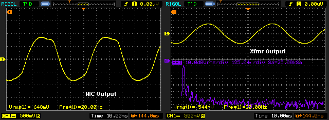
Figure 8 - Negative Impedance Driver Output & Transformer Output
The above is a direct capture from my oscilloscope, and used the circuit shown in Figure 6. The NIC output is shown on the left, and is quite obviously very distorted. The right-hand capture shows the output and an FFT showing the harmonics. Distortion at the transformer output is 3.8%, vs. 14% if the transformer is driven directly from the audio generator. The frequency is 20Hz, and the input level is 600mV. With 500mV input, distortion is around 0.8% at 20Hz.
The input waveform is distorted, and the distortion (almost) exactly compensates for the saturation effects in the transformer that would otherwise cause the output to be distorted. Low frequency response is theoretically flat to only a few Hertz, but in reality the opamp will clip should the transformer magnetising current become too high. This happened with my test transformer (#1) at about 13Hz with a signal level of 600mV RMS. At 30Hz, output distortion is reduced from 5% to only 0.25%, which is pretty good for a cheap and nasty little transformer.
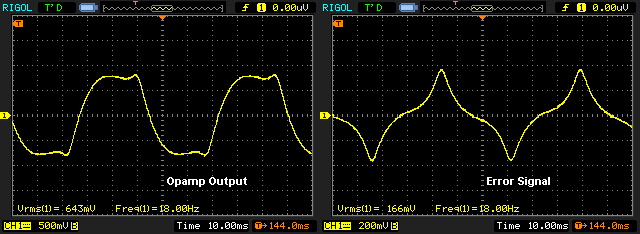
Figure 9 - Negative Impedance Driver Output & Error Signal
The above was captured using test transformer #1, and with the Figure 7 driver circuit. At a frequency of 18Hz (500mV), the transformer core is saturating, but is just below the limits where the drive circuit cannot compensate. The drive waveform is highly distorted (around 16% THD), and the error signal is developed across R4. Transformer output distortion is 1.6%, but it would also be 16% or more if the transformer were driven from a normal voltage source. While this all looks very promising, intermodulation distortion can be expected to be much higher than you would get from a better transformer.
With any NIC, should you be tempted to make the output impedance exactly the same as the winding resistance, you will get the effect of close to infinite gain. In all cases, I recommend that the negative output impedance should be about 10% less than the transformer's primary winding resistance. If the negative impedance is greater (more negative) than the winding resistance, the circuit may oscillate at some infrasonic frequency, and will be very unstable when subjected to transients (such as tone burst signals, which I tested).
I ran the same test with transformer #2, but with the output impedance reduced to -33Ω to suit the transformer's winding resistance. With an input voltage of 7V RMS at 20Hz and a 50Ω source (my generator), the transformer had 0.45% distortion. That was reduced to only 0.064% using negative impedance drive. So, while negative impedance certainly works exactly as expected, the level and minimum frequency must be tightly controlled or bad things will happen. This means a very good high pass filter, as well as 'de-tuning' the circuit to prevent excessive gain at very low frequencies where the inductance has little effect.
Another thing that you need to be aware of ... the drive circuit has to be able to provide the current required by the load, plus the non-linear current required by the transformer as it enters saturation. Many opamps will be unable to manage without creating considerable distortion themselves. Some small IC power amps can be used, but most are not unity gain stable so are eliminated. Output stage protection is a must, or the drive circuit may be destroyed by the first infrasonic 'event' it encounters.
In most cases, it will be far less risky to use a traditional low impedance drive circuit with a high-quality transformer than to attempt negative impedance. Performance can be very good, but the transformer will be expensive - expect to pay AU$50 - AU$100 or more for a transformer from a reputable supplier. Even then, performance may not be quite as good at low frequencies, but you are also far less likely to create ongoing problems. For test transformer #2 the distortion reduction was theoretically worthwhile, but reducing distortion from 0.45% to 0.064% at 20Hz (7V RMS or +17dBV) may not really worth the effort - especially since there is almost no energy at that frequency with most programme material. At sensible operating voltage at low frequencies, the distortion will be negligible.
While a decent audio transformer will have very little influence on the overall sound quality with normal programme material, this is definitely not the case if the core saturates. For this reason, no audio transformer should ever be allowed to have any drive voltage at a frequency where the core enters saturation. If this is allowed to happen, there will be severe intermodulation of all signals. While you might be quite sure that you'll never have any infrasonic energy in your programme material, it's usually present anyway. Whether you are using negative impedance drive or not, it's always wise to include a good high-pass filter. The frequency should normally be set so that the transformer core cannot saturate at any signal level within the capability of the equipment, and the rolloff should be a minimum of 12dB/octave (second order). Better protection is obtained with a higher order (24dB/octave is usually enough).
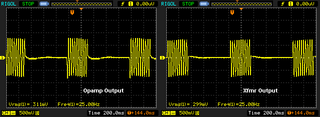
Figure 10 - Infrasonic Disturbance Created By Negative Impedance
For example, the above waveforms were captured using a 30Hz tone-burst signal. My oscillator certainly doesn't create any disturbance, so the low frequency effects you can see are the direct result of using a negative impedance drive circuit without an effective infrasonic filter. Given that the frequency is so low, you might imagine that it cannot get through the transformer, but you would be mistaken. C1 was 10µF rather than the suggested 2.2µF so the result is exaggerated, but it's still something you need to be aware of. The simple act of turning a signal on and off creates some infrasonic energy, and the same applies to music signals that start and stop or have an asymmetrical waveform.
Figure 11 - Simulated Infrasonic Disturbance With Negative Impedance
The above is a simulation (again using a 10µF cap for C1), and exactly the same issue is apparent. The waveform shown is at the output of the drive opamp. When C1 is reduced to 2.2µF the effect is reduced, but is not eliminated. This proves conclusively that the effect is both real and easily demonstrated by any method. So, the requirement for a infrasonic filter is very real indeed, and it also provides additional benefits.
Once a transformer core saturates, it's much like a clipping amplifier - parts of the input signal are removed, including other frequencies that are presented along with the one causing saturation. As demonstrated above, the frequency that causes saturation may not even be audible, and there are many potential sources of such low frequencies. Many will be transient and/or intermittent, and can cause problems that can be very hard to track down if you are unaware of the possibilities. Because the transformer has a finite inductance, the load on the drive amplifier increases rapidly when the core saturates, so the drive amp will either go into current limiting (clipping) or it may fail if it is not protected against short circuits.
It's obvious that DC is also capable of causing saturation, and even a hundred millivolts of DC will usually cause gross distortion at low frequencies. As the frequency is reduced, the amplitude needed to cause partial saturation is reduced as well. If a 5V signal at 40Hz causes (say) 10% distortion, then only 2.5V is needed at 20Hz or 1.25V at 10Hz to do the same. As noted earlier, it's a good idea to include a high pass filter in front of the amplifier that drives any audio transformer, with the cutoff frequency selected to prevent significant distortion at any level below drive amplifier clipping. For example, if a transformer shows 5% distortion with 4V input at 35Hz, then you might want to restrict the maximum input level to 4V and add a 12dB/octave filter tuned to no lower than 35Hz.
This arrangement will ensure that the transformer cannot be driven beyond the amplitude or frequency where significant saturation occurs. It is quite true (as discussed in Section 1) that the frequency-dependent nature of transformer distortion creates fewer problems than a similar amount of distortion from an electronic circuit. However, this assumes that the transformer is never driven into saturation. The distortion produced is extremely unpleasant and can be very audible indeed.
In general, impedance matching is neither recommended nor required. If you plan to send your balanced audio feed into a kilometre (or more) long line then yes, match the impedances, but otherwise don't even think about it. This is one of the oldest myths with audio equipment, and has created confusion for people for a very long time. Part of the problem is that many equipment manufacturers claim that the inputs are '600Ω'. In the majority of cases that's simply the nominal source impedance, not the input impedance.
If the source and load are both 600Ω (or any other equal impedance), there will be a loss of 6dB because a simple voltage divider is created. Matched impedances are necessary for very long lines (such as telephone systems) and for maximum power transfer as found with RF (radio frequency) installations. In the vast majority of audio installations, we are only concerned with transferring a signal voltage from one piece of equipment to another. The load impedance is almost always at least 10 times as great as the source impedance - a connection known as a 'bridging' load. Several such loads can be connected across the line without significant signal loss.
Even with microphone preamps, it's standard practice to make the input impedance of the preamp at least 2.2k, and often higher. Failure to observe this rule will result in a significant loss of signal level and an increase of noise because more gain is needed to account for the reduced signal. The same applies to 'line' outputs and inputs. While a transformer may be classified as being '600Ω', its actual output impedance is likely to be less than 200Ω, with much of that being the winding resistance of the transformer itself. Line inputs will normally be expected to have an impedance of 10k or more.
That means that even if the output impedance from the transformer is 600Ω (it will usually be a lot less), a 10k load only means a loss of 0.5dB. If the load were 600Ω, the loss is a full 6dB (half the voltage). With a more typical 200Ω output impedance, the signal loss is only 0.17dB (980mV from a 1V source voltage). This is a linear relationship, and it applies for any signal voltage below saturation, regardless of whether the signal is at -20 or +20dBV.
If you were to use the negative impedance option to drive the transformer, its output impedance is mainly the resistance of the secondary winding. This reduces the loss to almost nothing. For example, a 10k load on test transformer #1 causes a loss of 0.06dB when it's driven from a negative impedance source, because the primary resistance is cancelled by the -50Ω drive circuit shown in Figure 6.
Impedance matching does have one very minor advantage - the input voltage before saturation is increased slightly, or you can get down to a slightly lower frequency before saturation occurs. This is due to the resistance of the copper winding in the transformer's primary. The effect is small, and it is not recommended that you try to use this method to do anything useful. At 600mV/ 30Hz input (xfmr #1) I measured an output voltage of 557mV at 2.9% THD (almost completely 3rd harmonic). With a 560Ω load, the output fell 2dB (434mV) and the distortion was reduced to 2.0%. So, for a level reduction of 2dB, there was a 3.2dB improvement in distortion. While interesting, this isn't worth the effort. Simply reducing the input level to 500mV and operating the transformer with a high impedance on the secondary provided more voltage (463mV) and roughly the same distortion (2.2%).
A question that's sure to cross your mind is "can I use a mains transformer for audio?". The answer is "yes ... but", as it comes with many caveats. I tested a small (about 10VA) mains transformer, and with a 7V input it gave about 650mV output (nominally 230V to 22V output). Distortion performance was generally pretty awful, even at relatively high frequencies (400Hz and 1kHz). The distortion should have been negligible, but it wasn't, and it showed about 0.2% at both frequencies. A decent audio transformer would show less than a tenth of that (< 0.02%). Despite running the transformer with a fraction of its rated voltage, low frequency performance was poor, with easily visible distortion on my scope at less than 40Hz.
This is less than inspiring, and is largely due to the nature of the laminations used (copper wire doesn't cause distortion), and the expectation that there will always be a fairly significant amount of core saturation in use (as a mains transformer). Audio transformers use low-loss cores, but that's not the case for a mains transformer. So, while you can use a mains transformer for line-level audio, it's not recommended. Toroidal transformers are better in this respect, but that's an expensive way to get a signal transformer that will be far bigger than an equivalent 'audio transformer'.
Of course, transformers are used in valve (vacuum tube) amplifiers, occasionally for inter-stage (coupling) but almost always for the speaker output. Even when every care is taken with the design, the transformer will nearly always contribute some distortion, but it's usually not noticed because the valves create more distortion than the transformer. Negative feedback reduces both distortions, and is used in most (but not all) valve amps. The art of designing a good output transformer is becoming lost, which is a shame.
Just for interest's sake, I tested a 200VA toroidal transformer as well. It's quite apparent that it's not sensible to consider such a thing in an installation, but its performance was very good. Distortion at 30Hz with 1V output was 0.05%, and it's unlikely that many transformers would beat that. However, it's big and weighs almost two kilograms. A pair of those would work nicely for stereo, but somehow I expect that to be an unlikely solution.
Transformers are always interesting, despite their apparent simplicity. For anyone who hasn't already done so, I recommend that you read the Beginners' Guide to Transformers. There are three sections, mainly dealing with power transformers but also covering general principles. Most people don't really think deeply about transformers in any of their applications, but they are by far the most fascinating of all the passive components. There are also a lot of myths and misunderstandings, many of which show that the writers completely fail to understand the basic principles. It appears that part of my job is to dispel as many myths as I can. 
Using resonance to obtain a bit of low frequency boost is not something I've seen discussed, and this is a technique that can be used if necessary. You also won't find much info about the interaction of capacitors and transformers (unwanted resonance), and the required capacitance and optional series resistance can only be determined after careful measurement and some experimentation.
The circuit you use to drive the transformer must be capable of supplying enough current to feed the load and the transformer's magnetising current. This becomes more critical at low frequencies. If you need an output level of (say) +24dBV (just under 16V RMS), you will need either a small power amp IC or a step-up transformer because most opamps can't be operated at ±25V or more. Don't expect to get more than 10mA peak from most opamps (although some can provide up to 25mA peaks), and be prepared to engineer the drive circuit carefully or you won't get the performance you expect.
Using a negative impedance driver can improve performance dramatically, but it does come with serious caveats. It will be necessary to test the complete system very carefully to ensure that it can never become unstable with any frequency, amplitude or load. It's worthwhile doing a Web search on the topic if you are interested, as there is some information available. However, nothing I have seen mentions the unstable regions or gives any warning at all that bad things can happen once the drive circuit cannot handle the combination of the load and the transformer's saturation current. Most articles seem to assume that the negative impedance circuit will be directly connected to the transformer (no series capacitor), but don't offer any info on how to remove DC created by the NIC itself, nor do they warn you that a NIC can have very high gain at DC.
In general, I recommend that you select a transformer that is designed for your application, and use a low impedance (not negative impedance) source. While the use of a series capacitor is usually a good idea to prevent any DC in the windings, make sure that you test it thoroughly to ensure that resonance is well below the lowest frequency of interest. Ideally, the drive circuit will include a high pass filter to prevent any infrasonic frequencies from reaching the transformer.
As a final check, I did a listening test with transformer #1 and the Figure 7 negative impedance driver. The average voltage was around 1V RMS from an FM tuner, and the error signal (across R4) showed a surprising amount of activity with most of the music that was playing at the time. While I thought I could hear a difference between 'traditional' voltage drive and the NIC, I couldn't be certain. If there was a difference it was rather subtle, but the sound did seem a little cleaner with the NIC, especially with bass-heavy material.
However, it's far easier to reduce the level a little to reduce distortion to be within acceptable limits. That is a simpler method, and doesn't require messing around with negative impedance and the subtle problems it can create. Remember that it's always a good idea to include a capacitor in series with the primary, but make sure it's large enough so it doesn't create a series resonant circuit at any frequency above ~10Hz or so, and that there is no bass boost as a result. This needs to be measured so you can be sure. I consider the inclusion of a high-pass filter before the transformer drive circuit to be mandatory, whether a NIC is used or not.
The rest is up to you to experiment further.
1. Audio Transformers - Bill Whitlock (Jensen Transformers)
2. A262A2E Audio Transformer - Walters Group Holdings Ltd.
3. Low-distortion transformer-coupled circuit - US Patent US4614914A
4. Audio Transformer Design Manual - Robert G Wolpert
Main Index
Articles Index