

|
| Elliott Sound Products | Worldwide Ban Looms for External Transformers |
 Main Index
 Articles Index
It has now been some time since this was first published, and 99% of the information below is as valid today was when it was written. The only real change is that the ban is well and truly in place, so conventional iron-core transformer + rectifier external supplies are no more. All currently available DC supplies are switchmode, and without exception suffer from the ills I wrote about in 2007. Having said that, they have also provided a very cheap way to include a small DC supply into a product - especially where a somewhat noisy supply will not cause any problems.
The regulators were finally convinced that AC/AC external supplies must use a iron-core transformer, and the requirements were removed for these to have extremely small no-load power consumption. It did take some doing though, proving that the 'consultants' selected by the government were chosen because they would reinforce the 'official' position without dissent. Any knowledge of realities was never a requirement, so most of their input was either flawed or worthless.
As of the time of this update, no additional requirements for electrical safety have been introduced or even suggested, and having used quite a number of small external SMPS (switchmode power supplies) as part of other designs, I see that they are no better now than they were 3 years ago. The opportunity for the insulation barrier to be breached (by a variety of exciting means) is present in all I've seen. I do accept that the risk is low, but it is not negligible, as was the case with conventional transformers.
Everything else described below remains unchanged - the only thing that is different is that the ban is in place, and with the possible exception of some (very) old stock, the supplies available now are MEPS compliant. AC/AC supplies still use iron cored transformers (as they must).
I freely admit that the sky hasn't fallen, and the majority of people haven't noticed the difference. I have had a SMPS fail due to ROHS and lead-free solder (which applies to almost all modern electronics). I was able to repair it the first time, but it failed again and did itself an injury so had to be replaced. This is a problem that will only increase - the combination of lead-free solder and the much greater complexity of an SMPS compared to a conventional supply means more failures and more dead supplies being discarded. It is likely that the additional energy used to make (and ship) a new supply will negate the savings as calculated by the Australian Greenhouse Office, and I suspect that the real savings will be a small fraction of those claimed.
Update, May 2014 
At the time of the latest update to this page, the sky is still in place, but the problems are nowhere near solved. More dodgy switchmode power supplies are around then ever before. Meanwhile, Australians are paying an average of around 25¢/kWh (yes, you read that right!). There are a few minor changes below to reflect the cost of running various appliances, and some other small changes. The bulk of the article is unchanged, and the issues I addressed have not been fixed.
Let me start by pointing out that I am not opposed to energy savings - even small ones can be beneficial. I am opposed to anything that reduces safety standards, places users' equipment at risk (by capacitive discharge damage for example), or makes products virtually unusable. This can occur if the imposed technology introduces so much noise into the system that users can no longer use equipment that was perfectly alright when used with an old technology 'inefficient' power supply.
I am also opposed to laws or regulations (that affect everyone) being created, where there is no opportunity for the general public to have their say. Regulations are made by bureaucrats, and while they presumably have our best interests at heart, they cannot (and do not) generally understand the likelihood of 'unintended consequences' - things that really annoy, cause inconvenience or damage equipment - because no-one even thought of a particular application where the replacement technology is completely inappropriate.
In theory, a Regulatory Impact Statement (RIS) should cover the impact on new and existing equipment, cover all disadvantages as well as advantages, and not merely proclaim the energy and CO2 savings and the likely cost of the new product. The document referenced below has made no mention of the impact of a replacement switchmode supply on equipment designed for use with a conventional (transformer based) power supply.
On the Australian Government's Energy Rating library page, one used to be able to find a very scary document indeed. The document was a Regulatory Impact Statement (RIS - Minimum Energy Performance Standards and Alternative Strategies for External Power Supplies) and as originally published had the potential to create huge problems in the market place, and should be seriously reconsidered before any action is taken (the links have been removed as the document has either vanished or has been moved). It is notable that a document search failed to find any occurrence of the following words ...
... and indeed, SMPS failure modes (and their possible consequences), the potential for equipment damage or compatibility with existing equipment are not mentioned. Safety is mentioned, but there isn't a single reference to any possible safety issues. It is simply assumed that safety tests will ensure that every unit that passes the tests will be completely safe. I'm not so certain - there are too many things to go wrong.
The RIS covers external power supplies - those that plug directly into a power point (wall outlet) are also known as plug-packs, wall-warts or wall transformers. Others have a mains cable and an output cable, the most common example being the supplies used with notebook computers. Many existing supplies are already switchmode, and some of those may even pass the new requirements. Only two that I tested pass, most don't even come close, but their power dissipation still isn't unreasonable.
A mandatory energy rating requirement effectively bans all presently available transformer based external supplies because their magnetising current is higher than allowable. In order to pass, the no-load dissipation must be less than 0.5W for supplies rated at less than 10W, or 0.75W for supplies rated at between 10 and 250W. Most small transformers draw a magnetising current of around 20-30mA, and the range of power consumption I measured was between 1.1W up to 1.8W - this was verified with a fairly wide cross-section of supplies at my disposal. The dissipated power is directly related to the winding resistance, and also includes iron loss - that amount of power needed to reverse the flux in the core on each half cycle of the AC waveform). Very small transformers usually show minimal change in mains current between no-load and full-load, although the power does vary because of a slightly improved power factor at full load.
Note that certain battery chargers are exempt, in particular those that house the batteries or battery pack whilst charging. One can assume that any external supply that has an output lead that allows connection to anything other than a battery is included in the RIS.
The tests described herein were performed using a variety of methods. The most important is power consumption, so that the true power consumption of the various supplies could be measured.
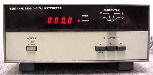
Power Meter Used for Testing
The YEW (Yokahama Electric Works) 2509 power meter was used to measure VA and actual power. These are never the same with inductive or non-linear loads, because of power factor. The apparent power (Volt-Amps or VA) is simply the RMS voltage and current multiplied together, but actual power (Watts) must be computed so that phase angle (for sinewave loads) or pulse currents are properly applied to the formula. You can't measure 'real' power without a power meter.
The VA was double checked using the RMS capability of my digital oscilloscope, together with an in-line current monitor. The output of the current monitor was also used to capture the current waveforms shown in the test section below. With all such measurements, there will always be some error, but I have taken pains to calibrate everything as well as possible, so errors will generally be less than 5%. Some of the error is a result of the distorted waveform - something that is very difficult to circumvent, because it can be extremely difficult to make very accurate measurements on badly distorted waveforms.
Most of the measurements will be well within acceptable limits, although power readings below 1W are subject to the usual ±1 digit with any digital instrument. I have yet to construct a current amplifier to allow the wattmeter to have a x10 range, which will increase accuracy for very low power levels. This will be done as soon as I have time to do so.
The processes in place actually seem to have very little to do with saving energy, but are political. The cost of operating a small power supply for a full year is extremely low - so low that it is only sensible to show it as a yearly value (it's less than 1 cent per day). As explained in greater detail below, this is utterly insignificant compared to other allowable losses and normal household activities.
Of far greater concern is that these regulations (as originally written) would have effectively banned external AC-AC power supplies. These are used extensively for alarm systems, ADSL modems and other products that use the AC input to generate dual-rail supplies internally, but they are also very useful for hobbyists who do not have the skills needed to wire a mains operated power supply. There is currently no alternative available with switchmode supplies - it could be done, but the cost and complexity are prohibitive.
With a great many typical loads (such as charging a cordless phone), the mains current doesn't change very much. several (transformer based) external supplies that I tested draw around 20mA at idle, and 24mA when loaded (off-load power dissipation is about 1.4W). At least with small external supplies, one knows what to expect. In contrast, the 'phantom' power of many appliances that draw standby power is unknown unless you measure it. The tested units results are tabulated later in this article.
One of the great advantages of a transformer based supply is that even though it may only be rated for (say) 100mA, you normally require 50mA, but really need 500mA for a very brief period, it will do so cheerfully. It can do this without failure for years, as long as its average power remains within ratings in the long term (between 1 and 5 minutes, depending on the size of the transformer). A SMPS can't do that - its maximum current is the limit, even for a few milliseconds. If you need a peak current of 500mA you have to use a 500mA supply. Its efficiency at low (average) power will be very poor, probably as bad or worse than a transformer.
It's impossible to say who is affected elsewhere in the world, but in Australia, the effects will be widespread. These new regulations do not require a vote in parliament, as (somewhat perversely) they fall under the Electrical Safety Acts of the various states (see links in the reference section). Because of the very nature of the regulations, they can be very difficult to interpret accurately, making the likelihood of anyone actually reading through the reams of information (literally) highly unlikely.
The definition of 'sell' for any product falling under the regulations now or in the future, includes ...
	(a)	barter or exchange; and
	(b)	let on hire; and
	(c)	offer, expose or advertise for sale, barter, exchange or letting on hire.
In other words, anyone with existing hire stock may be expected to discard any non-conforming external power supplies and replace them with new supplies (which for the most part didn't even exist at the time). This includes tool hire companies who offer battery drills with external supplies to charge the battery packs, computer hire companies for notebook computers and the like. In some cases, it also includes second hand goods, so it will be illegal (with some very substantial fines mentioned - see the references below) to even sell a second hand item with a non-compliant external supply.
Already, the simple act of discarding 'non-conforming' equipment and replacing it will completely wipe out any savings - the energy used to make the replacement supplies (and the CO2 liberated) will exceed the savings from using supplies that are rarely used with no load anyway. Even this assumes that replacements will be suitable or usable!
In some cases, it may be easier and cheaper for hire companies to scrap the tool along with its supply - even more wasted resources and energy. Many battery tools use fairly specific connectors, and although they are battery chargers, the suggested rules indicate that they may not be classified as such. Rather than become embroiled in a stupid legal battle with bureaucracy, not many people will risk the fines for non-compliance.
This has the potential to turn into an absolute nightmare!
The following letter was sent to the Australian Greenhouse Office. This does not simply relate to Australia - some of the provisions are already mandatory in some states of the US, and the EU and China are also parties to the discussions.
There are many factors that the author [of the RIS] has either missed completely, or glossed over - much of which appears to have originated overseas. While it cannot be denied that many existing external power supplies, plug-packs, wall transformers and other small external supplies are not particularly efficient, it has to be understood that the actual power used by most is quite low when not in use. Since the document appears to be primarily concerned with no-load performance, this is so minor in the greater scheme of energy savings that it is a fruitless exercise to waste time and money pursuing such an endeavour. Several things that the document has missed or glossed over are of great importance overall. These include ...
It is assumed that having a regulated output is beneficial, and saves equipment manufacturers from having to include a regulator in the equipment. This is only partially true. The output from most small SMPS is noisy, having significant high frequency noise superimposed on the DC output. Many small SMPS react very badly to additional filtering capacitance used at the output, because of regulation feedback loops that are marginally stable. Noise reduction is therefore non-trivial, and could conceivably actually increase the cost of the powered item. Where the product requires a noise-free supply, manufacturers will still have to include either complex filtering or a linear regulator to remove high frequency noise, and/or provide a lower voltage (typically 5V) for digital electronics in the device. Where a product draws a widely varying current, many small SMPS units are incapable of maintaining good regulation over the full range. It is common that with very light loading, the voltage is very unstable, causing a low frequency modulation of DC voltage - this is not usually any multiple or sub-multiple of the mains frequency, but is determined by the time constant(s) within the stabilisation feedback loop. None of these problems occur with existing linear supplies. Although the output voltage varies with load, the variations are predictable and easily accommodated by most circuitry. As noted above, a 'bulk' filter can be used to reduce waveform distortion, but such an item will be expensive, will have to be installed by a licensed electrician, and will consume some power in its own right. This power is wasted, and could easily exceed the savings made by replacing linear supplies with SMPS. It is also difficult to ensure that such a filter has no adverse effects on the distribution system, regardless of the number or type of non-linear loads for which it needs to provide compensation. As should be obvious, none of these issues have been properly tested, verified or factored into the draft proposal, either within Australia, the USA, China, Europe or anywhere else. The ramifications of a ban imposed upon traditional linear power supplies simply because they do not meet an arbitrary minimum efficiency figure are widespread and somewhat unpredictable, because of the huge diversity of applications. I urge the appropriate persons and agencies to review the proposed scheme as a matter of urgency. While there are claims of huge savings, these are almost all illusory. The vast majority of external power supplies are connected to equipment that is intended to be powered continuously. Where this is not the case (modem and printer power supplies being two examples), a far greater saving is available by simply using a switching system that is activated by the host computer. If the host machine is on, the devices are likely to be needed, but when turned off, the attached supplies can be completely disconnected. It is very important that any regulation considers not the standby power consumption, but the standby VA - especially for non-linear power supplies where there is no effective way to remove the harmonics generated. While a small switchmode supply may dissipate as little as 0.5W at idle, the same device still consumes current in order to function. The nature of the current can easily give a power factor of less than 0.4, so 0.5W becomes 2VA (e.g. 8.7mA at 230V). It is unrealistic to expect any SMPS to draw less current than perhaps 10-20mA at idle, regardless of its full load current. This equates to between 2.4-4.8VA, but measured power can (and will usually be) be significantly lower. To treat the VA rating as unimportant or 'invisible' is to defeat the entire purpose of any act or standard intended to reduce the waste of electrical energy. To make matters worse, the non-linear current waveform does not return the reactive portion of its current to the supply (as will an inductive or capacitive load) because the current waveform is non-reactive. In summary, I suggest that the current recommendations be revised to reflect reality rather than illusion, as they are impractical and deny the reality of the effects of millions of small harmonic current generators attached to the electrical distribution grid. Let us not forget the myriad of small appliances that use AC-AC external supplies, that simply cannot be replaced with switchmode supplies using available technology. Even if this were to change overnight, it is doubtful that a switchmode replacement could equal the performance of an iron cored transformer. Regardless of any objections to the contrary, these supplies are very common, and their contribution to energy loss is negligible compared to the standby power consumed by just one typical television receiver. |
The above covers most of the important points, but I did refrain from stating the obvious - that those who are pushing this latest affront are deluded if they think that what they plan is capable of making any difference whatsoever. There are countless items in the average home (not including businesses - the biggest power wasters of all) that draw as much current on idle as all the external power supplies put together. I have no objection whatsoever to any reduction in the standby power consumed by appliances that are not being used - ideally, the standby current should be zero. If something isn't being used, then why does it need to consume any current at all? We certainly don't need a clock in every piece of equipment we own, and the continuous display of the time (usually wrong) is pointless and annoying. However, many of these appliances have a need to know the time (for timed operation for example), so the time does need to be maintained. It does not need to be displayed!
However, all things need to be maintained in context - something that is not being done in the arguments. It is easy to make it appear that something useful is being done by using statistics and emotive methods, and these are at the forefront of the vast majority of the discussions at present.
Speaking of keeping things in context, I had a problem with the next diagram. It doesn't really fit in anywhere, but it is important.
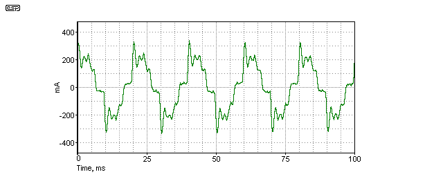
Figure 1 - Harmonic Current Caused By Capacitor
The link to the Integral Energy report about the danger of harmonic currents will mean something to a very small number of people. To make it clear to all, I recorded the current waveform through a 2µF capacitor, connected directly across the mains. Normally, the voltage waveform looks a bit distorted, but otherwise it has no spikes or peaks or other 'nasties' on it. Compare the voltage waveform shown below to the current waveform above. This is a perfect example of the issue discussed in the paper, and shows just how easily the amplitude of harmonics can be increased by capacitance. The waveform shown is current, but that current will cause a similar shaped voltage to appear across the length of any cable, and higher capacitance will cause more problems because more current flows. The harmonic structure is quite visible - although analysis is more difficult. The ripples at the peak of the waveform are the main problem. Somewhat surprisingly, the kinks at the zero crossing followed by vertical transitions are simply the result of the slight voltage waveform clipping, phase shifted by the capacitor. The peaks and 'squiggles' that you see at the crest of the wave is harmonic 'magnification' - exactly as described in the Integral Energy paper.
Current through the 2µF cap should have been ~144mA at 230V input, but was measured at 166mA. That's a 13% increase of current, all caused by additional harmonics introduced into the mains waveform by non-linear loads elsewhere on the supply grid. The exact cause of the extra harmonics is not known for certain, but the referenced paper does give some clues.
On the basis of this simple test, we can say with certainty that the problem is very real, and that the situation is far more complex than we may have imagined. Likewise, we can be certain that as we increase the number of non-linear loads, we will increase the severity of the problems faced by power companies. As is to be expected, if they have to do something to fix the problem, we will pay for it.
I have run tests on as many of the small linear supplies that I can get my hands on, and the results are quite predictable. None achieve the expected outcome for no-load power consumption, but once placed in context it is easy to show how little difference these moves make in real terms.
Before continuing, let's compare the schematics of a linear and a switchmode supply. Note that the SMPS circuit is simplified fairly dramatically, because they are rather complex devices despite external appearances.

Figure 2 - Linear DC External Power Supply Circuit
There's not much to it - just a transformer with a built-in thermal fuse, a bridge rectifier and a filter cap. Because there is so little technology involved, there is also very little that can go wrong. A sustained short circuit at the output will simply cause the thermal fuse to open, which will happen at around 130°C. Although this means the supply is no longer usable, it happens very rarely. Most of us have transformer based supplies that are many, many years old, and still work fine.
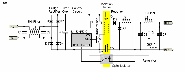
Figure 3 - Simplified Switchmode DC External Power Supply Circuit
As you can see, even in simplified form, the SMPS is much more complex. More parts means more things that can (and will) go wrong, and the lack of a central primary potential heat source makes full thermal protection more difficult. The isolation barrier is bridged by either one or a pair of Y1 class capacitors - these are designed so they can never fail short-circuit, but I have my doubts that every single Y1 cap (C4 & C5 in the above) ever produced by anyone, anywhere (including fakes!) will provide adequate protection for 20+ years. Further problems caused by these caps are discussed in more detail below. Occasionally, Y2 caps are used. These are a lower specification, but it apparently acceptable to use two Y2 caps in series rather than a single Y1 cap.
Electrolyte leakage from a failed filter capacitor could easily bridge the isolation barrier, making the output of the supply potentially lethal. While the chance of this (or other possible failure mechanisms) may be small, it's much more likely with an SMPS than any linear supply. The latter have been used for a very long time, with no fatalities recorded that I could find. It is worth noting that the RIS does not apply to medical applications, simply because the leakage current is far too high because of the Y1 capacitors that are used in almost all cases.
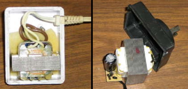
Figures 4 & 5 - Linear Power Supplies
The above photos show an AC supply (on the left ... which was strangely marked as being 3V DC), and a normal DC plug-pack, in this case rated for 12V at 1A output. As you can see, there's almost nothing inside. The transformers are wound on a split bobbin, so primary and secondary are side-by-side. This is done for safety, and also reduces the capacitance between the AC mains and the output. With the internal thermal fuse, these transformers are considered to be safe when used according to the datasheet.
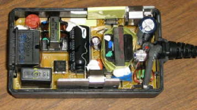
Figure 6A - Switchmode Power Supply
No comparison in terms of complexity, and you can't see the underside of the board which is covered with surface mount components. This particular supply is for a digital camera, and is rated for 7V at 2.1A. This supply will not pass the new regulations either - it draws far too much power at idle (1.1W). In common with nearly all SMPS, the DC output is rather noisy, with 7mV RMS noise, but having noise spikes reaching as much as 50mV. These require additional filtering to clean up the noise. A typical linear regulator will have less than 1mV output noise, and with no high frequency noise spikes at all. Regulation of the SMPS output voltage is only fair - nowhere near as good as you will obtain with a high quality linear regulator.
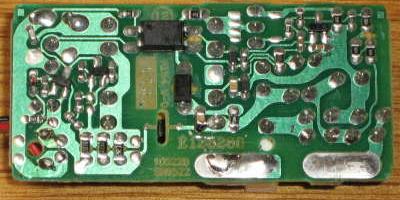
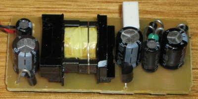
Figure 6B - Mobile Phone SMPS - Bottom of Board Figure 6C - Mobile Phone SMPS - Top of Board
The mobile (cell) phone charger shown above exceeds all requirements. Although you can't see all the parts on the copper side of the board very well, there are quite a few - all surface mount. In terms of complexity, it's less complex than the camera supply, but also has to supply a lot less power.
Another small SMPS I tested draws about 2.5mA at idle - that's not a lot of current, and represents 0.6VA. No-load power is about 0.4W, but this is difficult to measure accurately when the meter only has a resolution of 0.1W. The supply rating is 12V at 400mA, or 4.8W. At full output power, consumption rises to 9.4W, representing 51% efficiency. While many will be somewhat better than this, many will be the same or worse. A roughly equivalent transformer supply draws about the same at full load - the difference in real terms is tiny. And yes, like many such supplies, the output of the SMPS floats at 120V (see below for more on this subject).
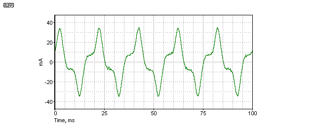
Figure 7 - Linear Supply Current Waveform
The above is the actual captured current waveform from a cordless phone AC supply. The waveform is rather distorted, but has a very low harmonic content and is generally considered benign. The current measured at 17.5mA with no load, but the waveform does not change dramatically when the transformer is loaded normally (for example when plugged into the charger base).
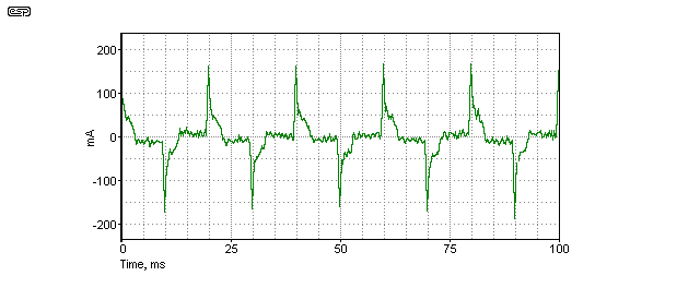
Figure 8 - Switchmode Supply Current Waveform
In contrast, the current waveform from a SMPS is very spiky (this is also a direct capture of the measured current), and has harmonics that extend to quite high frequencies. Although this was not measured, any waveform with sharp transitions must have considerable high frequency content. The waveform shown is with the supply loaded to about half power. Unlike the transformer unit, the waveform does change considerably as load is increased - the current spike gets larger. Mains current was measured at 43mA RMS, but as you can see the peak current is about 160mA.
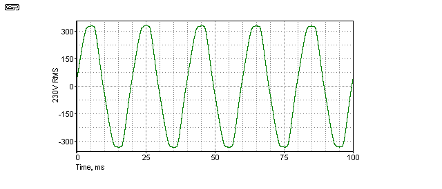
The voltage waveform shown is measured directly off the mains using a divider circuit. You can see how the wave shape is modified with 'flat-topping' caused by the myriad of switching power supplies connected to the grid - all drawing current at the peak of the mains voltage. Distortion was measured at 4.5%.
As mentioned above, I measured a number of supplies - both switchmode and linear, the results are shown below.
| Rating | No Load | Full Load | ||||||
|---|---|---|---|---|---|---|---|---|
| Type | Voltage | AC Current | Power In | Test Current | AC Current | Power In | Efficiency | PF |
| SMPS | 5V DC | 3mA | 0.4W | 1A | 72mA | 9.0W | 55% | 0.52 |
| SMPS | 5.7V DC | 1.3mA | < 0.2W | 710mA | 46mA | 6.5W | 70% | 0.58 |
| SMPS | 7V DC | 14mA | 1.1W | 1.8A | 130mA | 16.9W | 75% | 0.54 |
| SMPS | 19V DC | 14mA | 2.2W | 2.35A | 130mA | 16.9W | 75% | 0.54 |
| Linear | 6V DC | 26mA | 1.9W | 300mA | 23mA | 2.7W | 66% | 0.49 |
| Linear | 9V DC | 19mA | 1.4W | 200mA | 22mA | 4.0W | 45% | 0.76 |
| Linear | 9V AC | 20mA | 1.4W | 300mA | 24mA | 4.3W | 62% | 0.75 |
| Linear | 12V DC | 28mA | 1.6W | 400mA | 48mA | 10.0W | 48% | 0.87 |
| Linear | 12V DC | 21mA | 1.4W | 400mA | 53mA | 10.6W | 45% | 0.83 |
Note: All ratings and measurements are for 230V 50Hz mains supply. Test current is as close as practicable to rated output current
A motley assortment, but the linear supplies are representative of those likely to be found in most homes. They cover a range of ages, from only a couple of months to quite a few years. As you can see, the power factor of most of the linear supplies is acceptable, but overall efficiency is not good. The miniature 5V SMPS also has rather poor efficiency - there are losses that simply exist regardless of how much we'd prefer they didn't.
Most of the linear supplies have a reasonable power factor at full load, although there is one anomaly, having a PF of only 0.49. Even this is not as potentially harmful to the power grid as an SMPS, because the waveform distortion contains predominantly low-order harmonics.
For most of these supplies, efficiency is a minor issue. They are rarely used to maximum capacity, and may only ever supply less than half their rated current in normal use. Using supplies at less than full load has a greater effect on the efficiency of switchmode supplies, and may become worse still because of their inability to handle transient loads above the maximum current rating. As a result, a larger than expected supply may need to be used to be able to supply any high transient current drawn by equipment.
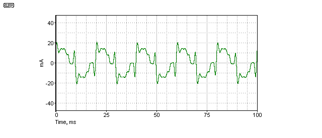
Figure 10 - Notebook PC Supply Current Waveform, No Load
An excellent example is the supply for a notebook (laptop) PC. At idle, the current waveform is as shown above - it is very spiky, and shows that there are lots of harmonics generated. While the supply is idle, it's actually not too bad, but only because the current level is quite low. When called upon to do some work the situation is very different.
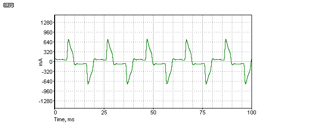
Figure 11 - Notebook PC Supply Current Waveform, 2.3A Load
The waveform now has a major (and very sharp) current spike, which occurs at the very peak of the voltage waveform. The harmonic content of this waveform is pretty nasty - it's so bad that the distortion reading looks impossible. My distortion meter insists that the THD is about 80%, and the simulator can be configured to include a distortion meter that gives roughly the same result (using the same technique as a real distortion meter).
It is important to understand the processes that all interact here. Many people have found that sound recorded by a notebook PC is unacceptable if the supply is connected, so run on batteries while recording. It's often not the PC supply causing the problem directly - the harmonics get into the external equipment and ruin the signal to noise ratio before it even gets to the PC.
Unfortunately, the logic used in the arguments presented for a ban of 'inefficient' power supplies (or lights) is not scientific but emotional. Energy saving data will not usually be given for a single supply, but the total number claimed (or dreamed up) in use will be used to inflate the outcome. If there are a million 1W supplies, and each can be made 50% efficient instead of (say) 25%, we 'save' 250,000W - assuming they are all in use. Now we can assume they are all powered 24/7, so we can save 2.19GWh a year. Because that sounds like a big number and the CO2 number will also be very impressive, people will "ohhh" and "ahhh" appropriately.
No-one seems to be able to agree about the amount of CO2 produced per kWh, but around 900g/kWh seems reasonable *. That makes 1,970 tonnes of CO2 for 2.19GWh. This is indeed an impressive number ... if viewed in isolation. If we break it down, each unit saves 0.25W, or 6Wh / day and a few milligrams of CO2. This is not at all impressive so naturally you'll never see it described that way.
* There's not a lot of agreement about the amount of CO2, but the figure used seems reasonable.
Note: The referenced RIS document expands on my little example by assuming that Australia has 34,000,000 (34 million, 1.6 supplies for every person in the country), and that every single one of them is operating continuously at well over 3W. This is obviously nonsense!
** I know that human breathing is irrelevant and 'unscientific', but it's interesting and helps put everything into perspective.
Lets compare the 'saving' above to the energy used by one of the simplest household activities imaginable (and I could rework this 'RIS style' so that all 21 million Australians do the same thing - even if less than 5 years old). A million people open their fridge door a few times a day, thus turning on one or two 25W lights for a total of (say) 5 minutes each day. This also involves losing some of the cool air in the process, so the fridge compressor has to run to restore the temperature. We will completely ignore the energy used by doing this!
Having retrieved the milk, we'll assume that only once per day our 1,000,000 people will want to boil water to make tea or coffee. The kettle will be typically 1kW, and takes just over 3 minutes to boil 500ml of water. That's 51.6Wh / day per person, or almost 19GWh / year (as well as 17,100 tonnes of CO2) - just from 1 million people making a single cup of tea/ coffee per day.
That's over 8 times as much energy as would be saved by swapping over to 1 million more efficient power supplies. As we can see, banning tea and coffee will save far more energy than most other measures suggested put together! This is especially true of people who have more than one cup a day - shame on them!
We must also consider the cost to the environment and the users when supplies fail and have to be replaced. There's the obvious waste of resources in the failed (and rarely recycled) supply, plus the cost of making, shipping, storing and retailing for the new supply. I know it's not fashionable to still be using last week's phone or tablet, so most people will never keep these supplies for long enough for them to stop working. Many (perhaps even the majority) will not be recycled, and will go to land-fill. Some will be stuck in a drawer for a while first, but essentially their fates are sealed.
The so-called '1W initiative' (where all appliance standby power is reduced to 1W or less) is a bit like patching a small hole in a roof, but failing to see that half of it is missing altogether. Not that I object to measures that will save power, but the standby power of plug-pack and similar supplies is a tiny fraction of the total power that's lost overall, and to demand the use of switchmode supplies and fail to demand PFC (power factor correction) is foolish in the extreme. That safety and longevity may be compromised as well is not at all satisfactory.
While many devices may be able to pass the basic requirements, some disable PFC when idle in order to do so (see Electronic Design - this is a suggested method to reduce power). Not just power, but VA (also called 'apparent power') needs to be reduced at the same time, or the whole process is marginal and results only in more harmonic noise on the supply grid. At present, the measured THD (total harmonic distortion) of the 50Hz mains measured at my workbench is 4.5%.
It's not that there's an inherent issue with reducing wasted power, but measures have to be taken in context with overall usage and how much can really be saved by reducing the standby consumption of devices that are really already quite low anyway. There are many other things than can be done that will make far more difference, such as minimising the power used for street lighting and carparks. There's a railway commuter carpark opposite my house, and it uses what look like mercury vapour lights that are on all night, even after trains have stopped running. If the lights were converted to LED and used motion sensors, the lights could be dimmed when there's no-one using the carpark, and only those lights where movement was detected would switch back to full brightness. The potential saving would be far greater than my total consumption of electricity for the day.
It is worth noting that most of the measures being looked at target individual households, yet household energy usage is small compared to that of commerce and industry. A single small office block may use several hundred fluorescent lamps (not to mention PCs, boiling water urns, etc., etc.), which are often left on all night. At 36W per lamp, and (say) 250 lamps left on all night for 'security', that amounts to 9,000W that is wasted for at least 8 hours a day. Over 26,000kWh per year is squandered, almost 24 tonnes of CO2 is liberated, and that's for one small office block. (See, I can invent a bunch of numbers too  ).
).
To put this into full perspective, consider that the same regulatory bodies in Australia have recently reduced the allowable power dissipated by small (63 litre) hot water systems to 1.33kWh / day. That means an average loss of 55W, all day, every day, with no hot water being used at all. The losses are all due to heat loss through pipes and insulation. See MEPS Requirements for Electric Storage Water Heaters for full details. Compare that to the minuscule power dissipated by a few external power supplies. On the one hand they quibble about 2 or 3 Watts (a few Wh/day), and on the other consider a heat loss of 1.33kWh/day to be acceptable. The fact is that it probably is 'acceptable' if one just looks at the economics - it will be expensive to provide additional insulation and other measures to reduce heat loss further, but the potential for real savings is immeasurably greater. The power lost by one or two small transformer supplies operating continuously is less than that needed to re-heat the water in the heater after washing one's hands just once per day. With 1.33kW/day, you could run over fifty plug-pack wall supplies continuously and still be well below that figure.
None of this has anything to do with reality - it is all politics. Politicians (and bureaucrats) need to be seen to be doing 'things' as expected by their constituents (or the political party in power at the time). By making lots of noise about something utterly insignificant and using statistical 'evidence' to prove how much difference it will make, the public is easily hoodwinked into believing that things are changing and/or that the government is serious. The overall effect of applying minimum performance criteria to something as trivial as a small external power supply is almost certainly between zero and negative in the long term.
Small devices such as mobile (cell) phone chargers will normally be switched on when the phone needs charging - why would it be left powered if it's not doing anything? It probably doesn't help much that in the US (among other places), power outlets normally do not have a switch. All standard wall power outlets sold in Australia are fitted with a switch, so it's easy to turn things off without even removing them from the outlet.
Some Australian power points aka GPOs - general purpose outlets, aka wall outlets) are fitted with a neon indicator. These are fairly uncommon now, but were popular for a while. Each neon draws around 50mW (0.05W) for no useful work. Perhaps the regulators should introduce the death penalty for those still using such abominations!
To appreciate just how silly this ruling really is, we need to look at some real examples. There is no point quoting hypothetical figures and multiplying by the assumed number of external power supplies that may exist. To see the reality we need to take measurements such as those shown above, and compare the power usage with normal household activities.
If an appliance draws 100W, that is simply 100Wh if it's on for 1 hour. The appliance will use 1kWh if switched on for 10 hours. An appliance that uses 1,000W (1kW) needs to run for just 1 hour to use 1kWh. While simple, it needs to be understood for the rest to make sense.
Most average sized transformer based external supplies draw around 20mA at idle (according to specifications and measurements shown, and assuming 230V 50Hz). This works out to 4.6VA, and the power factor at idle is typically around 0.3 - an average of 1.44W is dissipated with the supply just connected, but with no load. That's 34.56Wh / day, or 0.83 cent a day to run, assuming $0.25/kWh. CO2 generated will be under 16 grams per day. Even if this supply were disconnected permanently, the maximum saving is $3.03 a year. Reducing standby power to 0.5W will save $1.97 / year, and a tiny amount of CO2.
If we compare the power of existing supplies with other normal activities at home we can see just how futile this particular measure really is ...
| Appliance / activity (Day) | Wh / day | kWh / year | Cost / year | CO2 / year |
| Conventional transformer supply, 1.44W | 34.6 | 12.6 | $3.03 | 11.4kg |
| Boil 1 litre water once/ day (Note 1) | 103.2 | 37.7 | $9.41 | 34kg |
| 75W lamp, 4 hours | 300 | 109 | $27.37 | 68.6kg |
| 18W fluorescent lamp, 4 hours | 72 | 26.3 | $6.58 | 23.6kg |
| Reheat 2 litres after washing hands | 81 | 29.7 | $7.42 | 26.8kg |
| Reheat 20 litres in HWS (Note 2) | 814 | 297 | $74.27 | 268kg |
| Electric stove, 2kW, 30 min. | 1,000 | 365 | $91.25 | 328kg |
| Clothes Dryer, 2.4kW, 150 min. (Note 3) | 6,000 | 312 | $78.00 | 346kg |
| TV set (large), 4 hours | 600 | 218 | $54.73 | 197kg |
| Clock radio, 24 hours (5W) | 120 | 43.8 | $10.95 | 39.4kg |
| Human dissipation & breathing [ 1 ] | 2,400 | 876 | n/a (Note 4) | 365kg (Note 5) |
Notes:
1 - It takes 4.1868 joules to raise the temperature of 1 gram of water by 1°C. A joule is one Watt - second (1kWh = 3,600,000 joules)
2 - HWS - Hot Water System, heat from 20°C to 55°C (lower than normal temperatures are recommended for maximum savings)
3 - Based on a single 160 minute cycle per week, not including cool-down period
4 - See grocery bill
5 - Human carbon dioxide generation is about 410g / kWh. Adult humans dissipate around 100W 24/7 (not relevant, but an interesting comparison).
As you can see, just one human staying alive uses more energy and liberates more CO2 than any of the other activities listed. If people exert themselves by exercising or working, this figure increases. Perhaps the governments of the world might consider banning all forms of exercise, or perhaps mandate that we all breathe half as much. Yes, I know this is silly, but it's no sillier than banning little power supplies whose overall contribution is so low as to be negligible.
Concentrating on very low power devices is easy for governments, and they can wave their silly statistics around and impress the populace with their forward thinking. What is being done about the really big power wasters? Exactly the same thing that is done about large corporate water wasters - nothing. Because they are large corporations, they have some political muscle. Governments almost anywhere can be swatted like flies by some of the huge multi-nationals, so they are left alone to produce the same silly and meaningless 'power saving' measures that so amuse the government regulators.
Everyone gets to feel as though something is being done, and can relax knowing that the government has our best interests at heart <choke>.
When was the last time you saw an official report similar to The Australian Government's RIS document, where the savings were compared to the total power consumed? Never? Likewise.
According to best estimates I could find (at the time of the last update in 2010), Australia generates (and uses) over 128,000GWh (128TWh) per annum. If we assume that an extremely generous 50% of all external power supplies that exist in Australia (34,000,000 according to 200702-ris-eps, page 61) are powered on 24/7 and dissipating 1.44W, that's a total of 17,000,000 x 1.44 = 24.5MW. Annual consumption is 214GWh. This sounds like an awfully large amount of power, and that's why the total power consumed is never mentioned - 214GWh is 0.17% of the total energy used - insignificant compared to other possible savings. Transmission losses alone will exceed this amount by at least 40 times. Note that the estimates used here are exceptionally generous to the legislators, but strangely, the RIS quotes 1,000GWh for consumption by existing supplies. To achieve that figure, every supply (all 34 million of them) in Australia would need to be connected 24/7 and be drawing 3.35W all day, every day. This is clearly complete rubbish.
In reality, my figures are much higher than the real amount. It is very difficult to even estimate the final numbers, because no-one really knows what most people do with external supplies. According to the data in the RIS, each and every Australian household has 4.15 external supplies in continuous use. This is almost certainly nonsense - I'd be very surprised if the number were even half that. There will be a vast number of households that may have one or two supplies, and many won't have any at all. There will also be many dwellings where there are more - I have at least 10 in use (and probably 30 or more in a box - do they count?). The number appears to have been grossly inflated to make the report look 'good' and come up with some impressive numbers.
The significance of any claimed saving (either for individuals or the environment) is dramatically diminished - and that's using an unrealistically large number of supplies powered on permanently. I don't know about you, but to me, this is so futile as to defy belief. The cost to manufacturers, importers, and the public will outweigh any financial advantage due to power savings by a huge amount - all to achieve nothing.
The individual household saving will be about 12 cents a week ($6.18 a year), based on reducing the average standby power of 5 external supplies from 1.44W to 0.5W. If we assume $1500 per annum electricity usage, the saving is 0.4%. Does anyone think that they will improve their lifestyle significantly with such a saving? Is this going to have any effect whatsoever on greenhouse gas emissions? At 18kg per annum, we can safely say that it will go completely un-noticed, even if every household in Australia made the change tomorrow.
Concentrate on things that make a real difference. This is interventionist government at its very worst.
I also suggest that you look at the replacement cost of failed switchmode supplies, but not including any collateral damage to equipment as that is too difficult to quantify. If just one external SMPS per household fails in a two year period (yes, that's just an educated guess), the annual cost to the householder is at least 3 times the cost of operating a conventional linear supply for one year. The latter have an indefinite life, but 10 years is a fair estimate. When the SMPS fails, 99% of householders will just drop it in the bin, because there are few opportunities for recycling such small devices.
ESD (electrostatic discharge) used to only be concerned with typical charges that build up on equipment (and people) by purely conventional electrostatic generation methods (walking across carpet, sliding on vinyl chairs, etc.). The hazards with SMPS have been around for a while, but any regulation that makes them the only choice will vastly increase the chances of equipment damage. While the voltage from a traditional ES discharge is usually very much higher than you'll get from an SMPS, the available charge (and current) is a great deal less, yet it is still a very real problem.
Something that many people have discovered is equipment failure where switchmode supplies are used. The most common failures are with equipment that has input circuits (typically audio/visual gear, but a great deal of other equipment is also at risk). They power up the equipment, then connect input leads (or change input leads while the unit is connected to the supply), and it doesn't work any more. This has never been a problem with linear supplies.
Almost all equipment powered by an SMPS is not earthed (grounded), including a lot of equipment that has an internal power supply. Almost invariably though, this equipment ends up being earthed by being connected to other equipment that is earthed. Never mind that fact that it is technically illegal (at least in Australia) to earth double insulated products - the fact remains that it happens all the time because the consumer is unaware that there is a problem.
So, if you have a new set of powered PC speakers, they will (under these new rules) use a switchmode power supply. Your desktop PC will be earthed. If you connect the speakers to the power supply before connecting the input leads, the PC speakers (including the input circuits and leads) will be floating at ~115V AC (assuming 230V mains). The SMPS DC output is connected back to the mains with a pair of (usually) 1nF caps, so floats at half the mains voltage. This applies to almost all SMPS, because without the caps most will not pass radiated EMI requirements.
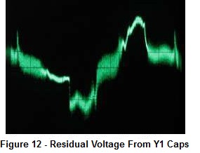
Figure 12 shows the residual voltage developed across a 5.1k resistor between chassis and earth. This particular measurement was taken from a TV set-top box, and measures 3.8V peak to peak, or 0.86V RMS. 168uA isn't much current, but remember that without the 5.1k resistor the voltage is ≈115V RMS, and voltage peaks are about 160V (either polarity). The voltage is high enough to feel, and there is more than enough current available to damage an input circuit if it happens to be connected while the AC voltage is at (or near) its peak. Also, note the high frequency content (the thick fuzzy sections). This noise is injected into the signal common (earth), and can easily generate considerable noise in circuitry.
In particular, all mains noises - clicks, pops, whirring noises, etc., are injected directly into the earth (ground) circuit of the connected equipment. For low level signals (guitar effects pedals and phono preamps for example), external transformers are common to get rid of such noise, but using an SMPS will bring them back - probably much worse than if the transformer were inside the same housing. An initial test with a guitar amp showed that the noise level introduced by a switching supply connected to an effects pedal (aka 'stomp box') made the system unusable - the background noise level was increased by at least 40dB, going from the traditional slight hiss to a nasty (and loud) combined hum and buzz. A linear supply made almost no audible difference - perhaps a couple of dB at the most.
The available current caused by the Y1 caps is small, but many people have reported getting a tingle or a bite from such equipment. With 230V mains, the current is only about 75 to 200uA - in theory, this should be below the threshold of feeling. Should you make a solid equipment connection right at the peak of the AC waveform, an instantaneous current spike is available, limited only by series resistance. The spike can easily be well above the current needed to destroy any opamp's input circuit or even a sound card output.
The instantaneous current depends only on the impedance of the wiring, and can exceed several amps if the impedances are all low enough. Note that the current spike also has the ability to damage the output circuit of an FM tuner, CD player, or other signal source. Needless to say, damage so-caused will not be covered by any guarantee. Even where a resistor is used on the output stage (typically 100 ohms), you can still get a 1.6A peak current if you connect at the peak of the AC voltage.
The current spike can easily remain above 1A for around 60ns, and since there is a peak voltage of over 160V available at the time, it has enough energy to cause real damage. Many people have been caught by this just using double insulated A/V equipment with an internal SMPS, and as transformer based units disappear the problem will get worse. Although there is a tiny amount of capacitance between the mains and secondary of a small (conventional) transformer, it is dramatically less than that from any SMPS using the caps. Measured voltage with a 10Megohm oscilloscope probe showed less than 10V RMS with any linear supply I tested, and was only a slightly distorted sinewave with no HF noise of any consequence. Compare this with 120V RMS from an SMPS tested the same way!
This is yet another annoyance - doubly annoying if it damages an expensive sound card or other signal source. There are already plenty of complaints on forum sites where exactly this problem has occurred, and they will become more common as transformer based supplies are phased out.
You can be excused for thinking that the peak voltage available is half the peak AC voltage, so for 230V mains, the peaks are 325V, and the maximum voltage at the supply output is ~160V ... sound right? Actually, that's maybe - if you are lucky. There's a big 'but' in there though, and it talks a bit of lateral thinking to get there.
Imagine that as you make the connection, a momentary contact is made at the peak of the waveform. You get a tiny (usually invisible) arc, and that seems to be the end of it. Unfortunately, what has really happened is that the Y1 caps have now charged up. Should the next momentary contact be made at the opposite AC peak, you have the full 340V available. This is best shown with a simulation, because even a 10Megohm oscilloscope input causes the voltage to collapse too quickly ...
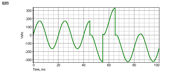
Figure 13 - Voltage at DC Output of SMPS
The voltage seen at the beginning is the normal output, as set up by the capacitors. At 45ms, the DC output of the supply is momentarily connected to earth via a resistance. You can see that the entire waveform then shifts downwards, because the capacitors are now charged with DC (which causes the offset). At 55ms, the output is again momentarily connected, but instead of the expected 170V, there is now 340V ... the caps are charged to 170V DC, and have an additional 170V from the AC supply at the waveform peak. There are three brief connections shown (45ms, 55ms and 65ms), after which you can see that the residual AC waveform now varies between close to zero volts and -340V. This will remain for as long as the caps stay charged - a few seconds at least. The DC component can range between zero and 170V, depending on the exact time of the last contact.
It is actually surprisingly easy to achieve this as you insert a connector into its socket. There are invariably short periods of connection and disconnection when any circuit is connected or disconnected. For this very reason, 'de-bounce' circuits are needed for digital inputs that are activated by mechanical switches. Whether you manage to make the connection without damaging something is purely a matter of luck, and if you rely on luck, it will run out some day.
In case you are wondering ... this isn't weird science or conjecture of any kind, just physics doing what it must.
A very basic (and admittedly rather crude) test was performed on a BC546 transistor. These are fairly rugged small signal devices, and one would expect them to be pretty immune to most external influences - after all, it is rare in the extreme for one to die unless severely overloaded. As a 500mW transistor with a maximum collector current of 100mA, it is vastly more rugged than any opamp input device. I tested the gain at 125, then subjected the base to a few touches of the earth (negative) side of the output connector of a small (unearthed) SMPS. The transistor's emitter was earthed, and transistors are used in much this fashion as 'real world' interfaces to digital circuits because they are so hard to destroy.
After the test, I checked the gain again - it had dropped to 30. The transistor had been ruined, simply by connection to an external switchmode supply. Other tests would reveal that noise performance would most likely also suffer, but there's no point if the transistor is rendered useless anyway. Had this transistor been used as an 'indestructible' interface to a piece of earthed equipment (Unit A), then connected to something else powered by an SMPS but not earthed (Unit B), that would be the end of Unit A - it's input circuit has been destroyed simply by making an otherwise perfectly normal connection as will be done by countless (and hapless) consumers who will be unaware of any likely problem. The packaging of any SMPS you will find certainly makes no mention of it as an issue.
It is a crude test, because no limiting resistors were used, but even a 1k 'protection' resistor would easily allow anything up to 340mA instantaneous base current - well in excess of the absolute maximum collector current specified in the data sheet (maximum base current is not specified, but is typically about half the peak collector current). Many input circuits have little or no protection components where discrete transistors are used, simply because there has never been any real need to do so in the past. Causing the emitter-base junction of a transistor to enter the zener breakdown region generally causes loss of gain and increased noise.
A second transistor was tested the same way - its gain fell from 150 to zero!
If a discrete bipolar transistor can be killed so easily, then we can take it as read that bipolar input opamps will also be killed because the transistor element in the IC is much, much smaller than that of a discrete component. FET input opamps don't stand a chance - even with typical protection circuits in place (usually just a series resistance at the opamp's input). This protection has always been sufficient before, but may not be enough if linear supplies are no longer available.
While this is happening, US chip makers are claiming that the existing ESD (electrostatic discharge) limits and the level of protection they need to include are arcane, outdated and 'overkill'.
The Industry Council on ESD Target Levels is working on a white paper at the International Electrostatic Discharge Workshop, which convenes 14-17 May in Lake Tahoe, CA, in support of a proposal to reduce on-chip ESD stress target levels by more than half. The reduction is supposed to lower cycle times and costs for chip makers, who are struggling to meet the current ESD levels in new designs. According to the council, those levels are outdated and represent 'overkill', causing unnecessary debugging time, IC redesigns and product delays. The group maintains that its proposal will not compromise quality or performance. See EETimes article for more details. Of course, product makers are complaining that the IC manufacturers just want to make ESD protection someone else's problem. Given that the ESD from a switchmode supply using Y1 caps for EMI compliance can kill a BC546 discrete transistor, the tiny devices used in many ICs don't stand a chance.
So, two BC546 transistors were completely destroyed by 'zapping' their bases from the ground lead of a small SMPS. What else? I also tried a few opamps - 2 LM4558 ICs died in the interests of testing, as did a TL072. The test jig was wired up on a piece of Veroboard, and each half of the opamp was configured with a gain of 2 (using 10k resistors) and with a 10k resistor from the non-inverting inputs to ground. Outputs were isolated using 100 ohm resistors.
No input stages survived being touched a few times with the ground lead of the SMPS. The common failure mode for the LM4558 opamps was that the output would swing to the positive supply. The TL072 was the opposite, but this is not necessarily what will happen every time. Opamp outputs actually survived with the 100 ohm resistor in place, but the spikes were very visible on the oscilloscope. It is probable that some degradation would occur with each zap, so while the device may survive initially, it will have reduced performance and will fail sooner rather than later.
When the same test was run without the 100 ohm output resistor, the outputs of both opamp types could be killed easily enough. A few touches with the ground lead of the SMPS was all it took. Output stages are naturally more robust than input sections, but they still died.
Including series resistance in output stages is recommended procedure to prevent oscillation, but including resistance in input stages can cause an increase of noise (because of the higher effective input impedance). While many of the projects on the ESP site use series input resistors, they are generally fairly low values (between 1k and 2.2k). From the tests I did, this is enough to save the input stage of even the FET input stage of the TL072 - at least for a rather limited number of test zaps. I did not test for increased noise levels.
The opamps tested are old technology, and are much simpler and more robust than those used in large scale integrated (LSI) circuits. I didn't test a CMOS device. These are fairly robust with simple logic ICs, but even then are known to be static sensitive - far more so than analogue opamps. Modern ADC and DAC chips will be far less tolerant because of the ever decreasing size of individual components in LSI designs.
I am playing 'devil's advocate' quite deliberately here. The failure modes described may be 1 in 1 million or less, but that's one too many. A linear external supply is generally considered to be extremely safe, in that there is no likely failure mode that can make the supply a potential death-trap. I have never heard of an injury, fatality or fire caused by the failure of a linear power supply, because they are so simple that full protection is easily accomplished with minimal difficulty or cost penalty.
Something that is an unknown at present is the end of life failure mechanism for small SMPS. I have seen many switchmode supplies (in equipment) that have failed in a rather spectacular manner, but there are few indicators at present as to what typical small SMPS will do when they fail. Because of the number of parts involved, it is impossible for anyone to predict which one will fail first, and it is probable that there will be multiple different failure mechanisms. Although the specific details have not been made public, there was a fatality in Australia in 2014 when a young woman was electrocuted by a mobile phone charger. Other fatalities worldwide have also been reported.
The worst-case is for an electrolytic capacitor to explode. This is not at all uncommon, and the results can vary from nothing else happening, to scattering burning paper and shredded aluminium foil throughout the equipment. Having seen both on a number of occasions, I know that either is possible. Should paper and foil be scattered throughout the confined insides of a small SMPS, there is a chance that some of the foil could bridge the isolation barrier. Have a look at the photos (above) of the insides, and you can see that there really isn't very much clearance, so even a small piece of foil is enough.
Should this occur, the output could easily become connected directly to the live mains or the high voltage rectified DC - that this could be a fatal failure is obvious. Anyone coming into contact with the 'safe' DC output is at serious risk of electrocution. Leaking electrolyte from an electrolytic cap can easily have the same effect (it is conductive, and needs to be for the cap to function).
A very common failure for SMPS is for the output filter capacitors to dry out through progressive loss of electrolyte over the years. When this happens, the DC output voltage will develop a high ripple voltage, and the average DC voltage often increase (anything up to 4:1 is likely). Not only will this commonly destroy the connected equipment, but any remaining capacitors in the output circuit are now at risk of explosive failure or rapid venting of electrolyte. No (cheap) SMPS I have encountered so far appears to have any protection whatsoever from an output over-voltage failure that could result in either severe internal damage to the supply itself or to the external device being powered.
Two notable SMPS failures I have experienced recently involved the internal supply for a PC and a DVD player. In both cases, the output voltage failed high - killing the PC motherboard and the entire DVD player's internals. The PC supply (and this was only the auxiliary 5V supply section - the PC wasn't even turned on at the time) generated a great deal of charred PCB material, as well as soot and smoke. It also managed to destroy a substantial protective diode on a disk drive. Is there anything in a small external SMPS to prevent the same thing happening? Not that I've seen so far. The extra circuitry needed will increase the cost and requires extra PCB space - two commodities that are at a premium for low cost devices.
Quite frankly, I don't consider the circuitry or isolation barrier provided in any external SMPS I've seen so far to be sufficient to prevent a breach, regardless of how the device chooses to end its life. There are just too many possibilities, because there are so many individual parts and so many different ways the supply can fail. The fact that supply failure can also cause the device it powers to fail adds yet another level of unpredictability. While a cordless phone (for example) may never be expected to fail in a spectacular manner with a linear supply, what happens when the supply voltage is doubled (or more) because of an external supply failure? I doubt that this has ever been tested, because at present there is no need to do so where a linear external supply is used.
I consider the two main issues to be possible electrocution and fire hazard. Apart from notebook PCs and a few other devices, the use of external SMPS has not been great up to the present. The supplies for notebook PCs are typically relatively expensive, but really cheap SMPS are fairly new so (at the time of initial publication - 2007) there are/ were comparatively few of them. Statistical data are pretty much non-existent ... search as I may, I couldn't find anything of any value. As noted above, the chance of either is low, but once there are millions of SMPS all made for the lowest possible cost in use, it's easy to envisage that a catastrophic failure is almost inevitable. Consider too that the PCBs used nearly always use the cheapest phenolic resin material available. I have yet to see a small SMPS using a fibreglass PCB, although few professional products use anything else.
While there is quite a bit of information on the Net regarding common SMPS failure modes, none that I saw included small supplies in the 1 - 50W range as will become common when the ban is imposed on 'low efficiency' linear supplies. The majority (predictably) refer to computer supplies, or TV, DVD or power amplifier supplies. Almost all that you look at will state that there are many possible causes for failure, but some are more common than others.
We already have a deplorable situation with most small SMPS perfectly capable of killing equipment because of the Y1 caps fitted for EMI suppression. While the authorities insist that this is 'perfectly safe', I remain unconvinced. There are many cases worldwide of fake components, and Y1 caps (more expensive than most) are an almost certain target for counterfeiters at some stage. Why? Because they can make a quick profit. I simply cannot foresee a situation where these caps will always perform perfectly forever, regardless of anything.
With a conventional transformer, there is a large and highly visible isolation barrier between the primary and secondary. Even if this were breached, the wires used to wind the transformer are insulated as well, and each winding is covered with more insulation.
In a SMPS, there is a small (and usually hidden) barrier in the transformer, which could have an inherent fault that can't be seen when the supply is built. The isolation barrier is bridged by (usually) an opto-coupler to provide feedback for regulation. It is also commonly bridged by one or two Y1 rated capacitors - again, no-one knows what's inside the package. The PCB isolation barrier is a bare section of (cheap) PCB substrate, with sections hidden under the transformer and opto-coupler ... perfect places for moisture (e.g. leaked electrolyte) to accumulate. Many small SMPS use slots in the PCB to increase the creepage distance beneath opto isolators and 'Y' caps, and sometimes beneath the transformer as well. This helps eliminate moisture build-up, but the barrier can still be breached by conductive materials jettisoned from blown electrolytic capacitors.
I have great difficulty accepting that the SMPS 'equivalent' to a conventional transformer can possibly be electrically safe to the same standards. Having worked with electronics all my life, I know that there are just too many possibilities for a failure. The regulators obviously have a much higher opinion of the inherent safety of every single component ever made than do I (or any other person who has serviced a failed electronics device).
This was a work in progress, but as of well before May 2014 (the date this page was updated) all external supplies that are subject to the MEPS requirements are now switchmode. AC plug-packs are still available, but all 'traditional' DC supplies are now off the market in Australia. Some of the new switchmode supplies are pretty good, although they all suffer from high frequency noise. As is to be expected, there are some that quite clearly don't meet mandatory safety standards, and these are nearly all due to small-scale importers who sell on auction sites.
Web searches will find instances of equipment having been damaged, and it can be difficult to determine if such damage is the result of Y-Class caps discharging into input circuits. It is a real and known issue to many technicians, but it is unrealistic to expect the average consumer to understand the possible risk, and doubly so if it's not spelled out in the instructions ... I've not seen it yet - some state that the equipment should be connected before the power supply, but no reason is given.
There are some similarities between this article and the CFL vs. incandescent lamp debate, but the difference is that here we are talking about much smaller savings and the potential for much greater risk to equipment. The effective elimination of AC external supplies is of particular concern, although these have not been affected so far.
There is some hope though ... alternative cores for conventional transformer based units exist, and it is certainly possible to make transformer supplies comply with all the requirements. The big question at the moment is whether anyone will do so. Only time will tell.
As noted in the amendment at the top of this page, some of the most arcane parts of the proposal were not included (so we still have iron cored AC-AC supplies), but I have seen an alarming increase in the number of untested and unsafe products available for sale - particularly on-line auction sites. As noted in the PSU Wiring article, there are some serious breaches of the Australian Electrical Safety Acts (each state has it's own for reasons that are entirely obscure).
An excerpt ...
Some overseas manufacturers (use your imagination as to which country might be responsible) have even decided not to bother with the nuisance of Y caps, and I have seen standard 1kV ceramics used in this role. This can only be described as very scary - especially since anyone can become an importer these days, and sell on auction sites. Most are completely unaware of mandatory requirements which vary from one country to the next, so no safety tests are performed at all.
These power supplies (all external PSUs in fact) are prescribed articles in Australia, and are subject to mandatory electrical safety testing. Because people implicitly trust the power supply not to kill them (a not unreasonable expectation) it's important to ensure that it won't. The tests are designed to ensure to the best of anyone's ability that no failure can cause the output or any exposed metal to become live, and that the PSU cannot catch on fire, emit smoke, or melt the casing to expose live parts.
I don't know about you, but I don't trust a foreign manufacturer who is desperately trying to sell for the lowest possible price. I know that thermal fuses will be missing (I haven't seen one in any of the cheap supplies), and that shortcuts will be taken. This includes using unapproved (or downright unsafe) parts, very basic circuitry with mediocre performance, and inadequate creepage and clearances between mains (hazardous) voltages and SELV (safety extra low voltage).
Electrical Safety Regulations for Australia | |
|---|---|
| Australian Capital Territory :- Electricity Safety Act 1971 - Sect 27 Electricity Safety Act 1971 - Sect 27 |
New South Wales :- Energy and Utilities Administration Act 1987 |
| Queensland :- Electricity Regulation 2006 - Sect 162 |
|
| Victoria :- Electricity Safety Act 1998 - Sect 68 - See "supply" Electricity Safety Act 1998 - Sect 3 - See "supply" |
Western Australia :- Electricity Act 1945 - Sect 33E Electricity Act 1945 - Sect 33F |
Please note that these are just a few of the regulations that may apply. It is certain that there are others, but the above should keep everyone entertained for minutes at a time 
 Main Index
 Articles Index