
|
|
| Elliott Sound Products | Electrical Safety Requirements |
 Main Index
Articles Index
Main Index
Articles Index
Contents
The requirements for electrical safety are (perhaps surprisingly) fairly consistent world-wide. European standards are now the basis for many others, and most of the definitions are (close to) identical no matter where you are. These definitions are important, because they determine the safety rating for any given piece of equipment. The standards of many countries were fairly lax until around the 1970s, but even after that they were often poorly enforced. A great deal of older equipment is positively (and negatively  ) dangerous, with some 120V equipment becoming potentially lethal if used at 230V without appropriate safety modifications (see 'death capacitor').
Most DIY people make their own power supplies, but there are also many who rely on external 'plug-pack' supplies (aka 'wall warts') or wall transformers. This is often done to ensure electrical safety, especially by newcomers who are not comfortable with (or qualified for) working with mains wiring. It's not at all uncommon for 'nanny state' regulations to make it difficult to get the parts needed, and (more importantly) it's close to impossible to get a copy of the necessary standards that apply where you live. In most cases, they are only available if you buy the standards documents, and this can get very costly, very quickly.
It can even get confusing if you need (for example) a small (probably switchmode) power supply that's totally isolated from hazardous voltages. this may be to provide power to a small electronic device, or perhaps as an auxiliary (always-on) supply inside equipment to control switching or retain memory settings. The voltage needed depends on the purpose, but will typically be somewhere between 5V and 24V DC. It's not always easy to know if a particular power supply or other piece of gear is not only safe, but legal where you live. Most supplies purchased from reputable suppliers are safe, but ebay is a one-stop-shop for many people, and the goods sold are often poorly described, with little or no safety information. Many items (especially direct imports) do not comply with any standards, and a few have been proved to be lethal during coroner's inquests!
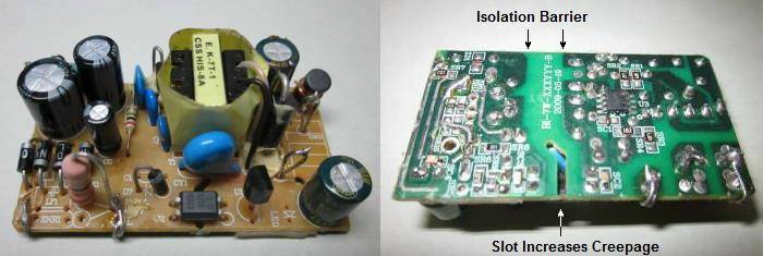
The photo shows the (modified) intestines of a switchmode supply that was removed from a plug-pack ('wall-wart'). It was intended to be used inside another piece of equipment where an external supply was not considered acceptable, and I used an Australian approved plug-pack to get the PCB. The various points of interest are shown on the photo, including the isolation barrier and the slot used to increase creepage distance under the optocoupler, between the mains (hazardous voltage) and the output (extra-low voltage). The outer case (now discarded) had the required Australian approvals moulded into the plastic. Although it is modified, no changes were made that could cause the electrical safety to be compromised. However, to retain safety, it has to be installed in such a manner that it can never become detached, and that even if it did become detached it would still remain safe.
We expect to see standards markings, such as a C-Tick (AS/NZS compliance for Australia & New Zealand, now called RCM - regulatory compliance mark), BS (British Standard), UL/CSA (US, Canada), CE, IEC (Europe), VDE (Germany). Many of the 'far eastern' suppliers do not actually run any tests at all, let alone have tests done in a certified laboratory (as required by all standards bodies). The certifications may well be imprinted on the supply, but that does not mean it is actually compliant. There have been deaths in many countries as a direct result of non-compliant power supplies (especially phone chargers) bought at markets or from on-line auction sites. Some of these will claim compliance, but have never been tested. Not only have they not been tested (or 'classified'), but there are many that will fail (often spectacularly) if tested to any relevant standard.
There are countless examples of fake 'name brand' phone chargers on the Net, and while some might be alright, many are not. There have been cases worldwide where people have died or been injured because of fake (and non-compliant) phone chargers that have failed and placed the full mains voltage on the output. Without exception, these fakes are bought from on-line vendors on auction sites, or from 'pop-up' market stalls where someone has imported them to sell. In Australia, there are often raids performed by compliance officers on market stalls, with non-approved and potentially unsafe products seized and destroyed (and the vendors fined). Be aware that many media (especially social media!) reports and/ or claims show only that the writer has no understanding of how any electrical equipment operates, so reports can be (and often are) somewhat non-sensical. Such 'advice' should usually be discarded.
Equipment classes divide electrical appliances and other sub-systems into different classes. These describe the safety arrangements that apply (or not), and in some cases the claimed class may not match reality. Medical classes are (generally) the same as the other classes used for non-medical equipment, but most countries only allow for Class I (using a safety earth), Class II (double or reinforced insulation) and/ or Class III (safety extra-low voltage). These are discussed in greater detail below.
While this article is primarily about insulation, equipment classes and requirements for safety isolation, it's also important to understand the implications of frequency. With most modern gear using a switchmode power supply it's not an issue, but it's something that must be understood for transformer based supplies and some electric motors. See Importing Equipment From Overseas ... Effects of Voltage & Frequency on Electronic Equipment. You may also want to read the article Electrocution & How To Avoid It, which also covers some of the info shown here.
Commercially made mains powered equipment that's only a few years old will generally be to a reasonably high standard in terms of electrical safety. In most countries, it is a requirement that mains wiring cannot be accessed by the user without the use of a tool (which can be as simple as a screwdriver). It's common now for security screws to be used to make it harder for anyone to get inside. IMO this is silly, as non-technical people don't want to get in, and technical people will get in regardless. A great deal of new equipment is double insulated, and no earth wire is used. A 2-pin plug, 2-core mains lead and wide-range power supply allow operation world-wide, and only the mains lead has to be changed to suit the importing country's mains outlets.
In this article, I have used the normal Australian terms for mains conductors. These are 'active' (aka phase, line or live), 'neutral' and 'earth' (protective earth, earth ground, ground, etc.). The terms differ world wide (as do the colours used), but it's generally hard to be confused because the terms are fairly self-explanatory. Two terms that are not very sensible are 'grounded conductor' (neutral) and 'grounding conductor' (earth). These terms are sometimes used in the US, but are not used elsewhere.
There are literally countless documents, standards and pieces of legislation that cover electrical products worldwide, and I cannot possibly even try to list them all, nor can I provide country-specific information. There are rules and regulations not only for equipment, but for mains leads and connectors, how they must be marked, and whether or not they specifically require individual type approvals. This varies widely in different countries, in some cases approved test houses must test and certify the product, and in others only a 'declaration of suitability' or similar may be required. In some places it may be illegal (or at least unlawful) to perform mains wiring of any kind unless licensed by the appropriate authority, while in others it's quite alright. It's entirely up to the reader to determine what is or is not permitted whey they live - I can't (and won't) even attempt this.
It's also important that the reader understands that this article covers only the electrical safety aspects of an electronic circuit. There are other regulations as well, covering EMC (electromagnetic compatibility), which places defined limits on the radio frequency noise, including radiated and conducted emissions. Radiated emissions are those that can be picked up by a nearby radio receiver, and conducted emissions refers to noise passed back into the electricity grid via the electrical outlet. Linear power supplies (using a conventional mains frequency transformer) and approved switchmode supplies will generally pass both tests, but a switchmode supply you make yourself (not advised) or one purchased from ebay probably will not.
There are additional regulations that cover the risk of fire, and in many cases tests are conducted on plastics and other materials to ensure they self-extinguish once the heat source is removed. These test may or may not be mandatory, or will be required for some products but not for others. This is a minefield, and again, to get the proper information you need to purchase a copy of the relevant standard. In most cases, you won't even know which document(s) you need to buy, and even trying to find out will result in many hours of frustration.
Electrical appliances using mains voltage must (in most countries) provide at least two levels of protection against electric shock to the user (e.g. double-insulation). This ensures that if one of the protection layers were to fail, there is a back up (the second layer) still in place. Provided all external wiring is up to standards, this makes electrical equipment safe to use. Insulation classes are also subject to temperature limits.
Functional Insulation between conductive parts which is necessary only for the proper functioning of the equipment Basic Insulation applied to live parts (e.g. the plastic insulated connectors that hold the active and neutral wires in place) to provide basic protection against electric shock Supplementary An independent insulation, in addition to basic insulation, to ensure protection against electric shock in the event of failure of the basic insulation Double Insulation comprising of both basic and supplementary insulation Reinforced A single insulation system applied to live parts, which provides a degree of protection against electric shock equivalent to double insulation
In the electrical appliance manufacturing industry, IEC (International Electrotechnical Commission) protection classes are used to differentiate between the protective-earth connection requirements of devices.
Depending on how the protection is provided, electrical appliances are put into five classes of equipment construction, Class I, II, III, 0 and 01. Of these the most important (and generally the only ones that are relevant for modern equipment) are Class I and II. For historical reasons, Class 0 is also covered. Class III is uncommon, at least as officially specified, but many products could be designated as Class III if supplied with a compliant transformer or power supply.
The temperature rating of insulation is important, and failure is almost certain if it's exceeded. Such failures are rarely instantaneous, and in some cases it may take several years for the materials used to degrade to the point where they are no longer insulators. All insulating materials will break down at elevated temperatures, and the enamels and resins used in power supply transformers and/or PCBs are generally fairly low temperature. The list below shows some of the temperature classes (based on IEC thermal classifications). Letter codes are also used, and can be found on-line easily enough. Those shown are the IEC (60085 Thermal Class) numerical codes, which make a lot more sense than letters (with gaps!).
90 90°C Paper (not impregnated), silk, cotton, vulcanised natural rubber, thermoplastics that soften above 90°C 105 105°C Organic materials such as cotton, silk, paper, some synthetic fibres 120 120°C Polyurethane, epoxy resins, polyethylene terephthalate (PET/ Mylar®/ Polyester) 130 130°C Inorganic materials such as mica, glass fibres, asbestos¹ with high-temperature binders 155 155°C Class 130 materials with binders stable at the higher temperature 180 180°C Silicone elastomers, and Class 130 inorganic materials with high-temperature binders 200 200°C Mica, glass fibres, asbestos¹, Teflon® 240 240°C Polyimide enamel (Pyre-ML) or Polyimide films (Kapton® and Alconex® GOLD) ¹ Asbestos was common, but due to the damage it causes to lung tissues it is no longer used in any 'normal' application. It might still exist in old equipment, so beware.
The ambient temperature must be considered as well. In all cases with electronic parts, the ambient temperature is that measured in the immediate vicinity of the part, and not the temperature inside the room, building etc. All insulators should be operated at the lowest feasible temperature, but usually not below 0°C unless unavoidable. Most common power supplies and transformers will be rated for no more than 120°C maximum temperature, with switchmode supplies generally lower (105°C is the upper limit set by electrolytic capacitors).
Most insulation failures are the result of age and temperature. When built, a 50 year old transformer used materials that may no longer be considered safe, but if used within its ratings it can easily last for another 50 years without risk of failure. While short term overloads are (generally) easily tolerated, repeated or prolonged abuse will reduce the life of a transformer. So-called 'hot spotting' (where one part of a winding gets much hotter than the overall/ average) can reduce a transformer's life significantly. Mechanical damage can cause a failure by physically breaking the insulation between windings or from a winding to the core.
Conventional 50/60 Hz transformers are incredibly reliable when used sensibly, and even after 50 years (or more) most can be relied upon to perform as expected and remain safe to use. Modern switchmode supplies have much greater complexity, and the life is not related to the transformer, but the support components (ICs, transistors and especially electrolytic capacitors). Because there are so many more parts, there are many more things that can go wrong. Elevated temperature shortens the life of all parts, and the maximum ambient temperature should be kept as low as possible. This is not always easy.
The insulation requirements extend beyond the transformer and associated parts (where used). Other wiring can degrade or be damaged as well, and the mains wiring in old valve equipment is especially vulnerable. The heat inside the chassis can cause accelerated degradation, particularly where the insulation is vulcanised rubber or low-temperature plastic. This is especially important for original Class 0 equipment (see next section) where the only level of protection is basic insulation with no backup of any kind.
A brief rundown of some of the equipment classes and applicable standards follows. These are important to understand, as mis-application can result in equipment that is unsafe, with the risks of electric shock, fire or both. The standards applied vary by country, but most use the following definitions and requirements.
Class 0 Electric shock protection afforded by basic insulation only. No longer allowed in most countries for new equipment, but 'legacy'/ vintage gear is commonly Class 0 (especially that of US origin). Unsafe, and should be upgraded to Class I without delay. Class I Achieves electric shock protection using basic insulation and protective earth grounding. This requires all conductive parts that could assume a hazardous voltage in the event of basic insulation failure to be connected to the protective earth conductor. Class II Provides protection using double or reinforced insulation and hence no ground is required. Class III Operates from a SELV (Separated Extra Low Voltage) supply circuit, which means it inherently protects against electric shock, as it is impossible for hazardous voltages to be generated within the equipment.
The markings shown above are not entirely 'universal', but are standard for Australia (& New Zealand) and most of Europe. It is mandatory in most countries to show the Class-II (double-insulated) symbol for equipment so designated, but Class-I gear will usually have no markings - it will be supplied with a 3-core IEC lead (or fixed 3-core lead) that removes any doubt. Note that in most countries, leads with a 3-pin IEC connector must also be fitted with a 3-core lead, for active, neutral and earth, and a matching 3-pin plug on the other end. This must also be followed if you make your own lead, because it's potentially very dangerous to have an IEC lead without an earth wire, because it can be used with any equipment fitted with a matching IEC receptacle, including gear that must be earthed. The current rating of the cable must match that of the plug and socket (10A for an IEC C13 socket). All connectors and cable should be approved for use in the country where you live.
Understanding the safety standards and the above classes of equipment requires a clear understanding of the circuit definitions, types of insulation and other terminology used in relation to power supplies. There are (according to some sources) sub-standards of the above, such as Class 0 (basic insulation, no provision for a safety earth) but these do not exist in any standards documentation that I've seen, and should not be used.
However, many 120V countries have been using 'Class 0' for decades, where the insulation class is 'basic' (i.e. not reinforced) and no protective earth (ground) is provided by the mains lead or plug. Countless guitar amplifiers, pieces of hi-fi gear and other appliances are still in service that can only be classified as 'Class 0', and while passably safe when used at 120V AC and in dry conditions, such equipment is decidedly unsafe at higher voltages (such as 220-230V mains). The sale of such equipment is now generally unlawful in most countries, but so-called 'grandfather' clauses in regulations may allow this gear to co-exist with Class I and Class II. In general, any Class 0 gear you have should be upgraded to Class I to ensure it doesn't kill anyone (including you).
The idea of 'protection' being afforded by (aging and possibly disintegrating) basic insulation with absolutely no backup (no safety earth or reinforced insulation) is not something to inspire confidence. Such equipment is inherently dangerous, and doubly so if it's been modified for 230V but without adding an earth connection. Various US guitar amp makers went the extra 'mile' to ensure that the danger was as great as possible, by including what has become known as the 'death cap' (no, not the mushroom). This was nearly always just a high voltage (typically 630V DC, and around 39-47nF) capacitor connected to the (unearthed) chassis by a switch. The user could select the switch position that gave the least noise (or perhaps the milder electric shock). This topic has its own section below.
Note that Class 0 products will be prohibited from sale in most countries. No new equipment should use this class, and existing equipment is expected (but unfortunately not mandated) to be upgraded to Class I. I've not mentioned Class 01, but that's also prohibited. Class 01 refers to products that have provision for an external earth (protective or functional), but it's not connected via the mains cable. For example, vintage radios (almost always AM) often had an earth terminal on the chassis, but used a two-wire mains lead. The earth terminal was often used in conjunction with an external antenna to improve reception.
This is something of a can of worms. World-wide, there are many different standards, and detailed info is mostly available from the standards documentation, which is only ever available if you pay for it. The test voltage is usually DC, but 'hi-pot' (high potential) tests are also done with AC. This is one of the areas where head-scratching and general confusion are the only sensible options. While a product (such as an isolation transformer or DC-DC converter) may claim it has been tested at 1kV, that does not mean that it can be used at that voltage. In some cases the actual recommended voltage might be less than 100V RMS.
Some parts (such as optocouplers) are specifically designed to provide a high isolation voltage. Common devices are rated for 7.5kV AC isolation, which is far more than can actually be used on a normal PCB. These parts are used extensively in switchmode supplies to provide voltage feedback, and they typically can have the full mains voltage across the isolation barrier. It's a great deal harder to maintain high isolation with a wound component (i.e. a transformer), because there may be air pockets between windings, and the windings have to be physically segregated while trying to keep package dimensions to the minimum. Now, two more terms come into play - creepage and clearance. These will be covered later.
| Cable/Equipment Operating Voltage | DC test voltage |
| 24 to 50 V | 50 to 100 VDC |
| 50 to 100 V | 100 to 250 VDC |
| 100 to 240 V | 250 to 500 VDC |
| 440 to 550 V | 500 to 1000 VDC |
Hi-Pot tests can be destructive. In such a test, the test voltage is increased until the insulation fails, which gives an indication of the dielectric strength of the insulation material. Non-destructive tests are at a lower voltage, and verify that the part or product meets specifications. Test times range from a few seconds to 1 minute or more.
| Material | Dielectric Strength |
| Vacuum (reference) | 20 - 40MV/ metre |
| Air (Sea Level) | 3.0MV/ metre |
| Aluminium Oxide | 13.4MV/ metre |
| Ceramic | 4-12MV/ metre |
| Kapton | 120 - 230MV/ metre |
| Mica | 160MV/ metre |
| Polycarbonate | 15 - 34MV/ metre |
| Polyethylene | 50MV/ metre |
| Polyester/ Mylar/ PET | 16MV/ metre |
| Polypropylene | 23 - 25MV/ metre |
| Polystyrene | 25MV/ metre |
| Teflon | 60 - 150MV/ metre |
Dielectric strength values are not exact, and it's surprisingly hard to get hold of anything definitive. The above table was taken from the ESP article on capacitors. It's common (but not very useful) to specify dielectric strength in V/m (volts per metre), and that's what is shown in the table. To get something meaningful requires some simple maths. Volts/ µm (micrometre) is easy, simply call the value shown 'volts' instead of MV. For example, polyester/ PET has a dielectric strength of 16V/µm, so a 25µm film can withstand 400V. The US generally uses the 'mil' (1/1,000") which is close enough to 25µm.
The voltage depends on many factors, including the thickness of the film, the shape of the electrodes used for the test and the temperature of the material being tested. The rise-time of the test voltage also affects the result, so test systems have to comply to the relevant standards. ISO/IEC standards specify a material thickness of 1mm for testing.
The most common and best known insulation (dielectric) tester is the Megger ®, which has been used to verify electrical installations for many, many years. For 230V installations, the recommended test voltage is 500V DC, and the insulation resistance of a circuit must exceed 1MΩ. These testers can also be used for components (transformers, isolators, etc.) and are now readily available with multiple test voltages. Of course, the latest ones are digital and use a switching supply to generate the high test voltage.
Power supply voltages are categorised depending on voltage and type of supply (AC or DC). The vast majority of DIY power supplies for power amps and preamps will include 'Hazardous' voltages (all mains wiring) and 'ELV' (extra-low voltage) for both power amp and preamp supply voltages. Some power amplifiers have supply rails that exceed the ELV ratings (and they can provide an output voltage that also exceeds ELV), but there is no consensus worldwide as to whether this constitutes a hazard or not.
Hazardous Voltage Any voltage exceeding 42.2V AC peak or 60V DC without a limited current circuit. Extra-Low Voltage (ELV) A voltage in a secondary circuit not exceeding 42.4V AC peak or 60V DC, the circuit being separated from hazardous voltage by at least basic insulation. Separated Extra-Low
Voltage (SELV)A secondary circuit that cannot reach a hazardous voltage between any two accessible parts or an accessible part and protective earth under normal operation or while experiencing a single fault. In the event of a single fault condition (insulation or component failure) the voltage in accessible parts of SELV circuits shall not exceed 42.4V AC peak or 60V DC for longer than 200ms. An absolute limit of 71V AC peak or 120V DC must not be exceeded.
SELV circuits must be separated from hazardous voltages, e.g. primary circuits, by two levels of protection, which may be provided by double insulation, or basic insulation combined with an earthed conductive barrier.
SELV secondaries are considered safe for operator access. Circuits fed by SELV power supply outputs do not require extensive safety testing or creepage and clearance evaluations.
Limited Current Circuits These circuits may be accessible even though voltages are in excess of SELV requirements. A limited current circuit is designed to ensure that under a fault condition, the current that can be drawn is not hazardous. Limits are detailed as follows: To qualify for limited current status the circuit must also have the same segregation rules as SELV circuits.
- For frequencies < 1kHz the steady state current drawn shall not exceed 0.7 mA peak AC or 2mA DC. For frequencies above 1 kHz the limit of 0.7mA is multiplied by the frequency in kHz but shall not exceed 70mA.
- For accessible parts not exceeding 450V AC peak or 450V DC, the maximum circuit capacitance allowed is 0.1µF.
- For accessible parts not exceeding 1500V AC peak or 1500V DC the maximum stored charge allowed is 45µC and the available energy shall not be above 350mJ.
The above may look either straightforward or complex depending on your experience. It's probably more complex than it appears, because all of the terminology relies on insulation and equipment classes. ELV isn't at all daunting, and that's what most of us will use for preamps and power amps, along with a great deal of other equipment. It is important to understand that the 'basic' insulation that separates ELV from hazardous voltages must be rated for the worst-case maximum input (hazardous) voltage, with an adequate safety margin to ensure longevity under adverse conditions. It's also important that no component failure can cause a breach of the safety barrier or create a fire hazard.
The term 'SELV' is claimed to stand for either 'separated extra-low voltage' or 'safety extra-low voltage', depending on the source. SELV (in its true form as defined by the standards) only applies when a fully compliant SELV transformer is used. While an off-the-shelf part may provide extra-low voltage, it usually can't be referred to as 'SELV' unless the transformer is an approved type. This is not possible in most cases, due to cost. The secondary of a SELV transformer is not connected to the mains protective earth - it is intended to be floating.
Limited current circuits are not common. An example is a 'touch' switch that operates only from the mains (no low voltage transformer), and these rely on a tiny current drawn as your finger touches the trigger plate to function. It should be immediately apparent that this type of circuit has to be carefully designed, and that current-limiting components must be totally reliable. They can become open circuit, but never short circuit. Class Y capacitors (preferably 2-3 in series) and high value, high voltage resistors are called for.
Medical applications are not covered here. These add significant restrictions to ensure patient safety, and also require extensive laboratory testing to verify compliance. This is an expensive process, and is not something that most people will experience. There's also no attempt to cover telecommunications requirements. This is another area where many things can change (including definitions) and it is complex and expensive to obtain approvals. While there are many similarities world wide, there are also some significant differences that make this a rather specialised field.
The Low Voltage Directive (LVD) is a European standard that covers health and safety risks with electrical equipment. Internal voltages are not part of the standard unless they are accessible from outside the enclosure, which would most commonly only be accessible by using a tool - a screwdriver is generally considered a 'tool' for the purposes of much legislation. For most electrical equipment, the health aspects of electromagnetic emissions are also covered by the LVD. The LVD applies for electrical equipment operating with an input or output voltage of between ...
50 and 1000 V for alternating current (AC)
75 and 1500 V for direct current (DC)
The LVD applies to a wide range of electrical equipment for both consumer and professional usage, such as ...
Luminaire plugs and socket outlets for domestic use
Appliance couplers, plugs, outlets
Cord extension sets Plug + cable + socket outlet, with or without passive components
Installation enclosures and conduits
Travel adaptors
Household appliances
Cables
Power supply units
Certain components (e.g. fuses or other safety-critical parts)
The EU legislation in this area is important to ensure that health and safety requirements are the same across Europe for products placed on the market. However, many other countries don't apply the same criteria, or they are applied differently. Some of the LVD requirements may be unique to Europe, but most other countries have rules that achieve the same goals. As always, if you need the full scope of the LVD you have to purchase the standards documents.
There is information available on-line, but you're unlikely to find any finer details such as the test methodology, scope of testing, or anything that's actually useful for someone building their own equipment. Adherence to basic safety guidelines will help, but even that can be difficult if you can't find the information anywhere. This is a recurring theme - to ensure compliance you need the detailed knowledge of the requirements, but you can't get that without paying the (usually hefty) price for the standards documentation.
These are two terms that most people do not understand. This is not surprising, because although they are self-explanatory, the explanations themselves don't mean anything without context. Clearance is the distance, through air, separating hazardous voltage from phase to neutral, earth or any other voltage. The minimum value is typically 5mm, but there is a vast variation depending on pollution categories (not normally applicable inside sealed equipment) and voltage. Using the minimum figure is not sensible for hobbyists, and it's preferable to ensure that the separation is as great as possible.
Creepage is the distance across the surface of insulating material, including printed circuit boards, plastic terminal blocks, or any other material used to separate hazardous voltages from phase to neutral, earth, or any other voltage. Again, 5mm is generally considered 'safe', but that depends on the material itself, pollution categories (again) and the voltage(s) involved. Note that the creepage distance is from the closest edges of PCB copper pads or tracks, and not the pins of the connector or other device. The following drawing shows the difference between creepage and clearance.
In the above, creepage is shown between two transformer windings (only the layer adjacent to the primary/ secondary insulation is shown). The second drawing shows creepage across the PCB and clearance between the wire 'cups' on a barrier type terminal block. Creepage exists on both sides of the board. Where pollution is expected, this may be able to bridge the creepage distance with partially conductive 'stuff', possibly allowing sufficient current to cause fire. Be aware that burnt materials (such as PCB resins) can become carbonised (and therefore conductive) if heated beyond their rated maximum temperature. I've seen it happen and it is a very real phenomenon, so you should withdraw your scoff immediately .
As with most of the other standards, you will only get those that apply where you live if you pay for the relevant documents. There is information on-line, and some of it has been 'extracted' from standards documentation. Other material you find may or may not be relevant or even accurate, so you need to do the best you can to ensure that creepage and clearance distances are as great as you can make them, without being silly. If at all possible, ensure around 8mm (0.315") for both creepage and clearance. Where space allows, greater distances may be used.
'Officially', the minimum clearance distance depends on the 'overvoltage category', which for 120/230V equipment is usually 4kV. Deciphering some of the info you may find (if you look hard enough) can be difficult, and designing for the minimum is unwise anyway. While you might get away with using the minimum, that doesn't mean that your project would pass lab testing. Items with a 4kV overvoltage category must allow a minimum of 3mm clearance between mains conductors, but IMO that would be less than ideal.
In some cases, switchmode power supply manufacturers place a cut-out slot beneath optoisolators and/ or transformers to increase the creepage distance (see Figure 1). This is potentially useful to avoid a conductive path between mains and low voltage if the PCB material become contaminated (for example, if an electrolytic capacitor loses its electrolyte). This is commonly seen in higher quality units, but not so much in 'budget' or non-certified supplies. Open PCB supplies (no casing) are commonly used within other products, and become an integral part of the overall unit, and if type approval is required the PSU is tested along with everything else.
It's important to understand that creepage and clearance distances are not limited to your wiring. Transformers are subject to the same constraints, as are small switchmode supplies, whether 'stand-alone' or sold as wall transformers (AC or DC). In Australia, all wall transformers (aka 'wall-warts') are 'declared articles' (formerly known as 'prescribed articles'), and safety testing is mandatory. That means they must be type-approved, and will be subjected to a barrage of tests (some of which may be destructive) to ensure that there is no single failure that can render the item unsafe. If the possibility of multiple failures is identified, then that will also be tested.
Most countries don't have such a rigorous approach, but all major countries do insist that products bear the appropriate safety standard markings for the country where it's sold. This is the responsibility of the manufacturer or supplier, and government agencies may demand to see the test results (perhaps on a random basis) to ensure compliance. Such demands will be made routinely if there is a reported injury or death attributable to the power supply in question. None of the fake 'name-brand' products will have been tested, and the required safety logos are simply applied to the product to make it appear legitimate.
For the average (or even skilled) user, it can be almost impossible to verify that the product really has been tested, but sometimes you can get a good idea if you can look inside. The use of 3kV ceramic capacitors instead of certified Class Y caps is not uncommon, some have almost laughable creepage and clearance distances, and others may actually look to be alright. However, without proper testing, you have no way of knowing if the insulation in a small switchmode transformer is up to standard, nor can you know if proper creepage distances are maintained between the windings (creepage and clearance do not apply if the transformer has been varnish impregnated). Where a transformer has been impregnated or potted, the standard test is the 'hi-pot' test, with the voltage increased to 4kV or more, depending on the insulation class claimed.
A part of most safety tests for Class I equipment (incorporating a safety earth conductor to the power outlet) includes verifying that the earth lead is capable of handling a reasonable current, and has a low resistance (typically 100mΩ, or 0.1 ohm). A test lab will use a dedicated tester for this, and PAT testers provide this function as well. The test is normally conducted at 1.5 times the power outlet rating (so 15A for a 10A outlet), with a maximum test voltage of 12V (AC RMS or DC). The maximum current is 25A.
This is not something that most home constructors will ever verify, but it is obviously important. There's no point including an earth lead that can't handle enough current to open a circuit breaker or blow a fuse. Elsewhere on the ESP site, I've provided a circuit for an 'earth loop breaker', which uses a high-current diode bridge in parallel with a 10 ohm resistor and a 100nF capacitor. Clearly (and as advised in the articles where it's shown), technically this will be unlawful in most countries if it's simply in series with the earth lead. If used, the 'loop breaker' should simply lift the common ground of the internal electronics, with the earth lead firmly connected to chassis (including the frame of the power transformer if it's a 'conventional' (E-I laminations) type). An example of this circuit is shown in the power supply of Project 27.
Even then, if one follows the letter of the regulations, this may still be unlawful, because there will be a 2V drop across the diodes if there is a primary-secondary transformer insulation failure. These are very uncommon, the risk is therefore small, and the diodes will pass the test current easily. However, the measured 'resistance' will be well in excess of the allowed 100mΩ, and the test may be deemed a fail, depending upon the test methodology used. The test methodology specifies that it's carried out between the earth pin on the mains lead, and any earthed (or intended to be earthed) metalwork or user accessible earthed contact points. Provided the input and output connectors are not claimed to be earthed, then the test should pass, but this may depend on the person performing the test.
When something 'unusual' is done (such as an earth loop breaker), there are several possible interpretations, and regulations may not consider such an arrangement to be an 'acceptable' practice. As far as I'm aware, this has not been verified one way or another with any authorised test house, so it's not possible to say with any certainty that it would pass required tests. As already noted, there may be something in the standards documentation that covers it, but I can't afford to purchase endless official standards documents, and nor can prospective constructors.
It used to be that only valve (vacuum tube) amplifiers had high internal voltages, but there are also many transistor amps that have a total supply voltage of well over 150V DC (±75V). This is not necessarily considered dangerous, but it can still give a nasty bite. Valve equipment has HV potentials of up to 700V DC, and occasionally even more. This is most certainly dangerous, and it's essential that the high voltage is properly 'contained' so that no-one can come into contact with it.
It seems likely that (some of) the possible dangers have 'slipped through the cracks' to some extent, since the regulatory bodies probably don't take much notice of niche products. If everything is enclosed in a 'cage' of some kind (or a perforated steel cover protects the valves) then there's no risk to the user, but much of this equipment has no protection. The user is separated from the HV by a very thin and fragile glass envelope, and if that is broken, touching the internal structure of a valve could be fatal.
Children are particularly vulnerable because they have no awareness of the danger. However, there don't appear to be any reported deaths associated with valve amps in general, but this is no reason for complacency. Valve equipment is especially dangerous when you are working it, and there's no-one I know who's never received a shock when working on valve amps if it's done regularly. Such shocks can be fatal, but are more often just very disconcerting and definitely get the adrenaline pumping.
It's obviously essential to ensure that all wiring is safe, and uses insulation that's designed to withstand the voltage(s) used. All forms of insulation (not just the wiring) need to be adequate, and there don't appear to be any specific regulations that apply to high internal voltages, provided they are inaccessible from outside the chassis. Some valve equipment (guitar amps in particular) uses the minimum possible insulation, but breakdown is rare and few faults can be traced to insulation failure. This doesn't include output transformers or valve bases and sockets, where insulation breakdown is not at all uncommon.
Due to the lack of readily available regulatory information, the only things I can recommend are based on common sense. While some form of protective cover for the valves themselves (especially output valves) is preferable to just having them in 'free air', this is uncommon, despite the fact that they get very hot and can cause serious burns if touched. Most users are aware of the dangers, and it's advisable to ensure that children are warned not to touch any valve equipment that isn't protected.
One thing I advise everyone to ensure is that you do not wear a ring, bracelet (including watch band) or long neck chain when working on valve gear. Rings and bracelets can get caught on parts of the chassis, making it hard or (perish the thought) impossible to withdraw your hand if you get a shock. Neck chains can touch (and/ or short circuit) high voltages, and can be very dangerous. Anyone who claims that you should keep one hand in your pocket to prevent a hand-to-hand shock (so current is passed through your heart) has never fixed anything, and is talking through his/her hat. You can't do anything useful with one hand. However, you must remain vigilant. It's almost certain that you will receive an electric shock at some time if you work on a lot of valve gear, and if you are careful and sensible you'll live to receive another .
Some people recommend the use of an isolation transformer. In a word ... don't! This is a myth that's been around for longer than I have, and it's flawed thinking at its worst. An isolation transformer should be used only if you are working directly with the mains (not the secondary voltages provided by a power transformer), and even then with extreme care. An isolation transformer completely disables your workbench safety switch (you do have one, don't you?), so if you touch the mains and something else in the chassis at the same time, the safety switch won't trip and you may be killed. When working on secondary voltage (e.g. valve amp high tension) circuitry, the isolation transformer does absolutely nothing to make it 'safer'. However, if you don't understand the proper usage of an isolation transformer you may become complacent - complacency and electricity are not compatible with life!
The 'death capacitor' (or Death Cap) was used in many guitar amps and early (AM radios, almost always those made in the US or intended for the US market. It's only comparatively recently that global trading has allowed these old guitar amps in particular to 'escape' to 230V countries in reasonable numbers. While the capacitor used was typically rated for 400 or 600V DC, the dielectric would usually withstand 120V AC without a guaranteed failure. That does not apply with 230V AC. Almost all DC capacitors will eventually fail if used across an AC voltage of more than ~250V peak (177V RMS). The reasons are complex and are not covered here, but the cap must be removed regardless of mains voltage.
When used as shown below, this practice is no longer permitted under any regulations in any country on earth, but there is also no specific requirement to remove it if found. The sensible technician will always remove the death capacitor and fit a 3-core mains lead with a safety earth and 3-pin plug. The non-sensible technician could find himself/herself at the wrong end of an unlawful death or manslaughter charge if someone dies because this deadly arrangement was left in place. Even when this practice was widespread, it was limited to 120V countries and as far as I'm aware it would have been unlawful elsewhere because it's so dangerous. It's now illegal in most countries, meaning this practice is specifically declared as something that is not permitted.
Consider that a 50 year-old guitar amp has 50 year-old insulation, and unless upgraded, that's something I'd trust almost as far as I can kick a piano. The easiest and least intrusive upgrade is to fit a 3-core mains lead, 3-pin plug, and earth the chassis securely with the green/ yellow (or just green) protective earth conductor. If fitted, the 'death cap' must be removed to ensure compliance with modern safety standards. While many owners of vintage gear often don't like making changes, safety must override all other considerations. Owning a completely original vintage amp that kills you is not something you should aspire to.
When the cap fails, the failure mode is almost always a short circuit, followed by the cap exploding and spreading metallised film everywhere.
Even today, there is argument on the Net as to whether the 'death cap' is a safe practice or not. A great deal has been written, and a much of that is either complete nonsense or shows that the author doesn't actually have a clue. It's unfortunate that anyone can post a video and claim to be knowledgeable in the field they discuss, when they actually don't know what they are talking about. There is one (and only one) answer to the question "Should the death cap be removed?", and that is "YES!". There's no room for "Maybe" or "Sometimes" or anything else that implies it may be optional. Many of the people who have 'investigated' the death cap are unqualified, and their opinions don't count. Many of those who comment on the cap have no idea what they're talking about, and have no idea why it was used.
Because the amps were wired as if they were Class II (but without the additional insulation required), the chassis would normally float at some voltage between zero and perhaps 110V RMS or so. This always had the ability to cause a 'tingle' or even a 'bite' if the musician's lips touched an earthed microphone. The small current could also create an unacceptable hum level - especially with guitars having no internal shielding (no, shielding does not 'ruin' the tone). By switching the 'death cap' so that the chassis was referenced to the neutral via the capacitor, hum (and/ or 'bites') could be reduced dramatically. The death cap acts as a low impedance path for voltages induced into the chassis by stray capacitance (mainly from mains wiring and the power transformer).
The comparatively high value of the death cap means that it creates a capacitive voltage divider, which (capacitively) connects the chassis to neutral (or active/ live if the switch is in the wrong position!). The value of stray capacitance varies widely, depending on the internal wiring layout. Assuming 100pF as shown, the death cap will reduce the 60V RMS to less than 200mV RMS if switched to the neutral. If switched to the live by mistake (or deliberately), you'll get close to 120V on the chassis! The current can exceed 2mA with 120V mains, greatly exceeding the limits for 'current limited' circuits (0.7mA peak). The situation is much worse with 230V mains, and as already noted is likely to be lethal when (not 'if') the capacitor fails.
Checking many US 'brand-name' schematics will show that the death cap was very common, and it's probable that most such amps are still in use. People don't discard name brand amps - they are sold, refurbished (perhaps), sold again, and continue to be in use for decades after they are built. While electrocution is (hopefully) fairly unlikely as long as they are used only with 120V mains, the real problems arise when they are on-sold worldwide, with most countries using 230V mains. DC capacitors are dangerous when used with 230V AC, and they will fail at some point. It seems that the practice of using the death cap continued until some time in the 1980s, so there will be plenty of amplifiers with it still fitted in common use. There is one (and only one) way to wire a guitar amp's mains input, and that's Class I, with the chassis earthed via a 3-core mains lead.
The bottom line is that the death capacitor is well named. It's dangerous and unsafe with 120V mains and exceptionally dangerous (and potentially lethal) elsewhere. This wiring is not permitted in new equipment anywhere on this planet (other galaxies might have different rules ). Use of a DC capacitor (of any voltage rating) guarantees eventual failure with 230V mains, and the only capacitor allowed in this role (between active or neutral and chassis) is a fully safety certified Class Y capacitor of (usually) no more than 10nF. All 120V countries now have exactly the same requirement - the only capacitor that may be connected between either mains lead (active or neutral) and the chassis or other user-accessible conductive parts is a Class Y component. Capacitors connected between active and neutral (not earth/ ground!) must be either Class X or Class Y. Class X are more common in this role as larger values (i.e. >10nF) are often used between active and neutral. Many suppliers don't stock Class Y caps above 10nF. The most common value is around 2.2nF (or less), which will allow a maximum RMS current of 145µA at 230V/ 50Hz, or 91µA at 120V/ 60Hz.
Double Insulation or Class II (Contributed By Phil Allison)
Class II appliances are claimed to possess safety advantages over regular, earthed ones but this is not always the case with audio and video equipment.
Contrary to expectation, relying on the earth conductor creates a safety hazard.
Relying on the earth conductor is itself a safety hazard because ...
Achieving improved safety, without reliance on an earth conductor, is WHY Class II construction was developed.
How Class II Appliances Achieve Better Safety
The basic idea behind Class II construction is that exposed metalwork is made to simply float - it connects to nothing and hence is no more hazardous to touch than any other metal object. This applies to the external case as well as to internal wiring that is made accessible to users through connectors and the like. There are numerous design rules that must be complied with when producing a Class II appliance so that internal current carrying wires simply cannot come into contact with exposed metalwork that houses the unit or any external connections. Two layers of insulation around live parts is the norm but extra thick insulation is also accepted.
Class II construction rules allow for AC supply transformers overheating or even burning down without breaching insulation barriers. User accessible fuses cannot be relied on and are not.
Temperature cut offs and one time thermal fuses are commonly used to meet Class II safety requirements when using transformers. The devices are specified to open the AC supply circuit before a temperature is reached such that the primary to secondary insulation is likely to become damaged.
Correct operation is lab verified by progressively overloading sample transformers while monitoring their internal temperatures. Even with a deliberate short on the secondary, failure of the primary to secondary or other insulation is not permitted.
Connecting Class II And Earthed Appliances To Each Other
Although prohibited by the rule: 'Class II - do not earth', linking Class II and earthed items of audio and video gear is done routinely via the shielding on signal carrying cables. Though users enjoy a great bonus by eliminating ground loop hum, doing this eliminates all the safety advantages of Class II and allows for a horrific possibility.
A potentially lethal hazard occurs if ever an earthed appliance in such a system becomes live on its chassis or internal ground circuit - the fault condition will then pass the full AC supply voltage onto the exposed metalwork of each and every Class II item in the system.
As shown in Figure 6, this can happen merely because a mis-wired but quite functional supply lead (IEC or hard wired) is used with an AC outlet that has the otherwise harmless error of reversed Active and Neutral.
While the following may seem unlikely, most service techs will have seen similar scenarios with mains leads that have been 'repaired' by unskilled people. Reversed active and neutral are surprisingly common, especially in older houses and venues, or where unskilled people have performed 'upgrades' to existing wiring. Not everyone is capable of following simple colour codes and/ or identifying which lead is which in an installation (compounded by older wiring using different colour codes).
The incorrectly wired plug shown will work more-or-less 'normally' in a correctly wired outlet, but it will trip the safety switch - if one is present. Without a safety switch, it's probable that no-one would ever realise that the lead is mis-wired unless a tester is routinely used to verify that all leads used are wired properly. While this might happen with a touring band, it most certainly will not happen in a private residence, and the fault will go un-noticed until a mis-wired outlet is used. The combination is then deadly.
While I've shown an Australian mains outlet and plug, the same principles apply worldwide. It's nothing to do with the style of the connectors used, only the way they are wired.
When Class II Is Not Safe
There are many situations where Class II items should NOT be used because spillages, rainwater ingress or physical damage are likely. Portable Class II appliances can become a serious hazard if used inside bathrooms. It is simply left to the good sense of users not to use Class II appliances in hazardous conditions.
Guitar amplifiers and mixer/ amplifiers are items that should never be built as Class II. Typical live music environments often involve careless handling of beverages while outdoor performances run the risk of rain soaking the stage and equipment. The chance of a chassis becoming live while a performer holds onto the metal strings of a guitar or the handle of a microphone is way too high.
Changing Class II Appliances To Become Earthed
In general you can replace the two core lead of a Class II appliance with a three core one, as long as you also remove all markings that indicated the item was previously Class II. I would not hesitate to modify a Class II mixer/ amp if one was on my bench as doing so might save someone's life.
FYI: Yamaha sold and may still sell Class II audio items including mixer/ amps that had to be changed to become fully earthed because vocalists were receiving nasty shocks on their lips from microphones. Significant AC voltage was being coupled onto the metalwork and circuit common by capacitive leakage in the internal, Class II power transformer. Performers with amplified guitars were the most affected as their bodies were well earthed via the steel strings.
My thanks to Phil for his contribution. As he's noted, Class II relies on the common sense of the user in many cases, but unfortunately, common sense is often surprisingly uncommon. It doesn't help when manufacturers (and those who devise the rules) fail to think ahead, and make assumptions that can't be realised in practice. The requirement that Class II equipment must not be earthed is fine in theory, but fails to consider reality. Ideally, an entire system should be Class II throughout, but some products that people use routinely are Class I (many preamps and power amplifiers being cases in point), so using them with a DVD or CD player (usually Class II) is actually breaking the rules. Using optical (TOSLINK or S/PDIF) connections is fine, because they are optical systems that use a non-conductive fibre optic 'cable'. However, few DIY preamps have TOSLINK capabilities, and an optical receiver is needed for every Class II source, which also must have an optical output. Somehow, I doubt that will happen any time soon.
One of the most difficult questions that may arise concerns DIY Class II builds. While it's theoretically possible, in general it's not possible to ensure that all requirements are satisfied. You may be able to purchase small transformers with the appropriate safety ratings and an internal thermal fuse, but that alone isn't enough. Ensuring that all design rules are satisfied isn't something that a DIY person can do, largely because the specific rules that may apply are unavailable (standards documents again!). Class II appliances (by definition) should not be earthed, yet this is inevitable because a preamp will be connected to a power amp, and Class II power amplifiers are well beyond the capabilities of most hobbyists. Obtaining a certified double-insulated power transformer will often be well-nigh impossible (very, very few toroidal transformers are Class II), and Class I is the only sensible option.
This makes a Class II preamplifier non-compliant as soon as it's connected to the power amp (or any Class I source), because you have just earthed (grounded if you must) a Class II appliance which is against the rules. In many respects, the use of Class II for hi-fi equipment is at best naive, and at worst potentially dangerous. It should be apparent that this hasn't been thought through by the 'authorities' who devise these rules, and there are probably very few home built systems (and few commercial systems as well) that are Class II throughout and don't use the mains earth at all.
Because this is a difficult question, there are (and can be) no easy answers. In general, Class I is the easiest to implement, even if the internal electronics aren't directly connected to the chassis. Quite obviously, it's absolutely essential to ensure that active/ live, neutral and earth/ ground are all connected properly. If at all possible, get someone else to double check them for you, as it can be surprisingly easy to overlook a mistake that you made yourself. A visual check is not enough - use a meter to verify that there is conductivity from and to the correct pin, wire, chassis, etc. Make sure that the earth connection to the chassis is done securely (with a 4mm or equivalent metal thread screw, and two nuts - the second is a locknut) so that the connection cannot come loose.
There must be good electrical conductivity between the chassis and any panels, whether removable or not. If necessary, use a wire to join panels to the chassis if the painted or anodised finish can interfere with the conductive path between different parts. This can be a pain to achieve in some cases, because equipment enclosures are often 'general purpose', and the manufacturer and supplier expect that the end user will know what safety precautions are required.
This doesn't mean that you can't achieve Class II insulation for a DIY project, but it is difficult. You may want to consider 'SELV' (see Voltage Classes) as a solution, using an approved wall supply (AC or DC output) providing the power. That means that your project is as close to 'inherently safe' as you can make it, since all hazardous voltages are external within the wall supply, and your electronics (and chassis work) no longer have to comply with any of the safety standards that may otherwise be irksome to apply. This isn't isolated to DIY - many commercial products use the same strategy so they can avoid (some) regulatory barriers to the sale of their products.
It may be imagined that if an approved Class II transformer is used, there's little difference between Class 0 (basic insulation, no earth) and Class II, but the devil is in the details. For any product to be classified as Class II it must use double or reinforced insulation for all internal mains wiring. That means that any wiring to power switches (which must also be approved to Class II standards) must also be double-insulated, so the usual practice of using single-insulated mains cable internally is not acceptable if it is in contact (or may come into contact) with any conductive part of the enclosure. Additional (approved) sleeving is necessary to provide the second layer of insulation required, and that must be used to ensure that there are always two independent insulation barriers between mains and chassis. For the uninitiated, this can prove to be somewhere between difficult and impossible, because you can't get the information to prove that the insulation is up to the required standards.
So, while you may technically be able to satisfy the requirements, there are no test reports to prove that the equipment qualifies as being 'truly' double-insulated. It would be a very brave (or perhaps very foolish) DIY hobbyist (or even DIY 'master') who would adorn the back panel with the double-square symbol that identifies Class II products. I've been building electronic products most of my life, and I certainly wouldn't do it. All mains powered equipment I've ever built is Class I, and I'm quite happy with that.
I came across this as I was making up some short IEC mains leads for my test bench gear. I cut IEC cables to get 2 × 400mm cables, added a standard Oz 3-pin plug to one, and an IEC socket to the other, making two IEC mains leads. When I cut and stripped the one shown in the photo, I couldn't believe my eyes! The printing on the jacket claims 0.5mm² area, which is already too small for 10A (as marked on the plug). When I measured it, it was 0.5mm diameter (give or take), so the area is about 0.196mm², making it almost suitable for just 2A. I tested it at 2A, and it became noticeably warm after only a minute or so. I only tested one lead of the three - with the active (live) and neutral both carrying 2A in normal operation it would (and did) get hotter (and faster).
Measurement of the diameter was flawed because the wire is springy, and it wasn't possible to get an accurate reading, so ...
Measuring a single strand showed a diameter of 0.09mm - an area of just 0.006362mm². There are only 10 strands in each conductor, giving a total area of 0.064mm², well below the calculated figure above (0.196mm²). By comparison, a 'real' 10A cable has (typically) 32 strands of 0.19mm copper wire, with a total area of 0.907mm² - close enough to the claimed 1mm². There is undoubtedly some small error in my measurements as I didn't use a micrometer, but a dial caliper. This is my tool of choice as it doesn't use batteries that are always flat when you need it.
The end-to end resistance (both mains conductors in circuit) was 3.2Ω, which is scary. A 10A mains lead should not have more than ~30mΩ/ metre (for each conductor), and many will be less than this. All the 'proper' leads I checked have an outside diameter (the sheath) of at least 6.5mm, the dangerous lead is only 5.3mm diameter. There is nothing about this Chinese lead that meets expectations! In the photo, the wire size is shown as 0.2mm², but that was annotated before I had measured each strand and calculated the true area (about 0.062mm²).

To add insult to injury, the blue wire was the active and the brown(ish) wire was neutral - the opposite of what is required - and active/ neutral swapped places from end to end. It goes without saying that there were no approval numbers on the cable or the connectors. Mains cables require mandatory approval in Australia (along with 'external power supplies' [plug-packs etc.] and a number of appliances), and it's an offence to sell any prescribed/ declared product without approval number(s) printed on (or moulded into) the cable, plug, socket, appliance, etc.
By way of another comparison, I checked the really thin Figure-8 (zip cable) sold as 'speaker wire'. Each strand of that is 0.12mm diameter (0.0113mm²), with 14 strands in each conductor. That's a total area of 0.158mm² - almost 2.5 times the area of the Chinese cable! No-one would use this cable for mains (and it would be illegal to do so), but it's capable of more current, and has thicker insulation on each conductor (2mm diameter).
So, let's tabulate the results so you can see at a glance the differences between the Chinese travesty and a 'real' 10A mains lead.
| Characteristic (1 Metre) | Real | Fake |
| Current Capacity (Claimed) | 10 A | 10 A |
| Current Capacity (Actual) | 10A | < 1A |
| Conductors (number / diameter) | 32 / 0.19 | 10 / 0.09 |
| Claimed Cross Sectional Area (CSA) | 1 mm² | 0.5 mm² |
| Actual CSA (Measured/ Calculated) | 0.907 mm² | 0.064 mm² |
| Resistance (2 conductors in series) | 46 mΩ | 3.2 Ω |
| Cable Dissipation at 10A | 4.6 W | 320 W (Dangerous!) |
| Outer Diameter | 6.5 mm | 5.3 mm |
| Conductor Outside Diameter | 2.42 mm | 1.7 mm |
| Earth Colour (Mandatory) | Green/ Yellow | Olive-green |
The results are damning - the Chinese 'Fake' cable is grossly under-rated for its claimed current rating and is positively dangerous. If an unsuspecting user were to use this cable with a high-current appliance, there is a real risk of fire as a result of insulation failure. The earth (ground) lead is insufficient to conduct fault current to ground, because it's the same as the others (grossly under-rated). I've never come across a mains lead this dangerous before - it's a recipe for disaster. I can't even begin to imagine how anyone, anywhere thought that this was appropriate for use with mains current. The cable is fitted with a 3-pin, 10A mains plug and a 10A IEC C13 socket (neither has approval numbers for Australia), and is marked as shown ...
XD · · · · · POWER CABLE P.V.C 3G 0.5mm² (U-2005)
Authorities regularly target 'flea-markets' and other places where unapproved (and sometimes literally lethal) goods are sold. Their job is made just that much harder by the interwebs of course, because people can import directly and sell dodgy product on-line. An eBay account or website can be shut down, but the sellers will just pop up again either somewhere else and/or under a different name. Despite the best efforts of the authorities ('Fair Trading' or similar government institutions), the supply of unapproved products just keeps on giving. I suggest that you also read Dangerous Or Safe? - Plug-Packs (aka 'Wall Warts') Examined to see the scope of the problem.
As a side-note, it's expected that almost all 'audiophool/ high-end' power cables/ cords (or 'chords' ) sold here in Australia are illegal, as they will not have the required approvals. Most will probably be safe to use, but the claims made for their 'improved sound quality' are fraudulent. I don't know of any hi-fi retailer who's been audited though, let alone fined (and the fines can get very costly!).
Your only real option is to a) understand that very dangerous mains leads exist, and b) know (or learn) what to look for. Unfortunately, there will be countless people who are unaware of the dangers, and the whole idea of the standard (10A) IEC lead is that it is interchangeable. Most 'normal' users will imagine that they are fully interchangeable, and indeed, this is supposed to be the case. Abominations like the one shown can easily cause a fire if subjected to their rated current by an electric jug or kettle (typically up to 2,200W (2.2kW) in Australia for the 10A rating with a (small) safety margin.
A proper 10A mains cable in Australia (1mm² area) has an equivalent diameter of ~1.13mm (based on a solid wire), and a resistance of about 17mΩ/ metre. Measuring the diameter of a multi-strand cable isn't easy, so my measurements are approximations. At 10A, a 1m (proper) cable will dissipate about 3.4W (assuming current in both mains conductors). The Chinese abomination should have a resistance of 178mΩ/ metre if it were made from annealed copper (using its actual rather than claimed area), but it's not!. I measured a single cable at 1.6Ω for 1.1 metres, so 1.45Ω/ metre - almost 8 times what it should be! I have absolutely no idea what material the internal wire is made from, as it's resistance is higher than anything I've used other than dedicated resistance wire. It's not magnetic, but it is slightly 'springy' (and difficult to twist together), indicating that it's an alloy of some kind. My best guess is brass (high zinc content ≥30%), based on its resistance and appearance.
At 10A, the cable will dissipate 10² × 3.2Ω - 320W. That's not a misprint. It gets noticeably warm with only 2A (12.8W), and power is related to the square of current. My high-current test transformer can't provide enough voltage to force 10A through this rubbish - the end-to-end voltage needed is 32V, and that's how much voltage is lost across the cable at 10A. It won't be for long though, as the cable will almost certainly either fuse or catch on fire (I'm not joking) rather quickly.
For comparison, I measured a 1m length of 0.75mm² mains cable, and obtained a resistance of 29mΩ/ metre. Although this is a little higher than the 'official' figure (~23mΩ/ metre), that's most likely due to the fact that the IEC connector was included, adding a small extra resistance. Compared to 3.2Ω total resistance for the 'Chinese Menace' it's clearly nothing to be concerned about.
As a matter of course, please be aware that this rubbish not only exists, but can appear anywhere. There's a YouTube video of a cable that is virtually identical, but fitted with a US mains plug. It also had active (live) and neutral swapped, and part of it can be seen to catch on fire with a current of only 6A. I won't provide the link here (I generally avoid YouTube links as a matter of course). The only thing I tested on the cable in question that was a 'pass' was its insulation strength - at least until it melts at high current.
Some of the resistance values mentioned were determined using the Wire Resistance Calculator, which is a useful tool for verification of cable resistance for various materials. Other resistance figures were measured.
This is one of several articles on similar topics on the ESP website, and I make no excuses for presenting the information differently in the various articles. It's desperately important that hobbyists (and ideally the general public) understand the risks involved, and are aware of the requirements for electrical safety. At best, nothing will happen if you do something wrong (or non-compliant), but at the other end of the spectrum a poorly conceived idea can lead to serious injury or death.
Electrical safety is far more important than any other factor in your final project, and if you don't know what you are doing the consequences can be dire. It is (IMO) a travesty that standards organisations worldwide charge dearly for a copy of the very information that ensures that constructors know what is required to ensure compliance. It's usually impossible to even obtain a 'summary' that explains the general requirements and/ or principles that apply. This really isn't good enough, but it's been the same for as long as I can remember.
Anyone who is working with mains must have a thorough understanding of the safety (and legal) requirements where they live. In some developing countries regulations are often lax, and may not be enforced by anyone. This doesn't mean that you can do whatever you like, such as build and use Class-0 equipment with no safety precautions other than basic insulation. As an individual who should understand electrical safety, it's up to you to ensure that anything you build or repair is safe. Remember that it's usually not only you that uses the equipment, so your partner or children are also at risk if you don't take due care.
There is also a risk of fire if an electrical appliance (or its mains lead) fails. While this may seem uncommon, it probably happens more often than you might imagine. Fuses must always be the correct rating, and the fuse holder has to be in good condition to ensure proper contact. If there is any doubt about the fuse holder's condition, replace it, and remember to use heat-shrink or other plastic tubing to protect against accidental contact. The fire risk is greatly reduced by proper fusing, but there are some possibilities that could allow a fire to start without blowing the fuse. Of these, a sustained electric arc is not uncommon, and this is more likely where high voltages are used. The regulations worldwide assess this risk, and they are included in the test methods prescribed for electrical products.
Repairers need to be aware that as the last 'qualified' person to work on a piece of equipment, you may be held liable if someone is injured or killed because of a fault. This means that if a customer brings unsafe gear to be fixed, it's up to the repairer to make it safe before it's returned. The customer may object, and the only safe option is to simply cut off the mains cable and hand it back. I did this a number of times when I was repairing equipment, and while it certainly annoys the (now ex) customer, you are protected against prosecution if you can demonstrate that you disabled the unsafe product. This places the customer as the problem, not you. It may be wise to take a photograph of the cut-off lead as proof should it be needed - this is very easy now (but less so in the 1970s).
As described in Section 10, you also need to be vigilant when it comes to mains leads. If the cable seems to be thinner and/or more flexible than you're used to, check what's printed on the cable itself, and verify that the CSA is within the allowed lower limit for 10A capacity (all full sized IEC connectors are designed to be used at up to 10A). If in doubt, measure its resistance, and cut off the connectors to prevent anyone else from using it if it doesn't measure well below 0.1Ω. No-one wants their house to burn down because of a $2 dodgy mains lead.
Electrical safety is one of those things we tend to take for granted. We don't expect to get an electric shock from anything we use, so it is often not at the forefront as a major consideration. It doesn't matter if you are an inexperienced amateur or someone who's done electrical wiring all your life. Anyone can make a mistake, and thorough testing is always necessary to verify that what you've done is safe to use. Electricity doesn't care one way or another, but it will let you know if you screw up!
Main Index
Articles Index