
|
|
| Elliott Sound Products | Circuit Protection |
 Main Index
Articles Index Main Index
Articles Index
|

The general idea of a fuse seems fairly straightforward, but in reality it's a science unto itself. The maximum and minimum current ratings depend on many factors, including the size and shape of the fuse body itself, the material from which it's made, plus many other factors that aren't immediately apparent. There is a bewildering array of different types of fuse, but for the vast majority of electronics work the M205 (5 × 20mm) miniature cartridge fuse is the most common. The 3AG (6.3 × 32mm) fuse used to be the most popular many years ago, but the smaller M205 has taken over for most applications. Readily available currents are shown next.
M205 - 5 × 20mm 32mA - 16A
3AG - 6.3 × 32mm 40mA - 32A
These ranges cover most of the common uses we have in electronics, but for high voltages and high currents, larger cartridge fuses up to 400A are readily available. Special techniques are necessary for high voltages, and especially where the supply is DC. If the fuse is not designed for it, as the fuse wire melts it's perfectly capable of drawing an arc (it happens even at low voltages). Should the voltage be high enough to sustain an arc longer than the fuse, then you can expect (and in turn will receive) dire consequences.
There are also PCB fuses (generally with a 5mm pin spacing, but M205 fuses are readily available with wire leads), and these simplify the assembly process. It's generally expected that if the fuse fails, the product is discarded, because for most people it's not economically viable to have the unit repaired (the fuse will only fail after the device itself has failed!). In some cases, fusible resistors are used. These dissipate power, but if it exceeds the threshold (for longer than some predetermined period) the idea is that a fusible resistor will become open circuit. It doesn't always happen the way it's supposed to, but they are cheap 'insurance' against catastrophic failure that may cause a fire or cause isolation barriers to be breached.
The power dissipated by a fuse at its rated current varies considerably. For example, a 32mA fuse has a typical cold resistance of over 250 ohms (!!), and it will dissipate over 250mW at rated current. A 15A fuse from the same series (Littelfuse Axial Lead & Cartridge Fuses - 5×20 mm, Fast-Acting, 217 Series) has a resistance of 4mΩ and will dissipate 240µW. See Table 2 for more on this topic.
For a 32mA fuse, there ca be up to 10V across it at rated current. This is a very significant loss of voltage, and it's apparent that the actual current will normally be a great deal less than the fuse rating. While some fuse datasheets specify the fusible wire material, many don't, so it can be difficult to determine the actual temperature based on the resistance increase.
Copper (bare or tin-plated) is common, but copper has a high melting point. Some of the materials you are likely to find are listed below. Aluminium is not very common, because it must be welded, which is more difficult than soldering (the other metals listed can be soldered). Note that when silver is soldered using a tin-based solder, the resulting alloy has a lower melting temperature than either of the metals used individually.
| Material | Resistivity, Ω·m³ | Melting Temp, °C | Tempco, Δ/°C |
|---|---|---|---|
| Aluminium | 2.65 × 10⁻⁸ | 660 | 3.8 × 10⁻³ |
| Copper | 1.724 × 10⁻⁸ | 1084 | 4.00 × 10⁻³ |
| Silver | 1.59 × 10⁻⁸ | 961 | 6.1 × 10⁻³ |
| Tin | 11.0 × 10⁻⁸ | 232 | 4.2 × 10⁻³ |
| Zinc | 5.92 × 10⁻⁸ | 419.5 | 3.7 × 10⁻³ |
There are also various alloys that may be used. Tin/ lead used to be common (i.e. 'solder') but it's now discontinued (RoHS strikes again  ). Tin/ zinc is used in some cases, but the specific alloy is not usually provided. This makes it hard to determine the temperature coefficient, as it is highly dependent on the amount of each material. The above list is not exhaustive, but it does cover the majority of fuses encountered in electronics.
Silver is common for very low current fuses because its high conductivity minimises the amount of material needed, and allows the fuse to be fast acting. For high current fuses (aka 'HRC' or high rupturing capacity), the amount of material has to be minimised (requiring high conductivity). This reduces the amount of metal vapour created when a fuse fails catastrophically, as is the case with a short circuit across a low impedance supply.
Because a greater mass of metal takes longer to heat, slow-blow fuses (also referred to as 'T' (time), time-lag or delay fuses) commonly use a larger diameter and higher resistivity alloy. Another technique is to use a thick wire with a spring that causes rapid separation when the fuse wire melts, but there are other methods used as well. Any fuse wire that has an effective 'heatsink' (however this is arranged) will naturally take longer to open with an over-current condition. A fault has to be present for a longer time to allow the wire and its 'heatsink' to rise to the material's melting temperature.
For information on metals and their characteristics, I recommend The Engineering Toolbox, as it's an excellent source of sometimes hard to find information.
| Rated Current Amps | Interrupt Current Amps (Max) | Resistance, Ohms 0A Rated A | Voltage Drop At Rated Current | Dissipation At 150% Current | |
|---|---|---|---|---|---|
| 0.315 | 35A@250Vac | 880 m | 4.13 | 1.300 V | 1.6 |
| 0.4 | 277 m | 3.00 | 1.200 V | 1.6 | |
| 0.5 | 206.5 m | 2.00 | 1.000 V | 1.6 | |
| 0.63 | 190 m | 1.03 | 650 mV | 1.6 | |
| 0.8 | 120.3 m | 300 m | 240 mV | 1.6 | |
| 1.0 | 96.4 m | 200 m | 200 mV | 1.6 | |
| 1.25 | 70.1 m | 160 m | 200 mV | 1.6 | |
| 1.6 | 52.8 m | 119 m | 190 mV | 1.6 | |
| 2.0 | 41.6 m | 89.5 m | 170 mV | 1.6 | |
| 2.5 | 33.4 m | 68.0 m | 170 mV | 1.6 | |
| 3.15 | 22.4 m | 47.6 m | 150 mV | 2.5 | |
| 4.0 | 40A@250Vac | 16.5 m | 32.5 m | 130 mV | 2.5 |
| 5.0 | 50A@250Vac | 13.7 m | 26.0 m | 130 mV | 2.5 |
| 6.3 | 63A@250Vac | 9.5 m | 20.6 m | 130 mV | 2.5 |
The table shown above is adapted from a Littlefuse datasheet (Axial Lead & Cartridge Fuses 5×20 mm > Fast-Acting > 217 Series) for fast-blow glass fuses. I've shown the values that are most likely to be used in typical electronic projects, but the complete table has a lot more information and covers fuses from 32mA to 15A. I added the column that shows resistance at maximum current (copper wire is assumed), and it works out that the fuse wire temperature is around 300°C at full rated current. (Details for the calculation of temperature are shown at the end of this page.)
High voltage and 'HRC' (high rupturing capacity) fuses use a ceramic body (instead of glass) and contain a granular filler, usually high purity quartz sand with a specific grain size and packing density. The grain size is designed to provide space for the vapours and gases produced by the arc to expand. It also provides a large surface area for effective cooling of the arc. Some of the filler melts under the influence of high arc temperatures, absorbing a huge amount of energy and extinguishing the arc quickly. This isn't something that's normally needed in typical electronic projects, but HRC fuses are common in industry and power distribution.
In an ordinary electrical circuit, voltage control is the most practical approach for supplying power, and a given load will have some sort of impedance. Current flows through the load according to Ohm's Law, V = I × R, where V is the potential (Volts), I is the current (Amps), and R is the load impedance (Ohms). Solve Ohm's Law for current, and the result is I = V / R. All is well if the load is functioning correctly, but if a fault (failure condition) occurs, what next?
In theory, if the resistance approaches zero, the current approaches infinity regardless of the voltage. In practice, all real world electrical sources and failure modes cannot support unlimited current. Even so, the current through the fault may be sufficiently high to cause equipment damage, fires or even explosions. Since these are unacceptable results, the electrical source must be quickly interrupted.
Other than the Foreword (above) and the 'Additional Comments' and 'Measuring Transformer Internal Temperature' sections (at the end of this page), comments and additions by the editor (Rod Elliott) are shown in indented italics, like this paragraph. The only changes to Aaron's original text are very minor, and spelling has been changed to Australian English from the original US English. Images have been resized and/or redrawn to reflect ESP image standards.
In many audiophool websites and forum pages you will see references to exorbitantly priced 'quantum' fuses. There will be user claims (real or created by the seller) claiming how the 'veil' was lifted from the music, how the sound became '3-dimensional' (it already was), or how bass was supposedly 'improved'. These claims are lies, without a grain of truth in the reviews or the manufacturer's claims. As you'll discover reading this article, a fuse has a very specific job to do, and by necessity has some resistance. Without that, the fuse could never blow, and it would be a room-temperature superconductor.
The amount of absolute bullshit that you'll find on this topic is astonishing, and you will never see a shred of evidence gained from laboratory testing. The 'reviews' are invariably non-blind, where the listener is usually the person who installed the overpriced piece of crap, so it's inevitable that having spent AU$200 or more (for one fuse!) he will hear a difference (women are generally too smart to believe this nonsense). Further claims that the fuse is directional (Really? For AC?) are even sillier. An AC circuit has a total polarity reversal 50/ 60 times per second, so the fuse can't possibly be directional.
It's fair and reasonable to claim that there is no such thing as a quantum fuse, or that all fuses are 'quantum', since there are quantum changes in all conductors as they pass current. I would dearly love to publish names here to shame the charlatans who sell this rubbish, but most come from the US where litigation can be instigated at the drop of a hat - or a fuse. I'm in no position to try to defend a lawsuit, but I suspect that many readers will read between the lines and know to whom I'm referring. If this is new to you, relax - you haven't missed a thing!
There are also countless 'audio review' sites who's authors sing the praises of quantum fuses, overpriced (and possibly non-compliant) mains leads, 'special' interconnect or speaker cables along with countless other 'products' that are utterly bogus. This article does not cover 'quantum' fuses or anything else that is purely subjective. Audio (and electronics in general) is made using science and measurement, not opinion or dogma.
The fuse is found in everything from small electronic devices to high-voltage power systems. The two main components are a conductive element designed to fail by thermal melting, and a dielectric region capable of breaking any resulting arc. A fuse is a one-shot device and commonly appears in a cartridge that allows for easy replacement after an interruption.
The fusing element must not hinder the normal circuit path, but it must also overheat and melt in response to excessive current (overcurrent). In simplified terms, the melting function depends upon the power expression of P = V × I, where P is the power in Watts. By algebraic substitution with Ohm's Law, the expression becomes P = I² × R, showing that a linear change in current produces a square-law change in power dissipation, which is useful in a fuse. But how quickly should the fuse respond? Fast? Slow? How fast or slow? The capabilities can be summarised with a TCC (Time/Current Curve). A logarithmic scale is typical, with current shown on the horizontal (x) axis and time on the vertical (y) axis.
The TCC in Figure 1 is illustrative of a very fast 1A fuse. First, we observe that no fuse of this type can fail from overcurrent until at least 1.25A is flowing, and none is guaranteed to fail until 1.5A is achieved, or 150% of nominal current. A factor of 1.5 is rather optimistic, and many real-world fuses are more in the range of two, representing the safety factor that must be allowed when a fuse is specified.
Second, note that the TCC is a region representing unavoidable variations, since a thermal melting mode cannot be precise with real-world materials. Here, one fuse might pick up at 1.25A and fail, i.e. clear the fault, in about ten seconds, and another fuse may not clear until 1.5A flows for ninety seconds. The gap between the nominal current rating and the minimum trip is also unavoidable, as a minimum trip too close to the nominal rating would subject the fuse element to large, thermally-induced mechanical stresses during normal operation.
The curve characteristic is maintained in a family of fuses. A 10A fuse of the same family would yield a similar curve, but shifted right, with an initial pickup from around 12.5-15A.
For any fuse, three data points are particularly interesting to a hobby user:
A nuisance (fatigue) failure occurs when the fuse has been aged by numerous operation cycles, or the fuse is operating slightly above its nominal current rating, or the fuse is subject to abuse such as inrush spikes or even mechanical vibration. Metal fatigue from aging is normal, but the latter cases can indicate a system design problem or an insufficient fuse rating. A fuse that is being run slightly above its current rating, or stressed by an inrush, can often be observed to move inside the cartridge. It may survive a number of cycles but it will eventually fail.
A 'thermal fuse' permanently interrupts a circuit in response to an external heat source exceeding a threshold temperature. Heating-element appliances (such as a coffeemaker), where a system failure might produce a fire under normal operating current, often include one or two. Thermal fuses typically have a live body, so the requirement for electrical insulation with a high temperature tolerance means these devices can be quite dangerous if mishandled.
All self-resetting devices should never be used for primary electrical protection in a hobby project. They are more correctly applied to low-cost control circuits.
The 'self-resetting thermal switch' includes a circular metal plate, which expands in response to an external temperature until it changes from convex to concave. The new position mechanically trips a switch. These devices are commonly applied to simple temperature control circuits in heating-element appliances and can also be used for hobby tasks such as power supply cut-out, fan start-up, or tripping a control circuit.
A 'self resetting fuse' is a thermal circuit breaker that temporarily opens in response to an overcurrent condition through a bimetallic strip. A bimetallic strip bonds two metals with dissimilar thermal expansion rates. When heated, the strip curves due to dissimilar stresses. In a switching application, the strip is permanently attached to a wire at one end and only makes touch contact at the other, causing the circuit to open when the strip bends.
While 'Polyswitches' (PTC thermistors, as used for loudspeaker protection) may seem ideal as a self-resetting thermal fuse, they are completely unsuited for mains voltages. The maximum voltage is sometimes specified, but in most catalogues it will be missing. Most appear to be rated for around 60V peak at most, and if subjected to 120V or (much worse) 230V, they will probably fail spectacularly if used as a mains protection device. There might be exceptions, but none has been seen thus far.
Since the failure of such a device will almost certainly liberate smoke and perhaps some fire, there is no point using something that will produce exactly the failure mode one is attempting to prevent.
A circuit breaker is a resettable, electromechanical device that interrupts an electrical supply in response to a failure mode. A basic circuit breaker responds only to overcurrent, but specialised designs can detect very precise failure conditions via electronic detectors. The latter type include Ground-Fault (GFI) and Arc-Fault (AFI) interrupters. Both are interesting enough, but have little or no application to hobby projects.
Circuit breakers used for protecting circuits at a service distribution panel normally include an electromagnet in the circuit path. The magnet coil does not interfere with the circuit under normal operating conditions, but it will quickly pull the breaker mechanism open in response to an overcurrent condition. Residential and commercial power protection is the most common application, but smaller magnetic breakers can also be purchased for hobby use. Magnetic types include a lever or rocker arm that can be manually tripped, like a switch, and some also have a third 'trip' position between 'on' and 'off' to indicate a previous automatic operation.
Thermal circuit breakers use a heater and a bimetallic strip in series with the circuit, and the strip releases a spring-loaded lever upon deformation. Heating is proportional to P = I2 × R, and a thermal breaker will mimic the operation curve of a time delay fuse. Thermal devices are commonly featured in low-cost power extension strips and as a snap-in replacement for a standard fuse holder in hobby applications. Most thermal devices cannot be manually tripped, and will have a short time delay before the tripped device can be reset. Some types may have a relatively high 'on' resistance and are unsuitable for low-voltage applications.
A selection of circuit breakers and fuses were obtained for testing. The test kit included a True-RMS multitester as an ammeter, an 8Ω dummy load, and a 500VA variable autotransformer. An isolated power supply was inserted between the mains AC and the autotransformer for safety reasons. The output voltage was adjusted to produce a desired current through the dummy load up to a practical limit of about 7A. A breaker or fuse was then placed in series with the circuit and the trip time was observed. For fuse tests, a visual trip monitor circuit was included by connecting an LED circuit in parallel with the fuse circuit. When the fuse failed, full circuit potential would be applied across the LED circuit.
Only one circuit breaker of each type was tested, so multiple trips were run and averaged. Thermal devices were cooled between test cycles to obtain a full reset. Current ratings were selected on the basis of availability and compatibility with the 7A current limit of the test kit. Only 3A fast-acting and time delay fuses are presented here, although multiple types and ratings were tested as a consistency check. Four 3A units were tested at each type and current level to produce an average data set. Fuses that survived a test were assumed to be damaged, and not reused.
The device shown in Figure 2 is a magnetic-type circuit breaker, rated at 4A nominal current and a maximum of 6A. In other words, the characteristics of this particular unit may vary, but no device of this type will fail to trip if 6A or more flow through it.
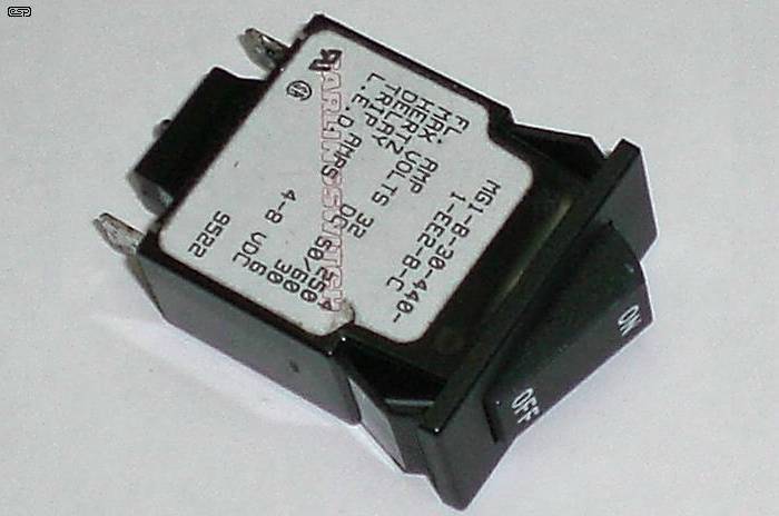
In repeated tests, the device was found to pass a maximum continuous current of about 4.25A before tripping. For instantaneous currents above 4.25A, the trip time was effectively instantaneous.
A disassembled 2.5A device is shown in Figure 3, but the 0.5A device is essentially identical. When the thermal element overheats a bimetallic strip, the strip curves back and a forked spring releases the trip plate. Pressure from the coil spring opens the circuit. The 500mA device had a rather high cold resistance of 3.4Ω, rising to over 8Ω when the element-side terminal was briefly heated with a soldering iron. The device will shave at least 2V off the protected supply at the rated 500mA current, and is therefore unsuited to many low-voltage applications.
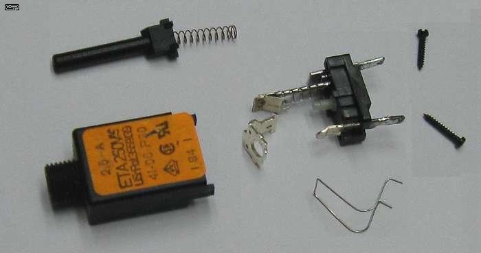
At 0.75A, or 150% of nominal, the breaker required about one minute to release. At 1A, or 200% of nominal, the breaker required 14 seconds to release. The unit required 1-2 seconds to release at 4A, and was still delayed by nearly one second at 5.5A, more than ten times the nominal current rating. While this behavior is not typical for all thermal circuit breakers, the observed results reflect the danger of relying on devices with unknown specifications if precise results are required.
The device shown in Figure 4 is a physical replacement for a 3AG style, panel-mount fuse holder. Unlike the previous thermal device, this unit specifies a maximum normal operation resistance of 0.069Ω, which was experimentally confirmed with a high-precision Agilent benchtop meter. It will not meaningfully attenuate the supply voltage anywhere within its nominal current range.
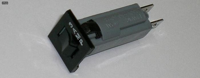
At 3.75A, or 125% of nominal, the device produced a range of clearing times ranging from as low as 82 seconds to as high as 122, with an average of 101 seconds. Increasing the current slightly to 4A (133%) produced more reliable tripping, as the average time dropped to 51 seconds with reduced spread. At 4.5A (150%) and 5.25A (175%), the respective average clearing times reduced to 17 seconds and nine seconds, and at 6.0A (200%) a consistent five second clearing was obtained.
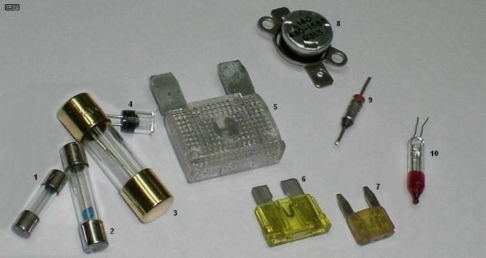
Figure 5 - A Selection of Various Circuit Protection Devices
Pictured above are (numbered sequentially and from left to right) cartridge fuses ... (1) M205 (20 x 5mm), (2) 3AG, (3) 5AG, and (4) a specialty PCB mount unit. There are also plastic (automotive) blade fuses: (5) Maxi, (6) ATO and (7) Mini. We can also see (8) a self-resetting thermal switch, (9) live-body thermal fuse, and (10) a blinking decorative (e.g. Christmas) lamp that uses a self-resetting bimetallic switch - not a circuit protection device, but using an almost identical mechanism.
Multiple fuse types and ratings were checked for consistency, but two 3AG style models with a 3A rating were subjected to extended testing: CQ-ADL, rated for time delay applications, and CQ-AFE, designed for fast acting operation. Units were tested at continuous currents of 3.75, 4.00, 4.50, 5.25, and 6.00A. Four new, unused units of each type were tested at each current level (40 units total) and the results were averaged.
At 3.75A, no failure could be achieved in either fuse type, even when the test was extended out to 20 minutes. The fuse element deformed and the current dropped slightly, suggesting significant heating in the element, but the current finally stabilised and a steady-state condition was achieved. A nuisance failure would eventually occur after repeated cyclings but the circuit would not be protected under these conditions.
At 4.00A, type ADL required anywhere from 7-13 minutes to fail, and type AFE failed in a bit less than five and a half minutes. A real-world circuit would eventually be disconnected but no portion of the attached device would be reliably protected from damage.
At 4.50A, clearing times dropped dramatically for both fuses, to 01:43 (ADL) and 00:30 (AFE). A power transformer with reasonable thermal capacitance would be protected by either fuse, although a sensitive small-signal circuit feeding from the transformer would be damaged. At 5.25A, clearing times reduced further to 50 seconds (ADL) and 6.3 seconds (AFE), and 6.00A produced 16.75 seconds (ADL) and 0.5 seconds (AFE). The circuit is now protected to the greatest extent practical.
The results can be estimated graphically as a TCC, although note that the scales in Figure 6 and Figure 7 are not logarithmic:
Slow-blow (or time delay) fuses are generally less predictable than fast blow types, and there are also different manufacturing techniques. It is impractical to try to test all types, because many suppliers consider the different types to be interchangeable, so obtaining a reliable supply of a specific type is unlikely. The general trends shown will still apply though. Also, expect to see minor differences between 3AG types as tested, and M205 (20mm x 5mm) types.
The test results demonstrate that a device can only be reliably protected when the available fault current is at least twice the nominal fuse rating.
How should a breaker or fuse be specified? The traditional approach is to use an available device rated at the nominal full load current, and then hope for the best. Some guesswork is unavoidable, but there are at least two ways to improve the odds. First, a safety factor of 2.0 is required, so the attached device must be able to sink a fault current of at least twice the nominal device rating in order to guarantee a clean trip. Anything that limits the maximum current into a short circuit must be considered carefully. For example, if the supply is 24V, and the circuit has a 10Ω source resistor in series with the power supply, a perfect short circuit on the low side of the resistor is limited to:
I = V / R = 24 / 10 = 2.4A
Accounting for the 2.0 safety factor, the fuse cannot be rated higher than the nearest size to 1.2A (possibly 1.25A, but typically 1A or 1.5A). Over-spec the fuse, and it will be nothing more than another section of wire in the feeder circuit.
Second, many hobby projects involve a transformer, and no transformer can supply unlimited fault current. If the transformer short circuit impedance can be determined, it can be used to calculate the maximum primary current that will ever flow during a secondary short. Transformer design is beyond the article scope, but we do need to know something about the short circuit test.
First, the transformer to be tested should be rated at least 20-25VA or so. Very small transformers tend to have high nominal impedances under normal operating conditions and will overheat and burn under a fault condition without tripping a conventional fuse. Where practical, the transformer should be fitted with a thermal fuse (as is done in 'wall wart' plug packs), but in some cases the designer may have to accept a transformer burnout as the normal failure mode. In such case, the fuse should be specified to protect the rest of the system without nuisance failures from supply inrush, and the transformer core should be completely isolated from the chassis, else adequately grounded where possible. Core grounding is a normal practice for all EI 'frame' transformers, but is disregarded in double-insulated equipment and cannot readily be achieved with toroids. The average hobbyist will find it difficult (and possibly illegal under local electrical safety laws) to construct DIY double-insulated equipment and is advised not to try unless using a self-protected plug pack, or equivalent low-voltage power supply with an insulated, protected output.
Second, a variable autotransformer and two digital multimeters are needed. See Figure 7. The transformer's nominal voltage ratings and the nominal power rating must be known in advance. The full load current, IFL, can be calculated for either set of windings by dividing the power rating by the nominal winding voltage. For example, if the transformer has a single 120V nominal primary and a 300VA power rating, the full load current through the primary is:
IFL = VA / V = 300 / 120 = 2.5A ... or ...
IFL = 300 / 230 = 1.3A
The short-circuit test can be run on either set of windings. For our purposes here, the primary will be connected to the variable autotransformer, with one multimeter connected as a series ammeter, and the other multimeter measuring the applied voltage. The secondaries are shorted. Small control voltage windings will contribute little to the test results, and could overheat during the test routine from normal error variations. These may be left floating, but all power windings must be involved for the test results to be accurate.
Although not used for the tests shown below, the safety isolation transformer should be considered essential. This is a normal transformer, with a secondary current capability of at least double the expected maximum test current. The primary should be rated for the mains voltage where you live, typically either 120V or 230V.
The autotransformer should be set at 0V, and power is then switched on. The voltmeter should confirm less than 1V across the transformer and the ammeter should not be measuring appreciable current. If this is not the case, STOP THE TEST NOW and check all equipment settings and connections! Otherwise, the autotransformer output voltage is slowly raised until the ammeter reports that the transformer primary's full-load current is flowing. Although it is not being measured, the corresponding full-load current will also be flowing through the shorted secondary windings. The short-circuit voltage can now be read from the voltmeter.
Note that it is not strictly required that the test current be equal to the nominal full load current. I ran some tests, and found that even a ±50% error in the test current changes very little. The final result is still quite accurate, provided both voltage and current are recorded accurately. It's also worth pointing out that should the transformer normally run hot in the (proposed) application, the test should be run at or near the normal operating temperature. Because copper has a positive temperature coefficient of resistance, the winding resistance will increase if the transformer is hot. For some smaller transformers especially, this may be sufficient to make a marginal fuse rating completely useless.
To determine the short circuit impedance, simply divide the short circuit voltage by the full-load current. For our 300VA transformer, if the applied voltage in the short-circuit test was 10V on the 120V winding when 2.5A were flowing, then the short circuit impedance would be:
RSC = VSC / IFL = (5 / 2.5 ) = 8Ω
The result is sometimes designated by Z rather than R since the impedance contains both resistive and reactive components. For simple current calculations, it can be understood and used like R in Ohm's Law.
A sample of test results for several real transformers follows in Table 3.
| Manufacturer | Model | Pri-1 (V) | Pri-2 (V) | Sec-1 (V) | Sec-2 (V) | VA | IFL (A) | VSC (V) | RSC (Ω) |
| Antek, Inc. | AN-0212 | 115 | 115 | 12 | 12 | 20 | 0.1739 | 9.84 | 56.6 |
| Antek, Inc. | AN-0512 | 115 | 115 | 12 | 12 | 50 | 0.4348 | 10.70 | 24.6 |
| Antek, Inc. | AN-1225 | 115 | 115 | 25 | 25 | 100 | 0.8696 | 8.77 | 10.1 |
| Amveco Mag. | AA-28263 | 120 | - | 57 | CT | 288 | 2.4000 | 7.29 | 3.03 |
| Amveco Mag. | AA-28263 | 120 | - | 57 | CT | 288 | 2.4000 | 7.33 | 3.05 |
| ILP Mfg. | 49783R1-1014 | 120 | - | 24 | 24 | 160 | 1.3333 | 9.71 | 7.28 |
| Toroid of MD | 4230 | 115 | 115 | 18 | 18 | 100 | 0.8696 | 5.85 | 6.72 |
| Australian Tests - Full load current shown is test current - may differ slightly from rated full load current | |||||||||
| Altronics (Toroid) | M5518 | 240 | - | 18 | 18 | 300 | 1.23 | 12.30 | 10.0 |
| Altronics (Toroid) | M5525 | 240 | - | 25 | 25 | 300 | 1.215 | 13.49 | 11.1 |
| Harbuch (Toroid) | 12417 | 240 | - | 48 | 48 | 500 | 2.15 | 9.71 | 4.5 |
| CSE (E-I) | 96501105 | 110 | 110 | 28 | 28 | 200 | 0.909 | 19.80 | 21.8 |
| Custom (E-I) | N/A | 240 | - | 28 | 28 | 300 | 1.24 | 16.61 | 13.4 |
| Unknown (E-I) * | N/A | 120 | 120 | 12 | 12 | 4 | 17.0m | 22.1 | 1300 |
* 4VA transformer included for comparative purposes only.
We can now calculate the maximum current that can flow through the transformer primary when a short circuit occurs on the secondary by simply dividing the nominal primary voltage by the short circuit impedance. Consider the 50VA transformer from the table above. The nominal primary voltage is 115V and the short circuit impedance is 24.6Ω:
ISC = V / RSC = 115 / 24.6 = 4.7A
Even if both secondary leads are screwed down to a heavy bus bar while the transformer is energised, not more than about 4.7A will ever flow in the primary even while the transformer begins smoking! The transformer will be operating at about 540VA under these conditions. Comparing the experimental fuse data obtained earlier, we deduce that any transformer fuse rated higher than about 3A fast-acting or 2A slow-blow will not reliably protect this transformer from a fault condition occurring on the secondary side.
For a 230V transformer of similar ratings, we would expect that the full load and short-circuit currents will be roughly half those measured on the 115V transformer. As a result, the required fuse rating will also be about half that required to protect the unit described above.
If we examine the comparison between the Amveco 288VA transformers and the Altronics 300VA (these are as close as we can get with the available samples). The full load and short circuit currents are as follows ...
IFL = 2.40A, ISC = V / RSC = 115 / 3.03 = 37.9A (Amveco)
IFL = 1.25A, ISC = V / RSC = 240 / 10.0 = 24.0A (Altronics)
This simple comparison shows that there is a very wide margin with these more powerful transformers, and the required fuse is about half for 240V (compared with 115V) as expected. Note that from these data, it is obvious than low power transformers are by far the hardest to protect. In many cases, an embedded one-time thermal fuse is the only safe way to protect transformers below about 10VA.
Look at the 20VA transformer in the table. Short circuit current is just over 2A, and full load current is ~170mA. This ideally requires a 200mA fuse, although a more readily available 500mA fuse will work. While the transformer is protected against a major fault, there is little protection against a sustained minor overload. The Australian 500VA transformer has a huge primary current variation, and it can cheerfully blow almost any fuse you use in the case of a serious fault (S.C current is over 50A at 240V!).
As the transformer size goes down, so does the ratio of full load to fault current - for example, some ~2VA transformers may show a significant current increase with a shorted secondary, but the current is still so small that using a conventional fuse may not be possible. Protection against small but sustained overloads is zero, because of the tiny increase in primary current. See the conclusion for more on this topic, as there is more involved than may initially be apparent.
Fuses and circuit breakers should not be selected haphazardly. Each unique type has different functional characteristics, and that protective device may be the only thing standing between the user and a fire or serious electrical shock! If a safety factor is applied to a device's trip rating, and it is properly understood that a transformer can sink only a limited amount of current in a worst-case fault, then it should be possible to design a project for a plausible fuse or circuit breaker, rather than merely hoping that the most convenient thing off the shelf will suffice.
Fusing and equivalent protection devices have often been an uncertain field for many hobbyists. Although it is not possible to completely cover the topic in a short article, the reader has hopefully been provided with enough information to improve his or her understanding of the topic, and will be equipped to build safer, more reliable projects.
Be warned and beware of small transformers (typically anything less than perhaps 10-15VA, lower ratings are progressively worse). Because these normally run with a partially saturated core, the calculated full load current cannot be used - it must be measured at full rated voltage. Likewise, the short circuit current must also be measured with the full mains voltage applied. While this will seriously overload the transformer, if tests are kept brief (as long as it takes to get an accurate measurement), the transformer will not be damaged. Make sure you allow time for it to cool to normal quiescent temperature between tests.
Everything becomes more complex with small transformers, because of core saturation. They are manufactured like that because the regulation would be woeful otherwise, due to the high winding resistance (about 550 Ohms for the 4VA unit tested). So, while the calculated full load current of the 4VA transformer is 16.6mA, with 230V applied, the transformer draws 51mA with no load, 56mA at full load, and 190mA with the secondary shorted - when you consider that you need a ratio of at least 2:1 for reliable fusing within a sensible time frame, this transformer cannot be protected reliably with available fuses, and any fuse will be somewhere between dubious and worthless.
This is made a lot worse because the copper wire has a positive temperature coefficient, and the resistance increases as the transformer get hot. Eventually, a point of thermal equilibrium would seem likely, but it will be at a temperature above the allowable maximum for the insulation. During testing, the current could be seen falling as the fault was maintained (I did a heat test for 1 minute). By the time I switched off the power, primary current was already down to ~150mA and still falling. At that stage, the transformer could only be considered warm - it was not hot (at least not on the outside - I couldn't measure the winding resistance but it can be calculated as being around 90°C based on the resistance increase).
After perhaps 5 minutes or so, one can expect that the current would fall to less than 100mA as the copper heats up more and its resistance increases. By this time, the transformer would be dangerously hot. The chances of any readily available fuse being able to protect this transformer are virtually nil - even for a dead short on the secondary. Protection against a minor overload is impossible, because the increase in primary current is so small between no load and full load. Smaller transformers show even smaller variations, hence the common application of a one-time thermal fuse buried in the windings. In many applications, the thermal fuse is the only way the transformer can be protected from a catastrophic (and potentially lethal) failure.
Large (500VA or more) toroidal transformers pose an additional challenge. While the full load current may only be a few amps, the inrush current (that current that flows when power is applied) is often limited only by the DC resistance of the primary winding. This can make the fuse selection very difficult, since it must withstand a current of 50A or more for one mains cycle, yet protect the equipment against a sustained overload - not necessarily a short circuit on the secondary. Slow-blow (time delay) fuses are one solution, the other is to use a soft-start circuit that limits the peak current to something that a fuse can handle without fatigue. See Project 39 for an example.
Ultimately, the user must realise that all forms of in-line protection are a compromise. Both fuses and circuit breakers can protect against catastrophic failure if properly selected, but it is extremely difficult to provide adequate protection against a sustained overload, particularly with audio power amplifiers. It is very common that the power transformer will be (sometimes severely) overloaded when both channels of an amplifier are driven to full power. This is not normally a problem, because in normal use the maximum power is only needed for transients, so the overload is brief. However, the fuse must not blow during normal use, but if the amp is driven to clipping and kept there for some time, the transformer will overheat. Whether it is damaged or not depends on just how hot it gets and the design of the transformer itself. Generally, this is information that often arrives too late - especially with DIY equipment. Many people have said that the ESP designs are very conservative, and this is entirely deliberate. By suggesting a transformer that is larger than really needed means that the chances of a sustained overload will not cause the transformer to fail, and makes it a lot easier to apply proper fusing.
As Aaron points out, selection of protective devices is not as simple as it may seem. Any fuse or circuit breaker should be selected based on either the transformer manufacturer's recommendations, or after some basic tests to determine the limits. In general, transformers between 75VA and 300VA are reasonably easy to protect, both against a catastrophic failure or sustained overload, although even these can be affected by significant power-on inrush current (~150VA and above). A slow blow fuse of the appropriate rating usually offers the best protection at the lowest cost. The issue of 115V vs. 230V does add an extra layer of complication though, so make sure that you understand the facts before you decide on a particular fuse value.
You can't measure the temperature directly because the primary winding is inaccessible. Because the primary is almost always wound first, it's buried to the point where you usually can't get to it. However, we can easily use the tempco of copper and a bit of maths to work it out, just by measuring the cold and hot resistance. The result will always be approximate, because we don't know how the copper wire has been processed (so its tempco can be somewhat variable). I have adopted a figure of 4 × 10⁻³.
There are some discrepancies as to the actual coefficient of resistance for copper - figures found on the Net range from 3.9E-3 to 4.3E-3. I have adopted a middle ground, settling on 4E-3 (4 × 10⁻³). Feel free to use the value with which you are most comfortable. Note also that the coefficient of resistance does change depending on whether the copper is hard drawn or annealed.
If we accept that copper has a thermal coefficient of resistance of 4 × 10⁻³ per °C, therefore, if a transformer has a DC resistance of (say) 50 ohms at 25°C, at 150°C this will increase to ...
RT2 = RT1 × ( 1 + α × ( T2 - T1 ))
where T1 is the initial (ambient ¹) temperature, T2 is the final temperature, and α is the thermal coefficient of resistance. Substituting our values in the above equation we get ...
R150 = R25 × (1 + 4 × 10⁻³ × ( 150 - 25 )) = 75 Ω
¹ Note that 'ambient temperature' is the temperature immediately adjacent to the device. It is not the temperature in the room, outside, or in Outer Mongolia!
Conversely, if we know the change in resistance, then it's an easy matter to calculate the final temperature (T2), provided we have a reference resistance taken at a known temperature before the test (T1, 50 ohms).
ΔT = ΔR / ( RT1 × α )
Where ΔT is the temperature rise and ΔR is the change in resistance. For the previous example the change in resistance is 25 ohms (75Ω - 50Ω), so we get ...
ΔT = 25 / ( 50 × 4 × 10-3 ) = 125°C
T2 = ΔT + T1 = 125 + 25 = 150°C
The only way to determine just how long it will take for a transformer winding to reach any given temperature is by measurement. Although it is (theoretically) possible to calculate it, this would require far more information than you will be able to obtain from the maker, and far more maths than I am prepared to research and pass on.
I expect that few people will ever bother to take measurements and run calculations as shown here. That's a pity, because there is so much to learn that while it may not be immediately necessary, it is useful, and increases overall understanding and general knowledge.
It's not uncommon that fuses are installed in the speaker outputs of some amplifiers (I never include them in this position), and they are sometimes also used in speaker boxes as part of the crossover network - usually to protect the tweeter. In short, this isn't a good idea, because the constantly varying temperature (and therefore fuse resistance) can actually cause distortion! Because it's almost always external to the feedback loop of a power amplifier, the distortion is uncompensated, and while it's usually inaudible, it is there nonetheless. Beware of 'Audiophool' fuses at insane prices that claim to 'fix' the problem, because they don't and can't. Fuses in an amplifier's supply lines (or in the transformer's primary circuit) do not cause this problem, regardless of claims by charlatans. Amplifiers (and preamplifiers) are mostly unaffected by small changes in the supply voltage, as evidenced by the fact that power supply ripple (which is present in almost all power amp supplies) doesn't get through to the output.
There is an 'industry' of fraudulent 'products' that never ceases to amaze (and annoy) technical writers and those who actually understand the physics behind electronic products. Amongst these are the 'audiophile' (or audiophool) fuses, which not only claim to prevent the issues above, but in some cases are even 'directional', even though no diode is used. The prices charged can be astonishing, as are the claims made by the sellers and their 'satisfied customers'. This is fraud, and the fuses (like most of the other nonsense these mongrels sell) will (and can) never do anything like the sellers claim. A fuse relies on the material heating as current increases, so it must (by definition) have resistance. While there are various materials with a well defined (and low) temperature coefficient, most have extraordinarily high melting temperatures. These alloys are used in high power resistors, but they are not suitable for fuses because they have a low thermal coefficient of resistance. Anyone silly enough to pay US$150 each for 'quantum' (quantum my arse!) fuses is not thinking clearly, or is simply hoodwinked by people who should be evicted from this planet! And yes, you can pay even more - anyone for fuses with bees wax and 'special noise reducing powder' for just US$225 apiece?
In the lands of snake-oil, there are many claims made, zero real science (unless you consider voodoo to be 'science') and no reason to buy anything other than 'ordinary' fuses from reputable manufacturers. Using fuses in speaker lines is generally unwise, but it would be equally unwise to bypass them if fitted, because that may place your speakers at risk. A better proposition is to use a DC protection circuit (such as that described in Project 33), but this isn't always possible in a commercial product. There's no reason that it can't be built as an 'outboard' unit I suppose, but that would make it a rather 'interesting' add-on.
Of course, if you happen to believe the nonsense from the snake-oil vendors you'll completely ignore everything that's been written in this article. Because the 'special' fuses you buy are (allegedly) from small workshops with mermaids as the workforce, you can be fairly sure that they won't have any test data, nor will they have any certification from UL, CSA, IEC or any other standards organisation. This could leave you in an untenable position with an insurer if your equipment catches on fire and burns down the house, but this is presumably a minor annoyance that's overridden by the vast improvement that you imagine you hear.
In general, avoid on-line 'reviews' and opinions. Few are based on any science whatsoever, and most are wishful thinking. Audio fraud is one of those things that seems impossible to stop, either because the authorities aren't interested in 'small players' or no-one has complained loudly enough. It's a sad fact that many victims of fraud never report it because they think it may make them look stupid 
High voltage fuses are different from 'conventional' fuses, in that they must be able to quench the arc that develops under fault conditions. This isn't something that most hobbyists will need, but when you're dealing with several thousand volts, the vaporised metal that forms on the inside of the fuse housing can become a conductive path. High voltage fuses almost invariably use a ceramic tube, which is filled with ceramic powder. The fuse itself must be long enough to ensure that creepage (distance along the body of the fuse) and clearance (distance through air between conductive parts) distances are maintained to suit the voltage. HRC (high rupture capacity) fuses are common for high voltage protection, and the cartridge is filled with fine silica sand, or other medium suitable for quenching the arc.
This isn't something that most hobbyists will ever need, but if you happen to be playing with valve (vacuum tube) amplifiers, you may find that a 'normal' 250V glass fuse is inadequate, and you'll need to use a fuse that is specifically rated for high voltage operation. This becomes more important if the fuse is in the DC supply, because DC can maintain an arc far more effectively than AC, which by definition passes through zero twice each full cycle.
There are no specific references, but various datasheets from reputable fuse manufacturers were used to verify some of the data. In particular, Littelfuse and RS Components datasheets were the source of some of the tabulated results shown in the Foreword to this article. Provided you avoid the charlatans there's a lot of good information to be found, but the test results that Aaron showed are his own work and don't rely on published data.
| Main Index
Articles Index
|