
|
| Elliott Sound Products | Current Detection and Measurement |
 Main IndexArticles Index
 There are countless requirements for monitoring current. The electricity meter in your fuse-box measures power, and determines the power from the voltage and current consumed. With reactive loads, the phase angle between voltage and current is used to ensure that the meter records power, and not volt-amps (VA). This also works with non-linear loads, such as the switchmode power supplies (SMPS) used for many home appliances, including high efficiency lighting (mostly LEDs these days), PC, TV and other similar devices, etc.
Being able to monitor the current is a requirement for a great many systems, and many SMPS circuits include a current monitoring function to protect the supply against overloads or short circuits. What was once a fairly esoteric area, current monitoring is now mainstream, with a wide variety of different systems used, depending on the application. While it would be 'nice' to include every possibility, that's no longer possible, because there are so many.
The purpose of this article is to give an overview of techniques, some of which are intended for low frequencies (50-60Hz) with others designed to monitor the instantaneous current through a switching MOSFET at 50-500kHz. There are requirements to be able to monitor/ measure both AC and DC (including pulsed DC), with the distinction being that DC is unipolar (of one polarity) while AC is bipolar (positive and negative).
There are two classes of current detection. One (and the most common) is a linear monitor that provides an output that is directly proportional to the current. These are used for measurement, overload detection and electronic fuses. They are also used in ELCBs (earth leakage circuit breakers, aka GFCI [ground fault current interrupters] or 'safety switches'). These have a proportional output, but the circuitry is only interested if the current exceeds a preset threshold for a preset time limit.
The second class is simply detection. These systems are used to detect that current is flowing, without being used for measurement. Some allow calibration, so only a current above the threshold provides an output. While less common for most electronic products, they are still useful. One common application is to detect that an appliance is drawing current, and turn on something else. An example is shown in Current Sensing Slave Power Switch, which can be used anywhere you need to switch on multiple devices when the 'master' device is turned on.
 | WARNING: Several circuits described here are directly connected to household mains voltages, and must be built with extreme care to ensure the safety of you and your loved ones. Do not experiment with anything that you do not understand perfectly, and can construct in a safe manner. All mains wiring must be segregated from low voltage wiring, and in many countries, mains wiring must be performed only by suitably qualified persons. | |
Whether you need simple on/ off detection or measurement depends on the circuit and its purpose. While a measurement system can be used with preset thresholds to provide a go/ no-go function, the converse is not true. Detectors are not designed to provide a linear output, and react only to current flow above a predetermined minimum. Once that's exceeded, the value of current is irrelevant. Regardless of the technique used, it's up to the designer to work out what's needed for the application.
Some of the earliest systems in industry used current transformers, which are AC only devices. Early DC measurements relied on a shunt resistor, a (sometimes very) low value, allowing the current to be displayed using a moving coil meter. Digital meters have now taken over, but with an analogue system it's often easier to see trends (current rising or falling). A shunt is calculated using Ohm's law, but because it's a series resistance it dissipates power. For example, if one uses a 'standard' 200mV digital display to measure up to 2A, there will be up to 200mV across the shunt. It will dissipate 400mW at maximum current (and the powered circuit gets 200mV less than the applied voltage). One can measure up to 2,000A just as easily, but the shunt will then dissipate 400W. Current shunts work equally well with AC and DC, but are mainly restricted to DC because there are better methods that can be used for AC.
The use of shunts is covered in some detail in the article Meters, Multipliers & Shunts. This mainly covers simple measurement systems, and other techniques aren't included. The material here looks at these other methods, many of which (at least in theory) don't dissipate power. As circuitry becomes more compact, eliminating as many heat sources as possible becomes very important, so the use of shunts isn't as common as it would have been without better monitoring methods. There are several specialised ICs available now that allow the use of very low-resistance shunts (e.g. 25mΩ) and amplify the small voltage produced (and in many cases shift the level as well). These are used in many products now, and make 'high-side' monitoring easier. High-side monitors measure the voltage across the shunt in the output voltage supply rail, but convert the output to a ground (or common voltage) reference.
AC is easier in most cases, because a current transformer (CT) can be used. These monitor the current flowing in a wire (or bus bar for high current installations), and produce an output current that's a direct representation of the load's current flow. The output from current transformers is current, not voltage. A 1:1,000 ratio CT outputs 1mA for each ampere flowing in the (usually single 'turn') primary. For industrial applications, a much higher output current is often used, with many of the older systems using a 5A output, suitable for 500A to 5,000A primary current.
Current transformers are designed specifically to work into a short circuit (or close to it). Smaller CTs use a 'burden' resistor in parallel with the output, to convert the output current to a voltage. For example, the 1:1,000 ratio CT described below will typically use a 100Ω burden, and will provide an output of 100mV/A. Improved performance can be obtained by reducing the burden - 10Ω provides an output of 10mV/A, which is better for high current measurements.
Hall-effect devices are also quite common in this role, but they are generally more expensive than current transformers. Most Hall-effect devices can measure both AC and DC, and a good example is the Honeywell CSLA2CD, as described in Project 139, Mains Current Monitor. A current transformer is used in the simplified version (Project 139A, Simple Mains Current Monitor. I have both, but the P139A is used most of the time as it's far more compact and it doesn't need a power supply. However, it cannot measure DC.
There are several options for monitoring/ detecting current in an AC circuit. The first is a current transformer, which up until recently was the best option. A CT provides excellent isolation, and all mains wiring through the transformer can easily be made very safe. Small voltage transformers can be used in a similar manner, but they require a shunt resistor in parallel with the secondary (which is used as the primary in this role). Both options require that the current-carrying conductor is disconnected to allow a CT to be installed, or the conductor must be cut to wire in a transformer/ shunt combination.
A lesser known version of a CT is a Rogowski coil. Unlike a 'traditional' CT, a Rogowski coil has no core, is 'open-ended' and it's designed to be flexible. Not having a core means that a Rogowski coil will not saturate, even at very high current. Being open-ended means it can be wrapped around a conductor without having to disconnect anything. With insulated (but individual) conductors, a Rogowski coil can be fitted to the conductor while the circuit is live.
The second is a Hall-effect current monitor IC, such as an ACS-712 or similar. These are available as a small PCB designed to interface with an Arduino or similar. There are several different types, with some of the more advanced units being very accurate (and expensive). Many are quite noisy because of the very high amplification needed to bring the small Hall-effect voltage up to something usable.
Next is a current shunt - a low resistance in series with the load. The voltage across the shunt is monitored, and it has a voltage proportional to the current. A 'typical' shunt may be 0.1Ω (100mΩ) that will provide a voltage of 100mV at 1A. Unfortunately, the shunt dissipates power, and with 1A it dissipates 100mW, rising to 10W at 10A (I²R). Unlike the other techniques described, there is zero isolation, so all circuitry is at mains (or other supply) potential. This option is strongly discouraged for mains, but remains very common (and popular) for DC.
Shunts have been used since forever. Despite their limitations, shunts are entirely predictable - provided the shunt material has a low resistance vs. temperature coefficient. This isn't difficult, with a number of suitable materials available. The power dissipation can be kept low by following the shunt with a high-gain amplifier, and this arrangement remains popular as it (in theory) has a frequency response from DC to daylight.
Finally, there's a diode string, with two or three diodes in series, in parallel with another equal string with reversed polarity (inverse parallel). This provides a comparatively constant output voltage regardless of the load current, so it's a detector and cannot be used for measurement. The voltage developed across the diodes can be used to activate an optocoupler or can be coupled with a small transformer. The transformer will be a mains type, typically used with the secondary across the diodes, and with the primary used for the output. This combination is a lot harder to insulate properly to prevent accidental contact.
Each method has its pros and cons. With current transformers and Hall-effect devices, the main limitation is the minimum current that can be detected/ measured accurately and reliably. The practical minimum for Hall-effect detectors is about 50mA, below which it's difficult to get enough output signal to noise ratio. The parallel diode string dissipates possibly significant power (the CT and Hall-effect devices don't), and that limits the maximum current that can be passed, above which a heatsink becomes essential. It can only be used as a detector, and is non-linear. It does have one major advantage, in that it's quite easy to detect anything from a couple of milliamps up to 2-5A without difficulty. The output is strictly 'current flowing/ current not flowing' though - the output is not proportional to the mains current drawn.
A current transformer offers very high signal to noise, and can detect a lower current than expected if the burden resistor (R1) is raised to a much higher value than normal. A 1:1,000 CT provides 1mA/A with the recommended 100Ω burden resistor (100mV/A). You might expect to get (say) 2.2V/A with a 2.2k burden resistor, but that won't happen because the core will saturate. For simple detection, we don't care if the core saturates, and we can clamp the output at around ±600mV with the base-emitter junction of a transistor and a small-signal diode. 50mA AC load current is easily detected with this arrangement. Saturation must be avoided for measurement.
Warning: Be aware that a CT used for high current must never be used without the burden, as a very high (dangerously so!) output voltage can be created. Remember that this is a current transformer, so the output impedance is theoretically infinite - it will attempt to provide the rated current into an open-circuit! Reality is not quite that bad, but for CTs used for high current (e.g. power distribution) can (and have) killed people if operated without the burden. In the 'old days', the burden was often a moving iron current meter, and a switchboard would (should) have a link to short the CT's output before the meter is disconnected (for service for example).

The maximum current depends on the CT of course, and the CT needs to be selected appropriately. With a 5A (primary) CT and a 100Ω burden, you'll probably be able to measure up to 10A without losing much accuracy. To measure lower current, simply wind more turns through the centre of the CT. Ten turns increases the sensitivity by ten (not surprisingly), so the 5A CT is now rated for 500mA. With a 100Ω burden, the output is 1V/A, so you'll get 500mV with a 500mA input current. Two current transformers I've used are the AC-1005 and the ZMCT103C, and datasheets for both are available in the references shown below.
The CT is a very safe option, because all mains wiring is isolated, and the CT provides extremely good separation between mains voltages and the rest of the circuit. The only change that's needed depends on the current drawn by your equipment. As a guide, the following table should help. I Min is the minimum current that can be reliably measured without complex circuitry (an output voltage of ~15mV at the minimum suggested current). For most applications (other than really high power), a 3-turn CT primary is probably a reasonable compromise.
| Load Max. VA | I Avg (230V) | I Avg (120V) | Primary Turns | I Min |
| 500 | 4.5 A | 9 A | 1 | 150 mA |
| 250 | 2.2 A | 4.4 A | 2 | 75 mA |
| 150 | 0.65 A | 1.25 A | 3 | 50 mA |
| 100 | 435 mA | 830 mA | 5 | 30 mA |
| 50 | 217 mA | 417 mA | 10 | 15 mA |
The above is a guide, and is based on acceptable dissipation within the CT's winding. For example, if you used 5 turns with a 10A continuous load, the output will be up to 50mA (1mA/A × 5 turns). This will result in a current transformer dissipation of 100mW, assuming a 40Ω winding. This is acceptable for the current transformer, but it may subject the following circuitry to higher current than is desirable.
The inherent nonlinearity of an open secondary CT is our friend for detection, but not for measurement. While the theoretical peak current can reach 50mA as described above, I ran tests and verified that it can provide that easily. I tested an AC-1005 CT with 50A primary current (one turn), and it happily provided the full 50mA into a 10Ω burden with good linearity. Linearity can be improved further by using an opamp transconductance amplifier, and this is covered next. You need to be careful though, because the optimum feedback resistor to set the sensitivity may be too low for the opamp to be able to drive satisfactorily. Most opamps cannot drive less than ~2k close to the supply rail voltages. You'd generally use the following circuit for very low current.
As noted above, a CT is happiest when its output is shorted, as that provides the best protection against core saturation. By using an opamp as a current-to-voltage converter (transconductance amplifier), the coil 'sees' close to a short, and the opamp converts the input current into a voltage. As shown above (using a 1k feedback resistor) the output is 1V/A. This works with both high and low current, but if you wanted to measure (say) 10A RMS, that demands ±14.14V peak from the opamp, which will be unable to swing its output that far. The higher than normal output current to supply the feedback resistor and the following circuitry will overload the opamp, and there isn't enough supply voltage, even with ±15V. You ideally need an opamp that can drive low impedances, or you could use a buffered opamp as described in Project 113 Headphone Amplifier. With that, you can reduce R1 to 100Ω, allowing you to measure 10A RMS comfortably. The output voltage is 100mV/A with a 100Ω feedback resistor, so you'll get an output of 1V RMS with 10A RMS. You can scale this up or down as required. You can get very sensitive current measurements with just the opamp and using 10k for R1. That will provide 10V/A, so even measuring below 10mA is easy.
Rogowski coils use a winding over a flexible (usually plastic or rubber) 'core', with the end of the winding returned through the middle of the core/ former. The far end is not electrically connected to the measurement end, so the coil can be wrapped around a current-carrying conductor without having to disconnect anything. Unlike a CT, operation without a burden resistor does not create a high (possibly dangerously high) voltage, but sensitivity is much lower than a CT. Because there's no magnetic core saturation is impossible, so very high current can be measured.
The winding is around a flexible 'core', which allows the coil to be opened to enclose the current-carrying conductor. Many commercial versions have a block at the end which protects the measurement leads and provides a repeatable gap when the coil has been installed. The gap size is important, and it must be consistent for repeatable measurements. Some use a fully shielded winding to minimise noise. An integrating amplifier is almost always needed, because the output current is very low.
There's a great deal of information available on-line, and a search will provide you with everything you need to know.
The Hall-effect devices can be bought quite cheaply, pre-mounted on a small PCB with a terminal block for the input, and pins for the supply and output. The ACS712 is very common, but there are also other similar devices available. They require a 5V supply, and the output must be amplified before it's useful. The output of a 5A version is 185mV/A (nominal), so at around 50mA you only get about 3.7mV output. Unfortunately, the noise output is quoted as 21mV (2kHz bandwidth), so the wanted signal is buried in the noise. The PCB can be modified to get a lower noise level, and a filter capacitor of around 1µF is called for (100Hz bandwidth). This certainly helps, but noise is still a problem.
It's possible to use a tuned filter to separate the wanted signal (at 50/ 60Hz) from the noise, but that means more parts and far greater complexity overall. This is very hard to justify for something that should be simple. The cost of the PCB is roughly the same as a current transformer, with these also available mounted on a PCB with an amplifier. There's not much point though, as the CT itself is all that's needed for most applications. Note that if you need to measure the current accurately, a tuned filter will give an erroneous reading, because it will only pass the fundamental (50 or 60Hz for mains), and harmonics will be discarded. This will change the reading, and it may not be possible to get good accuracy.
All circuitry connected to Pins 1-4 in Fig. 2.2.1 must be protected from accidental contact, as it's at mains potential. The maximum peak current is (claimed to be) 100A for the 5A version, but it's likely that the PCB traces on some boards will not be able to handle that. Be careful with these, as the isolation voltage depends on the device itself and the PCB it's mounted on. It doesn't take much contamination to bridge the isolation gap. A better solution is a Hall sensor with a 'concentrator' - essentially a toroid with a small gap to contain the sensor itself. An example is the CSLA2CD as used in Project 139.

There are two different types of Hall effect current sensors - open-loop and closed-loop. The ACS712 and CLSA2CD shown above are open-loop types, and the IC includes processing to compensate for temperature and linearity effects. While performance is quite good (at least at higher currents where noise isn't a problem), a closed-loop system is more accurate. These use feedback to cancel the flux in the core induced by the current flowing through the centre hole, and the internal circuitry is essentially a servo system, which maintains the net flux at zero.
One area where Hall effect sensors are useful is for the measurement of DC. A current transformer can only measure AC, where Hall effect devices can measure AC and DC, including AC superimposed on DC. This is a unique property that a CT cannot match, as they measure only the AC component. If DC is present, that will cause the core to saturate asymmetrically, ruining linearity and accuracy.
The output is derived from the output of the servo amplifier, which is (at least in theory) a perfect replica of the conductor current. These use a fairly high-power servo amplifier, which drives an auxiliary winding on the toroid. Pretty much by definition, the flux generated by the current in this coil is identical to the flux created by the (usually) single-turn 'primary'. Closed-loop systems avoid core saturation by maintaining net-zero flux, but they are relatively power-hungry and can have issues with stability. The latter is always an issue with servos. See Hobby Servos, ESCs And Tachometers for a discussion about how servos work. Most of the Hall effect sensors you can obtain for a sensible price are open-loop types. If you want to know more, see Closed Loop Hall Effect AC/DC Current Sensors (ChenYang Technologies GmbH & Co. KG).
Another class of current monitors use a fluxgate magnetometer as the sensor. These are comparatively complex but very sensitive devices, and there's a lot of information available for anyone who's interested. Neither of these will be covered any further here, but there's plenty of information on-line (of course). Suffice to say that there are many different ways to monitor current based solely on the magnetic field produced when current (AC or DC) flows in a conductor, but many can best be described as esoteric, and aren't particularly useful for DIY projects.
Reverse-connected power transformers can be used for monitoring current. A small (typically around 2-5VA transformer is connected with the secondary used as the primary, used to step-up the voltage developed across a low value resistor (up to 1Ω). A 230V primary, 6V secondary transformer in reverse will increase the voltage across R1 by a factor of 38.33 (at least in theory), but in reality it will be a bit less. A pot (or trimpot) is required to calibrate the output if it's used for measurement. The power dissipation of R1 must be verified, and remember that the output voltage can be very high indeed if the load being monitored draws high inrush current. Back-to-back zener diodes are suggested across the output, to protect any following circuitry against excessive voltage.

With a load current of 1A, R1 will have 470mV across it and will dissipate 470mW. The transformer steps this up to ~17V (9V for a 120V transformer), and 17V is easily adjusted to (say) 10V RMS output to indicate 1A (10V/A). This won't work with 120V mains, so a 3V transformer would be preferred. The circuit is not ideal though, because most small transformers are designed for good isolation of the primary winding, and the insulation for the secondary will not be as robust. If there's a major fault, the transformer's frame could become live, so it needs to be enclosed. Ideally you'd use an encapsulated type, but these are usually PCB mounting and may not be suitable.
Even small transformers aren't inexpensive though, and you'll typically pay far more for one than for a true current transformer. This scheme is useful if you already have a small transformer to hand and don't want to buy something else. Linearity is likely to be quite good, and it's improved with a lower value for R1. There's no need to be too fussy about the value, because the output is adjustable. This is a technique I've used, but it's not optimum. The very high sensitivity can be useful, but it's not recommended for high current because the shunt resistor will dissipate possibly significant power. The voltage across the shunt should ideally not exceed one tenth of the rated secondary voltage (600mV for a 6V transformer). This is to prevent nonlinearity caused by transformer core saturation. Any voltage can be used, so a 9V transformer is perfectly alright, but it naturally has a lower step-up than a 6V version. A 9V, 230V transformer will increase the voltage by about 25 times.
I tested a suitable candidate from my parts drawers. It has a 12.6V centre-tapped secondary, a 230/240V primary, and is rated for 150mA (1.89VA). The primary resistance is 1.07k, and 5Ω for the full secondary. With an input voltage of 105mV across a 0.22Ω resistor (a total resistance of 210mΩ) and 0.5A current, the output voltage was 1.49V RMS. There was no sign of saturation. However, you may find that there's a possibly significant phase shift when the transformer is used in voltage mode. This can be (mostly) eliminated by using it with a current output instead of voltage. See the previous section. Another problem with the reverse-connected transformer is that the winding resistance is much higher than a proper current transformer.
Like a current transformer, a reverse-connected transformer will perform at its best with the output connected to a low impedance (e.g. 100Ω). Even better is a transconductance amplifier as described for the true current transformer. This will minimise the possibility of core saturation and give improved accuracy.
Do not be tempted to use one of the tiny 'audio' transformers you can get. These are available with a ratio of around 1.3k:8Ω (12:1), but they don't have insulation suitable for mains usage. These are extremely dangerous if there's 230 or 120V between primary and secondary, and if you were to use one, expect it to fail spectacularly, taking other circuitry (and possibly you, too) with it to the grave. Yes, I am being serious.
As one of the most common techniques used, current shunts are an important component is countless applications. They are used in nearly all multimeters for current measurements (AC and DC), and in power supplies and many other test instruments. In all cases, a shunt imposes a 'burden' - the voltage dropped across the shunt, which is not available for the load. For example, if a shunt drops 100mV at rated current, this voltage is subtracted from the source voltage. This isn't an issue if the applied voltage is (say) 100V (AC or DC), but it may be an issue if the supply voltage is 1.8V as used my many processor ICs. The loss of 100mV reduces the supply to the processor to 1.7V, which is significant.
In the early days of electronics, shunts had to develop enough burden voltage to power a moving-coil meter movement. A 100μA movement may have a coil resistance of 1,000Ω, so 100mV is required for a full-scale reading. With modern electronics, the burden voltage has to be high enough so that the ADC (analogue to digital converter) can obtain an accurate reading. The principles are covered in detail in the article Meters, Multipliers and Shunts.

The above drawing shows the general principle for a purely analogue current measurement. There is no real difference for a digital system, except that the ADC will monitor the voltage across the shunt, and no significant current is drawn. There is an in-built inaccuracy when the shunt drives a meter movement, but at 0.01% it's not usually something that will cause a problem. The value and physical size of the shunt is determined by the current you need to measure. In the example shown above, to read 10A the shunt resistor will be 0.01Ω, or 0.001Ω (1mΩ) for 100A.
As the shunt's value is reduced, the way the wires enter and leave it become critical. If a poor wiring choice adds just 1mΩ to a 100A shunt's overall resistance (as 'seen' by the meter) the accuracy is only 50%, as the shunt appears to be 2mΩ. Great care is needed with all low-value shunts because it's very easy to add untended resistance. The second half of the drawing shows the optimum connections, with the meter take-off points directly to the resistance element.
A current detector can be made using the voltage drop across power diodes, which triggers an optocoupler. Regardless of the load current, the diodes will have a minimum forward voltage of at least 550mV each. The forward voltage is not a fixed value (0.65V is commonly [and often incorrectly] claimed to be 'standard'). A 100Ω resistor is used in parallel to ensure that the LED in the optocoupler is never 'floating', and it also reduces sensitivity a little. I tested the circuit thoroughly, and it will reliably detect as little as 1mA of mains current (without R1). The sensitivity can be varied by changing the value of R1, in parallel with the diodes. The default value is 100Ω, and lower values increase the detection threshold. Unfortunately, you can't use a trimpot because the power dissipation climbs rapidly at low values.
This scheme has a 'hidden' trap for the unwary, because LED current is always concerning. Optocouplers have what's referred to as a 'current transfer ratio' (CTR [ 1 ]), which is a measure of the transistor current vs. LED current. Most optocouplers (e.g. 4N28) have a fairly low CTR, which may be as little as 20%. That means that you need a fairly high LED current, which leads to gradual degradation of the LED. Achieving a sensible LED current isn't easy with a diode string, because the input voltage is low (between 1.65V and 2.1V with three diodes in series), and it's impossible to maintain the LED current at the optimal value (about 10mA) over the full operating current range.
If we are only interested in knowing whether current is flowing or not, the diode string and optocoupler might seem ideal, but power dissipation is a very real problem for high-powered appliances. If the detector is only used with a power amplifier (for example), the average dissipation will be fairly modest, but it's something that must be verified. Be aware that the diodes will dissipate power. If your monitored device draws 5A from the mains, each diode will dissipate about 3.5W. 5A is quite a lot, and for a 230V system that's over 1kVA (over 500VA at 120V). With high powered equipment you will need a heatsink for the diodes.
Note that the diodes must be rated for a surge current that's greater than that produced by the load's inrush current (see Inrush Current Mitigation for details). The continuous current rating depends on the current draw of the equipment. I suggest 10A diodes (TO-220 package). All circuitry within the box in Fig. 2.4.1 must be protected from accidental contact, as it's all at mains potential!
The INA250 is one example of a dedicated IC current monitor. It has an optimised Kelvin (4-wire) layout for the shunt resistor internally, and is available in four different sensitivities - 200mV/A, 500mV/A, 800mV/A and 2V/A. The shunt resistor is 2mΩ, so power loss is minimal, even at maximum current. They can handle up to 10A, and are said to have better than 0.03% accuracy for the shunt and amplifier. They are bi-directional, and are often used as part of a battery management system (BMS) to monitor charge and discharge current. The shunt is independent of the supply voltage, and it can be at any voltage between 0-36V (the latter being the maximum rated voltage).

This is one of many - similar devices are made by several manufacturers, with many using an external shunt. An example of the latter is the NCS199 series from OnSemi, available with a gain of x50, x100 and x200. While this reduces the package size, it also means that the circuit designer must be very careful with the tracks going to and from the shunt resistor. A seemingly small PCB track routing mistake can lead to a very large output error. Most device datasheets have clear guidelines for track routing to obtain high accuracy. Low value shunt resistors (e.g. 20mΩ) are more critical than higher values (e.g. 100mΩ).
While it might look like you could use one of these ICs for AC, that won't work. The current-carrying supply voltage must be within the range of 0-36V, so you'd need an 18V DC offset, and the voltage cannot exceed 36V peak-peak (12.7V RMS). It can be done, but there would be no point, and the final circuit would be much more complex than necessary.
There's one other class of current monitor (not current measurement) that deserves a mention. A non-contact monitor simply attaches to the outside of a mains cable, and detects 'current flowing' and 'current not flowing'. These are used to activate auxiliary equipment such as dust extractors or similar when a power tool is turned on. There is no ability to determine the magnitude of current flow, as there are too many variables. Most are limited to detection of perhaps 100mA (for a very sensitive detector), but around 500mA-1A minimum current is more common.
These tend to be rather specialised, but a project for one is in process (as of Aug 2025), and the basic principles have been tested and verified. They are generally not suitable for audio equipment, because the 'master' device will typically be a preamp, and they don't draw enough current to activate the sensor. I mention it here because it's an interesting application, and obviates the need to make any changes to the equipment or power lead. This makes it intrinsically safe, and can be fitted by people with no knowledge of electronics or electrical wiring.
A link to the project will be included here when the project is ready for publication.
All of the techniques described above are suitable for on/ off monitoring or measurement, other than the diode + optocoupler. That makes it the least usable method, as it can only detect that current is flowing, but not how much. The others are linear within their operating range, so can be used to measure the current quite accurately. For AC, the current transformer is a very hard act to follow, and while Hall-effect devices such as the ACS712 will work (and have a fairly wide bandwidth), they are also noisy, making low-current measurements difficult.
A reverse-connected mains transformer is handy if you have one lying around that saves you from having to purchase a current transformer, but they have limited bandwidth and may not show a complex waveform accurately. Their electrical safety is also of some concern, because the secondary (used as the primary) will rarely have very good insulation from the core and frame. The extra hassle of having to use a shunt resistor adds to its woes, but it's still a good option for measuring very low current. In theory, the transformer can be used as a 'true' current transformer, utilising the current from the primary rather than the voltage.
For DC, you have fewer choices. A resistive shunt is the standard method, which has been used almost forever. With a high-gain opamp, it's possible to get high sensitivity with low shunt resistance, but many other factors start to influence the design, such as opamp input voltage/ current offset, the requirement for a true Kelvin 4-wire shunt connection, and even the Seebeck (thermocouple) effect caused by dissimilar metals can affect the reading. Hall-effect current monitors are available for DC applications, but noise remains a problem at low current.
Most of the available ICs have a limited maximum voltage, typically from around 20V up to 40V or so. Because they have high gain, they are also somewhat noisy, and like all semiconductors have a limited upper frequency, which always falls with higher gain. The maximum allowable voltage can be restrictive, something that is not an issue with Hall effect ICs (these are fully isolated). Something to be aware of with Hall effect ICs is that any nearby magnets will cause errors. The Hall sensor can't differentiate between the magnetic field in the conductor, from a magnet or even the Earth's magnetic field (the latter is not considered to be an issue).
You must be aware of the claimed isolation voltage. Just because an IC claims 2,100V isolation, that doesn't mean that you can have that voltage between the sensing and output circuits. The Allegro ACS712 is rated for 354V (DC or peak AC) for equipment using basic insulation (earthed appliances), but only 184V (DC or AC peak) if used in double-insulated products. Failure to observe the allowable maxima can result in product failure, electric shock or even death, and it's not to be taken lightly.
Also, you need to know that there are two distinctly different Hall effect current measurement systems; open-loop and closed-loop. Open-loop designs rely on the Hall sensor being linear over its operating range, something that manufacturers have managed to do very successfully. A closed-loop system uses feedback to counteract the instantaneous flux in a 'concentrator' - typically a soft magnetic (usually circular) core with a slot cut out for the Hall sensor. These don't require the Hall sensor to be particularly linear, as the net output of the sensor is zero. The amount of voltage needed to counteract the load induced magnetic field becomes the output.
The current monitor/ detector circuit you select depends on the application. In some cases (e.g. test and measurement) you need high accuracy, low drift with time and temperature, and a range suitable for the task. Using a 50A current monitor to look at a few milliamps would be unwise, because you may not even be able to separate the wanted signal from the device noise. DC applications are usually comparatively easy, because you can use a shunt resistor selected for the expected current. For example, if you need to measure from 0-100mA, you can use a 100mΩ shunt, and you only 'lose' 100mV across the shunt at maximum current. This is of no consequence for a 50V supply, but it's significant if the voltage is only 3.3V. A point I've made in several articles is that electronics design is all about choosing the 'ideal compromise'.
You have to decide which things are important, and which other things are less so. If a supply voltage is unregulated, then you know that the voltage will vary over a fairly wide range as the mains voltage can change by at least ±10%, and sometimes more. The voltage also varies with load current, so aiming for a very small voltage loss across a shunt isn't sensible. With a regulated supply, you can sense the current before the regulator, so the output voltage isn't affected. Even if there's ripple voltage present, with most regulators the current remains almost identical to that in the load. You may have to make changes to the regulator design to ensure that its quiescent current isn't included in the measurement. This is dependent on the design used and your expectations for accuracy.
There's no point achieving (say) 1% accuracy if the current meter used can't resolve a 1mA current change for a 100mA output. The same applies at any current, and most of the time you'll only be interested in general trends rather than exact values. This is especially true when testing audio circuitry, because there's always a current range provided for opamps and IC power amps. Exact values aren't needed, and small errors are of little consequence.
AC imposes some additional challenges. If you're making a wattmeter, phase shift between voltage and current is very important. A wattmeter has to be able to compute power based on the voltage, current, relative phase and waveform distortion. It doesn't matter if the processing is digital (e.g. Project 172 or analogue (using an AD633 analogue multiplier) as described in Project 189. Both use a current transformer, and these have almost no phase shift when terminated with the recommended burden resistor. If used with an opamp transconductance amplifier (Fig. 2.1.2) phase shift is reduced to (close to) zero.
If you were to attempt the same thing with the Fig. 2.3.1 reverse-connected transformer you'll almost certainly be very disappointed, as there is considerable phase shift (about 16° as simulated) when the output is used in voltage mode. Using current mode reduces the phase shift to 6°, but it's there. This will cause the wattmeter to read low with most loads. So, while a transformer works as a current transducer, it has limited use if phase shift is important. Be warned that if you include a filter to remove or reduce noise, this will also cause a phase shift. The amount of phase shift is greatest when a low-pass filter frequency is close to the mains frequency.
Many switchmode power supplies (SMPS) use current sensors to detect a fault condition. The range of techniques include shunts and CTs, and while Hall-effect sensors are also usable I've not seen a circuit that employs them. The detection is always instantaneous, so if the current passes a preset maximum the circuit shuts down. Most then go into a 'hiccup' mode, and will attempt to re-start at intervals determined by the design. If the current is 'normal' the supply will operate, otherwise it will retry until disconnected from its input supply (mains or DC).
In the early days of transistor power amplifiers, some used a current trip that shut down the supply if the maximum was exceeded. Some of these presumably worked quite well, while others were a disaster. Mostly, the voltage across a low-value resistor was monitored, and if it reached a value that would trigger an SCR that would shut down the power supply. Many early amps used a (crude) regulated supply, and turning it off this way was easy to do.
The heart of a safety switch, aka RCD, ELCB or GFCI (aka GFI) is a current transformer. The basic principle is no different from any other CT, except that both 'primary' conductors pass through the centre (the 'live' and 'return' conductors). When everything is functioning as it should, the CT's output is zero, because the magnetic fields around each conductor oppose and cancel each other. Should a path to earth (ground) present itself (such as a fault or a person contacting the live cable), the core is unbalanced, and an output is produced. A neutral to earth/ ground fault can also be detected, because any current that bypasses the sense coil causes an imbalance. Most are designed to trip with an imbalance of 30mA or less, and a fault will register within one half-cycle of the mains waveform.

These were once known as 'core balance relays', because the core's flux is balanced (to zero) by equal and opposite current flow in the two conductors. The test switch deliberately unbalances the circuit with the designated fault current. This is typically 30mA, although some are more sensitive. Note that the trip coil releases the contacts, and once activated it requires a manual reset. RCDs are an example of a non-linear current monitor. The only thing of interest is whether the 'residual' (leakage) current is greater than the threshold. If it is, the trip coil is operated and the circuit is de-energised.
The construction of the CT coil varies, and while some use a toroidal core, others don't. US 'GFCI' breakers generally have a second toroid to sense a grounded neutral in the protected circuits. It uses the same principle as the main coil. Many GFCI breakers for the US/ Canada market appear to be based on the Fairchild (now OnSemi) RV4141 IC, which has the power supply, detection, delay and trip circuitry built in, but it requires an external SCR (silicon controlled rectifier, aka thyristor) to operate the trip coil. The application circuit shown is adapted from the datasheet.
The style used in the US is different from those used in Australia, the UK, Europe, etc. The term 'GFCI' is not used outside the US/ Canada (120V, 60Hz mains), but try as I might I was unable to find a representative schematic for an RCD. Most simply show a block diagram similar to that in Fig. 5.1, with no details of the circuitry. I did find a datasheet for one IC, but it doesn't appear to be common. Many of the first RCDs made available were electromechanical, with no electronics. The sense winding acted on the trip coil directly, without amplification. The mechanical parts (particularly the latching mechanism) are usually precision mouldings to ensure that the minimal current available would trip the breaker reliably.
It's notable that 'simple' RCDs such as that depicted in Fig. 5.1 are no longer permitted in Australia (and likely elsewhere as well). This is a Type-AC RCD, which detects only AC leakage. All RCDs are now expected to be Type-A (AC plus pulsating DC), Type-F (AC, pulsating DC or high-frequency AC) or Type-B (AC, high-frequency AC, pulsed DC and smoothed DC), with the latter types designed for electric vehicle chargers. The most common 'general purpose' RCD is now the Type-A.
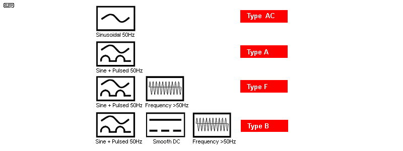
Figure 5.3 - Symbols For RCD Types
The minimum requirement in most jurisdictions is now a Type-A. Unlike basic Type-AC versions, there will almost certainly be some electronics involved to achieve anything more advanced than Type-AC. The electronics are not described here, as detailed and accurate information is difficult to find.
Not all safety switches use electronics. As unlikely as it may seem, a sensitive trip coil can be activated directly by the output of the 'core balanced' current transformer. I recently purchased a pair, and upon testing it was easy to determine that they are purely electromechanical. With an 'unbalancing' resistor of 2.2k, an input voltage of 55V AC was enough to trip the latching mechanism, with an audible 'buzz' at a slightly lower voltage before it tripped. The unbalance current was 25mA at 55V, well within the 30mA requirement. Despite the advantages obtained with an electronic circuit, they still need a fairly sensitive latch, and more parts means more to go wrong. Total reliability is expected from a safety switch, and an electromechanical system with no electronics has almost nothing to fail.
It's surprisingly easy to use a CT (I used an AC-1005) to detect a small fault current. With 27mA of 'fault' current I obtained an output of ~80mV RMS (secondary open circuit) in a bench test, and the load current is immaterial. It doesn't matter if it's 500mA or 10A, only the imbalance is detected. It's a relatively simple task to amplify that signal and use it to trip the breaker contacts. Building the mechanical parts would be a real challenge, and if you value your life I suggest that you buy an RCD from a reputable manufacturer, with all functions verified by a test lab. You can build one of course, but it has to be fail-safe. This isn't easy to achieve, and if someone were killed or injured because it failed to operate, you will almost certainly be held liable.
Note: Because of the serious risk to the health and safety of readers, I will never publish a construction circuit for a safety switch. There is a design that's been on-line for a while, but it's seriously flawed. Activation causes a pair of relays to interrupt the mains (mains load current flows via normally closed contacts), so if any part of the circuit fails, you're not protected at all. It wouldn't be so bad if the relays had to be engaged to enable current flow, but the person who designed it didn't think of that. If built properly, it would have a continuous current drain of about 50mA. The capacitor used for the transformerless power supply is an ordinary 400V DC type, not a Class-X type which is designed for mains voltages. Most constructors would be unaware of these serious errors. If you do come across it, stay well away!
Being able to monitor current has always been a requirement for electrical and electronic devices. One fairly common application is an electronic fuse ('e-fuse' - see Electronic Fuses, and of course electrical safety switches. In many cases, 'protection' is provided only by means of one or more fuses. These are still essential, because any electronic circuit can fail (including current monitors or e-fuses), and the fuse or circuit breaker is the last line of defence. In most cases, the required precision depends on the application. Some circuitry will require very accurate measurement of the current, others less so. Some don't require anything more than a preset threshold - this may (or may not) require an accurate trip-point, depending on the application.
The range of different techniques is fairly broad, with some methods more or less suited to a particular application than others. For AC, the humble current transformer remains one of the most versatile components available. Low noise and high sensitivity are easy to obtain, and they remain my preferred technique for monitoring or measuring. You can make anything from a wattmeter to an RCD using an off-the-shelf current transformer.
There's no direct equivalent to a current transformer for DC, because there's no variation in flux density, so no current is produced in the winding. Current shunts and Hall effect devices are the only choice, and these also work with AC. Although they offer good flexibility, shunts cause a power loss which is dissipated as heat in the shunt, and it reduces the voltage available to the powered circuitry. The value has to be selected carefully to obtain the required accuracy along with a low power loss, and the two can be conflicting if you want to use simple circuitry.
Hall effect devices are a good choice too, as they have almost no power loss, but have a limited dynamic range due to noise. Closed-loop designs are significantly better than open-loop for noise, but they are larger and more expensive. The final sensor choice depends on the system requirements, allowable space and budget, along with ease of calibration and overall functionality. There is no simple answer, other than "It depends ...".
Main IndexArticles Index