
|
|
| Elliott Sound Products | Hobby Servos, ESCs And Tachometers |
Copyright © 2018 - Rod Elliott (ESP)
Published January 2018
 Main Index
Articles Index
Main Index
Articles Index
Contents
Introduction
1. What Is A Servo ?
1.1 Hobby Servos
2. Motors
3. How A Servo Works
4. Servo Tester
5. Testing ESCs
6. Modify A 180° Servo For 360°
7. Build Your Own Servo
8. Proportional Integral Derivative (PID) Controllers
9. Averaging Receiver Pulses
10. Electronic Speed Control
11. Regenerative Braking
12. Tachometer Design
13. Speed & Position Monitoring
Conclusions
References
Servos are used extensively in robotics, hobby planes, boats, cars, etc., animatronics, lighting and in industry. There are countless different ways that servos are used, but in this article I concentrate on the hobby side of things - i.e. servos that are used in hobby/ robotics systems and use the standard RC (remote control) PWM control protocol. Even here there are many different types, but the industry as a whole has concentrated on a standard protocol that is used in the vast majority of applications. These servos are used with all manner of remote control (RC) systems. While these self-contained servos are the most visible to hobbyists, servo systems are used in a vast number of applications. Some include ...
This is far from an extensive list, but it gives you some idea of the diversity of servo systems. Railways (both scale models and the 'real thing') use servos to control track switches (aka points) and signal arms, as do cranes, lifts (elevators) etc., etc. Not all are electrical/ electronic - some hydraulic/ pneumatic systems can also use servos based on 'fluid logic' or a hybrid using electronic control of the hydraulic system. It's not even essential to have a mechanical output to decide if something is a servo or not. A thermostat controlling temperature is just as much a servo process as any other system listed above, and indeed this is a very common usage - even if it doesn't meet the strict definition of a servo.
Other common examples of servos are used by non-technical people, although it's not generally realised what they are. Cars are a good example. The most obvious is cruise control, which allows you to set the desired speed and the system adjusts the engine power to maintain the desired speed. Power steering is another, a comparatively small input from the driver applies an amplified version to the steering rack. Finally (of course) there's 'power assisted' brakes and ABS (antilock braking system), which use similar principles and/or feedback control. We may not think of these as servos, but they fit the definition. Early automatic transmissions used fluid logic to control hydraulic servos to perform gear changes. Servos may have rotary or linear output.
In general, a servo system is one that accepts an input, and produces an output that is in direct proportion to the original input, but often amplified by a factor ranging from tens to millions of times. Precise control is effected by means of negative feedback. The amplification can be power, distance or both. Servos are also used in 'reverse', where a large input is reduced to a very small (potentially microscopic) output, allowing finer control than a human could normally be expected to provide unassisted.
Not all servos are immediately recognisable as such because the range is so broad it covers an enormous range of different mechanisms. If you look up the definition of 'servo' the number of possibilities is huge, but for the most part you should ignore the Australian colloquialism (here in Oz, a 'servo' is also a service-station, aka an outlet that sells petrol ('gasoline')) but that has nothing to do with the topic here. 
Servos are a 'closed-loop' system, and rely on feedback from the controlled output that stops/ maintains active control when the target position has been achieved. This can be a point is space, a pressure/ force, RPM (revolutions per minute) or any other quantifiable entity. A human can be part of a servo system (in a broader sense of the term), and what is observed by the operator is corrected as necessary to achieve the desired result. Mostly, we assume that a servo has its own feedback system, but the human operator is no less a 'feedback amplifier' than an electronic circuit (but humans are usually less predictable).
In some cases, you will see the inference that stepper motors are a form of servo, but this usually is not correct because most stepper motors are commonly used 'open-loop', i.e. without feedback to confirm that the desired position has been reached. Instead, it's assumed that the stepper motor has advanced by the programmed number of steps, and this is usually very reliable unless the system is overloaded or develops a fault. Open-loop systems always need to establish their limits when the processor is started, and this can be seen with ink-jet printers for example. The back and forth operation of the print head establishes the start and end positions and verifies that there are no obstacles preventing full movement. High precision or potentially high-risk stepper motor systems may also incorporate a servo (feedback) circuit to confirm that the exact target position has been achieved.
Most quad-copters and other multi-rotor systems use multiple electronic speed controls, but have no control surfaces as such. In this case, the 'target' is a specific motor speed, and this is as easily controlled by a servo system as anything else. Rather than a position sensor, a tachometer generator can be used to verify that the desired speed has been reached and/ or maintained. Most low-cost 'drones' rely on the operator to ensure stable flight (a 'human feedback' system). Traditional servos may still be used to position cameras or release payloads on demand.

| Note: Despite the fact that this article includes schematics and circuit descriptions, this is not a series of projects. The circuits are provided by way of explanation, and although they should be functional as shown, they are not construction projects. However, they are a good start for anyone wishing to experiment, and if you are new to the world of hobby servos, you should find the info useful. The servo tester (Figure 11), demonstration servo system (Figure 12) and electronic speed control (Figure 14) have been built and tested. |
In the following, a capacitor is nearly always needed directly across the motor terminals for EMI (electromagnetic interference) suppression, but it has not been shown in the drawings for clarity. You will need to decide whether this is needed or not for your application. In some cases, the motor wires may also be fed through ferrite beads for additional EMI reduction, especially if you find that the receiver misbehaves in use. This indicates that you have an interference problem, and a complete cure may be quite hard to achieve (especially with high speed brushed motors).
The term 'servo' actually covers a very wide range of applications, but in this context, it means a motion controller as used to steer a model vehicle, operate model airplane control surfaces (ailerons, flaps, elevators and rudder) or provide limb movement for robotic systems. These are commonly known as 'hobby servos' (hereinafter known simply as 'servos'). Until comparatively recently, these servos were the mainstay of remote control enthusiasts and other modellers (e.g. model railways), but have become far more widespread as people experiment with robotics, 'battle-bots' and other mechanical systems that were once the subject of science fiction.
The earliest servo systems were commonly known as 'Synchro' or 'Selsyn' (self synchronising) motors. These were in use from the early 1900s, and were the first electrical method of remotely positioning anything from gun turrets to antennas, or sending this information from a manually activated system back to a control room for monitoring the position of the equipment. They were used extensively in aircraft instrumentation, allowing the use of wiring rather than pipework to transmit properties such as airspeed (etc., etc.). The general principle is a powered rotor, and 3-phase stator windings. The rotors were supplied from the same voltage source (115V, 400Hz for aircraft). The 3-phase stators of each are connected together (in the proper order), and movement of one rotor (the transmitter) would unbalance the 3-phase signal until the other (the receiver) was in perfect synchronisation (i.e rotational position). In many cases the transmitter and receiver were fully interchangeable, so either 'end' could be rotated and transmit its position to the other end.
There's a lot of info on-line if you know what to look for. I must admit that I've always wanted a Selsyn system, although it's more for the sake of having one than actually having a use for it. Some things are just too interesting to be ignored. Alas, my quest has not been fruitful thus far (primarily because they would constitute a very expensive toy).
Ultimately, a servo system has a control input and a feedback input. It's goal is to reduce the error between the two to zero. The difference between the the inputs represents a mathematical equation, and it is deemed solved when the error term is zero. While this sounds easy enough (opamps do exactly the same thing), it's far more complex when there are mechanical systems in play, as they have mass, friction, inertia and momentum. A good servo system relies on an understanding of control loop theory, and must consider the manifold different mechanical time constants present within the system as a whole. The task is made more difficult when the load on the controlled mechanism changes, whether due to increased friction, added mass, wind or water loads (airplanes and boats for example) or any other change - expected or unexpected.
This is not a simple task, and doubly so if a malfunction (or failure to obtain a 'true zero' result) could threaten life or limb. With the recent noise about 'autonomous' cars which require servo controls for almost every major function, this becomes all too real. Needless to say, this is not a topic that's explored here. However, the principles remain much the same, even if the 'self driving' car is equipped with artificial intelligence. The servo is a sub-system that does what it's told (well, that's the idea at least).
For so-called 'mission critical' applications, the vast majority of servo systems will be based on the Proportional Integral Derivative (PID) controller, as it can solve the 'equation' more efficiently, despite wide variations in the applied load.
Hobby servos range from miniature low-cost types with plastic gears and minimal torque through to fully metal geared models with ball bearings and big motors that can be extremely powerful. The same pulse-width control system is also commonly used for electronic speed controls (ESCs) that operate motors for wheels, propellers, helicopter rotors and even 'electric turbines' (pretend jet engines). This is a fairly crude form of PWM (pulse width modulation), but in practice it works quite well.
A fairly standard hobby servo is shown below, along with the accessories. There are four different horns, shock-mount rubber bushes, internal eyelets that fit inside the bushes so they're not compressed by the mounting screws, mounting screws and a screw to attach the selected horn to the splined output shaft. Not all servos will come with everything shown of course.
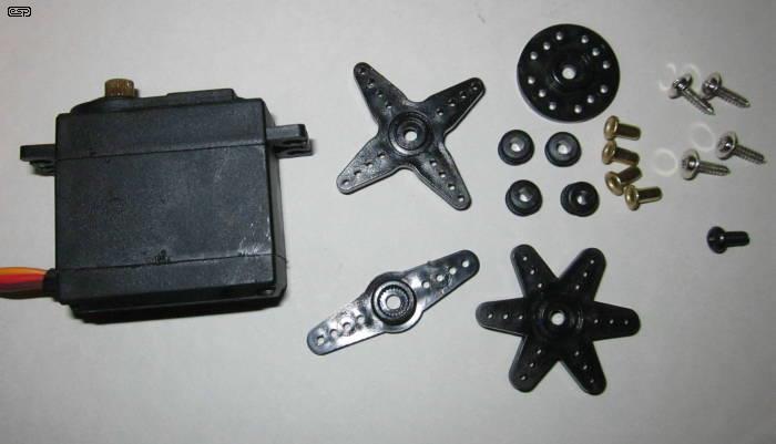
Figure 1 - Hobby Servo With Standard Accessories
Servos have used a de-facto standard PWM technique since around the 1990s to control the position of the output shaft. The pulse is fed to the servo via a control line. The control line does not supply power to the motor, this is done by a control chip inside the servo housing. There is little or no power needed for the control signal, perhaps a few microamps at most. Most servos are limited to a maximum of around 6V, although some (especially larger types) may use up to 24V. Current ranges from a few hundred milliamps up to several amps, depending on the type used and the load applied.
The motor is equipped with a gearbox (often known as a 'gearset') to increase torque and reduce the motor's speed. Small motors have high speed but very limited torque, and the gearbox is essential. Gears can be plastic (usually nylon), metal or 'Karbonite' - a reinforced plastic that has minimal wear but is much stronger than nylon. Some (at least claim to) use acetal (Polyoxymethylene, aka POM), a particularly strong, wear resistant plastic that's common in high-performance engineering components.
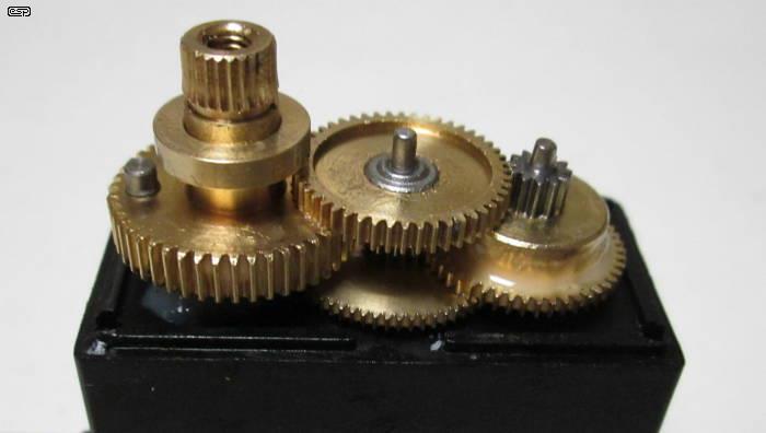
Figure 2 - Servo Gearbox (Metal Gears)
The output shaft is splined to eliminate slippage, and the shaft is fitted with an actuator, commonly known as a 'horn'. The horn can be a full disc, a two or four armed activator, or a single arm actuator so it can be matched to the requirements of the model. Most hobby servos are supplied with at least a couple of different horns, and a selection is shown above. Note the stop pin on the final output gear (far left on the largest gear wheel). If you wanted to convert this servo to continuous rotation (described further below), the pin has to be removed or cut off, or it will foul the gear that overhangs and badly damage the servo. The brass ring below the splined output is the final bearing, which can be lifted off the shaft. Just because a servo uses metal gears, that does not guarantee that heavy loads can be accommodated. The gears in the servo shown have a very basic tooth profile, not one that is optimised for minimum power loss or friction. However, the gear train is commendably free of backlash.
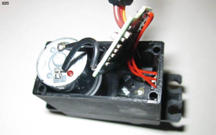
Figure 3 - Servo Motor, PCB (Removed) And Feedback Pot
A feedback potentiometer (pot) is connected to the output shaft to send position information to the servo amplifier. It's buried directly below the output shaft (you can see the three red wires from the pot to the PCB). This particular servo uses an AA51880 controller IC, with two dual MOSFET ICs (one P-Channel and one N-Channel) to drive the motor. I haven't shown the PCB as there's really nothing to see as it's all SMD parts, but if you wanted to you can get the datasheet easily and there are example circuits included. It's almost guaranteed that the circuit used in these servos is almost identical to the circuit shown in the datasheet.
The control signal for nearly all hobby servos is a very basic form of PWM, but there are a few characteristics of the signal that are fairly critical. The pulse repetition rate is usually 20ms (50Hz), but 40ms is also common. These provide a 50Hz pulse train (20ms between each pulse). The minimum pulse width is 1ms, and this equates to zero speed for an ESC, or full left (anti-clockwise) rotation of a servo. The maximum pulse width is 2ms, full speed for an ESC or full right (clockwise) rotation of a servo. The centre position (or half speed) corresponds to a pulse width of 1.5ms.
In some texts found on the Net, you may see the claim that the minimum pulse width is 0.5ms (500µs) and the maximum is 2.5ms. Other limits may also be seen (e.g. 800µs to 2,200µs) in the documentation. While some servos can accept these wider ranges, most use the 1ms-2ms protocol and some may damage themselves if the 'standard' range is exceeded. Some digital servos have a range from 900µs to 2.1ms (2,100µs), but they can be programmed to operate over the standard 1-2ms range. Many transmitters limit the travel to ±45° (or less) for many of the axes, because ±90° is far too radical for a control surface, rudder or steering system. This depends on how the model is set up of course - 90° of servo movement need not necessarily provide 90° movement of the axis being controlled.
Figure 4 - Servo Horn Positions For Varying Pulse Widths
While the drawing above shows the most common rotational directions, some servos may be different. In particular, continuous rotation types may be the opposite of that shown. These (usually) have an accessible trimpot to allow the servo to be set to stationary with a 1.5ms pulse width, which allows for some deviation from the ideal that may be encountered with some RC systems. Many remote control transmitters rely on human feedback for exact positioning of steering or flight controls, and high accuracy is not a given (especially for low-cost controllers). Some have 'trim' adjustments to allow the centre positions to be set from the transmitter. Not all servos have the full 180° range - the ones pictured above have a ±45° range when the pulse is varied from 1ms to 2ms.
There is a 'dead time' of between 18-19 (or 38-39) milliseconds between each little pulse. Some systems don't care too much about the duration of this dead time, others can be quite fussy and won't work properly if it's too long or too short (note that this is completely different from the 'dead-band' discussed elsewhere). The main purpose is (or was, later transmitters & receivers generally use different methods) to allow other channels to have their control signal transmitted - this modulation scheme is called 'time division multiplexing'. This is similar to the way multiple telephone calls are multiplexed onto a digital data stream for example, and the same requirements for synchronisation apply.
Each servo channel is assigned a 'time slot' in the transmitted signal from the radio controller (or any other system - e.g. hard-wired or infra-red light can also be used). This is the responsibility of the transmitter and receiver systems, and it is not part of the servo protocol. It will be apparent that you could (in theory) have 10 × 2ms pulses in a 20ms time period, but this would give the receiver no time to determine which pulse belongs to which channel. Most systems allow a maximum of 8 channels, but the majority of controllers have fewer - three to six channel systems are the most common.
The additional time allows the transmitter and receiver to synchronise, so the send and receive time slots are aligned. We really do want to be certain that the input signal we create for (say) channel 3 goes to channel 3 of the remote system. Without synchronisation, mayhem would ensue, with whatever one tries to control doing everything wrong. Most people would consider this to be undesirable.
Some remote controllers allow the same scheme (often (incorrectly IMO) known as PPM, or 'pulse position modulation') to be used in the model itself, so multiple servos can use a single control wire. Synchronisation is still required, but the servos must be designed for this purpose. Otherwise, a separate multiplexer is used to separate the signals into individual channels so each servo gets the appropriate commands.
Figure 5 - Internal Diagram Of A Servo
The gearing depends on the servo itself, and the final speed and torque needed. The drawing above shows a two stage reduction, but the unit pictured in Figure 3 actually has a four stage reduction gearbox. There are four pinions, but two aren't visible in the photo. The first (and smallest) is mounted on the motor shaft and drives the lowest gear in the centre of the mechanism. The drawing has been simplified for clarity.
The internals of a servo are shown in the photos above, but that only goes part way to explaining how it all works together. The control IC is obviously the 'brains' of the operation, with the motor and gearbox providing the power. The feedback pot tells the controller when the output shaft has reached the desired position, and this is provided as a DC voltage that depends on the pot's wiper position. The pot and output shaft are locked together, and ideally there will be zero backlash in the coupling.
Any backlash would result in the position being incorrect, but most hobby servos have a fairly significant dead-band (where the shaft doesn't move with small changes in the control signal). There will always be some degree of backlash in the gear train, because some clearance is essential so the gears and pinions don't bind together. There may be a significant change in the amount of backlash as a servo (or any other geared motor) wears. Proper lubrication is essential, but it's not generally mentioned in user manuals.
The electronic dead-band is unfortunate but unavoidable. Without it, the servo would oscillate around the desired set point, increasing battery drain and possibly making the control unstable in normal use. The dead-band is usually set by the controller IC, and the datasheet may (or may not) explain which resistor can be changed to reduce the dead-band to the minimum. Doing so may not even be possible, especially if the circuit is all SMD parts (which is now normal).
Some more recent designs use a digital data stream to send the information, allowing for more robust error checking and/or correction, and the repetition rate is no longer relevant. However, it's been maintained to ensure backward compatibility for analogue pulse-coded transmitters and receivers. Eventually, it's probable that these digital protocols will become dominant and servo design changed accordingly. In the meantime, there is unlikely to be any change because there are millions of products and designs using the present system.
Figure 6 - Circuit Diagram Of AA51880 Servo Controller (Typical)
The general idea of the servo driver is shown above. This is a (redrawn) example circuit provided in the AA51880 datasheet. The AA51880 IC provides the drive for the motor, and as shown it uses external N and P-Channel MOSFET transistors for the motor drive output. This is done for higher power servos - miniature types can be driven directly by the IC. By using external transistors, the allowable current is limited only by the MOSFETs and the IC is not stressed. The AA51880 allows the use of a single pair of PNP transistors, a PNP/NPN H-bridge or the MOSFET H-bridge as shown above. Device selection is based on the motor's power (and therefore its current - voltage is typically limited to 5-6V).
Figure 6A shows the circuit for the M51660 IC servo. The M51660 is a fairly old IC now, but it is (or was) very common in commercial servos. The servo-motor is driven using a full-bridge driver, so power can be applied in both directions (forward/ reverse), and dynamic braking can also be used (although it isn't provided by this particular IC). The only input is the pulse, with 1ms corresponding to full left (anti-clockwise), 2ms is full right (clockwise) and 1.5ms is the centre ('neutral') position.
The IC is analogue, but many of the latest servos are digital, either in whole or in part. Very similar analogue ICs are the M51660 and NJM2611, and while they have a different pinout, the functionality appears to be almost identical. One of the first was the NE544, which is again almost identical in terms of internal (and external) circuitry. Yet another option is the MC33030 which is somewhat similar, and is available in surface mount. However, it expects an input voltage, not a variable width pulse so external conditioning circuitry is needed for RC usage.
The 5k feedback pot is connected to the output shaft, which is geared down from the motor for increased torque and reasonably sensible operational speed. The pot is only used over about 180° of its travel (a normal pot has ~270° rotation). Many servos limit operation to ±45° for the default pulse width variation. The internal functions of the IC provide pulse-width decoding for the input signal, where the pulse width is translated into a control voltage to be compared with the output from the feedback pot. The circuit also creates a 'dead band' to prevent hunting (aka jitter). This is a condition where a servo overshoots the intended position, corrects and undershoots, ad infinitum. Digital servos generally have a smaller dead band, which improves positional accuracy. Many of the functions can be adjusted by varying the values of the external parts. For example, in the above circuit, R3 connects to the 'RDB' terminal (resistance, dead-band), which is called the 'error pulse output' in the datasheet. No details are provided as to the effect of changing the value.
Most (all?) of the latest servos use SMD (surface mount device) ICs and other parts, making them a lot smaller than the SIP (single (staggered) inline pin) arrangement used for the M51660. The operation is essentially the same though, with the electronics controlling the motor until the voltage from the position pot matches the internal voltage derived from the pulse width of the input signal. The absolute voltage of the control input is immaterial, provided it's within the range the IC can process normally. Some more recent (and more expensive) servos use digital processing which can yield some worthwhile benefits.
In this article, I do not intend to look at transmitters or receivers - only servos, but ESCs are discussed too because they use the same control protocol.
Although this article is not so much about motors, they are an integral part of servos and are also used with ESCs to provide motive power for models, so a brief discussion is worthwhile. There is a truly vast amount of info available on the Net, and there's no point adding to the repository with yet another article on the subject. However, there is more than enough here to at least get you started.
From the punk era (1979), look up "I Like 'lectric Motors" (by Patric D Martin) - it more or less sums up my own feelings on the subject.
The two main types of electric motor used for modelling are brushed DC motors and 'brushless' motors. The latter are not DC motors, even though they are commonly referred to as BLDC (brushless DC) motors. These motors are three-phase AC synchronous motors, and they require three AC waveforms, with each displaced by 120°. This creates a rotating magnetic field. The controller for these motors has to create the three phases at the right frequency, and ensure that the timing is right. If the motor slows down under load, the drive frequency must also be reduced. For modelling motors, the speed controller is commonly known as an ESC (electronic speed control).
Because these motors are synchronous (they run at the exact speed determined by the 3-phase AC input frequency), feedback is used to adjust the frequency to suit the rotation speed. The same type of motor is standard for DC fans, and a Hall-effect sensor is generally used to determine rotational speed and synchronise the electronics. They are also used in hard disk drives to spin the platter(s). These motors may also be referred to as 'EC' (electronically commutated) motors, and are becoming more common in high power applications (up to 12kW (16 HP) motors are readily available). They feature unusually high efficiency at any power level, and may eventually eliminate many traditional induction motors. However, there's a lot more to go wrong, and the ultimate in reliability is still the induction motor.
Sometimes, you may also hear these referred to as 'PMAC' (permanent magnet AC) motors. They are becoming very common for electric power of cars, bikes and boats (full sized ones). Many of the more powerful ones are liquid cooled, using a pump and radiator just like an internal combustion engine (ICE). These usually require an external controller - unlike EC motors that mostly have the controller built into the motor itself. The introduction of electric vehicles (EVs - whether fully electric or hybrid) has expanded the range of motors dramatically, but they all use the same underlying principles. EV motors are not part of this discussion.
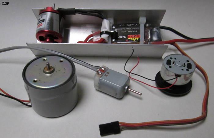
Figure 7 - A Selection Of Motors
The motors shown above are a BLDC motor with ESC (top), a speed controlled tape recorder motor (lower left), general purpose DC brushed motor (lower centre) and the platter motor from a DVD drive (lower right). The BLDC motor and its speed controller are mounted in a piece of aluminium channel so it can be used on the workbench. Because it's an 'outrunner', the rotor is on the outside and without mounting it can't be run. The cable seen with the 3-pin connector at the end (foreground centre) is the control cable, which accepts a PWM output from a model receiver.
Synchronous motors run at the exact speed determined by the AC frequency and the number of poles. For example, a four pole synchronous motor running at 50Hz spins at 1,500 RPM. Speed is determined by the following ...
RPM = ( f × 2 × 60 ) / n (Where 'f' is frequency, 'n' is number of poles and 60 is the number of seconds in one minute)
Unlike induction motors (as used in many household products such as fans, refrigerators, etc.), there can be no 'slip' (the difference between the AC frequency and the rotor (aka armature) speed). If synchronous operation is 'lost' the motor loses almost all power and stops. Many 'BLDC' motors are referred to as 'outrunners' because the rotor is outside the stator, so most of the outer part of the motor spins, with only a small area for mounting the motor at the output shaft end. The AC synchronous 'outer rotor motor' was originally made by papst GmbH and they were used for (vinyl) turntables and tape recorders, where the outer rotor acted as a substantial flywheel to provide very low vibration levels. There is little historical info on these, but I still have one in my workshop. These motors started as induction motors, and once up to speed the permanent magnets would allow the rotor to 'lock' onto the rotating magnetic field to achieve synchronous operation. Starting torque is low, and no (significant) load can be applied until synchronous speed is reached.
The functions for BLDC motors are generally provided by a fairly comprehensive micro-processor, such as those made by ATMEL (e.g. ATMega or similar) which seem to have the lion's share, but other microcontrollers can be used as well. Controllers designed for brushed DC motors are (usually) far less complex, but some of those incorporate additional functions, such as dynamic braking. The motor is shorted out (under user control) which makes it stop very quickly. Braking can be via PWM (so it's controlled) or instantaneous upon reaching the 'stop' condition - typically a 1.0ms pulse from the controller unless the controller also provides the facility to reverse the motor. Dynamic braking is uncommon with reversible motors, but it can be done with a comprehensive controller.
Brushed DC motors use permanent magnets and a commutator, a segmented contact arrangement attached to the rotor. Electrical contact is made using carbon (graphite) brushes, so the motor effectively creates its own rotating field. The brushes are arranged to ensure that as the magnetised armature pole approaches one of the magnetic poles in the stator (the fixed part of the motor), the next pole is connected by the commutator so each rotor pole can never be fully attracted to a stator pole - it's a continuing sequence of attraction and repulsion, switched by the commutator. Reverse is achieved simply by reversing the polarity of the power supply.
Most common brushed DC motors use two permanent magnets for the stator (one North, the other South magnetic pole). The rotor is almost always three poles, although some use five poles for more power and smoother operation. The commutator may have the same number of segments as the motor has poles, but sometimes there will be (perhaps many) more. DC is applied to brushes that make contact with the commutator. The brushes are usually carbon, and eventually they will wear out and for small motors, the motor usually has to be replaced. A drawing showing the essential parts is shown below.
Figure 8 - Brush Type DC Motor Components
Larger brushed motors (such as those used for mains powered drills, vacuum cleaners, etc.) are classified as AC/DC (no, not the band with the same name ), although the band did choose the name when it was seen on a sewing machine motor. They are also known as 'universal' motors, because they can use AC or DC. These do not use permanent magnets, but use separate stator windings. The stator and rotor windings are usually in series, but parallel operation is also used (as well as a combination of the two in some cases). These motors can run in reverse by reversing the connections to the stator or rotor windings (but not both). Many are optimised for their 'normal' direction and the brushes will arc excessively if they are run in reverse. The brushes are usually replaceable in these motors. Most are multi-pole, and often use two commutator sections for each pole (e.g. a 12 pole motor has a 24 segment commutator). Note that the armature current in any brushed motor is AC, even if it's operated from DC.
Series wound DC motors are also used as the starter motor for most cars, as they have extremely high stall torque, and like all series wound DC motors they can reach dangerous speeds if operated with no load. Nearly all small motors use permanent magnets and a laminated steel (aka 'iron') rotor with the windings attached, although some are 'coreless' (aka 'ironless'), meaning that they do not use a steel core. This is done where extraordinarily fast response is required, because the coreless rotor has very low mass and minimal inertia. Torque is generally lower than for a similar sized 'iron cored' rotor.
Many motors (especially BLDC types) for hobby applications are rated in K/V (also shown as KV or KV), where 'K' means unloaded RPM. You may assume from this that a 2,000K/V motor would run at 2,000 RPM with a 1V supply, 4,000 RPM with 2 volts, etc. However, this figure can only ever be taken as a guide, and probably will never be reached in practice. The common assumption is not strictly correct (look it up if you want more details), but it does give an approximate figure that may be helpful in a limited number of cases. It can be helpful to compare otherwise similar motors, but that only works if the maker's specifications are accurate. In general, a high KV motor will spin fast, but has little torque, while a lower KV rating means lower speed but higher torque.
Don't confuse K/V (or any of its derivatives) with kV which means kilo-volts (1kV is 1,000V).
One trick that may be useful ... an old hard disk drive (HDD) motor can make an excellent tacho-generator. If you use only diodes to rectify the AC output there will be some non-linearity and temperature dependence, but for most applications this won't matter that much. Greater accuracy can be obtained using precision rectifiers (see Precision Rectifiers - ESP AN001) for details. If you want/ need a high precision system, you almost certainly won't be messing around with hobby motors or servos, so this won't apply. There is no 'ideal' HDD motor for the task - some are 3-wire ('delta' or 'Δ' connection) and others are 4-wire ('star', 'wye' or 'Y' - three phases and a 'neutral' connection). Rectification is easy, but you need 6 diodes for a 3-wire connection. Only three diodes can be used for a 4-wire version, but it has a lot more output ripple. A six diode rectifier is always preferable. The common ('neutral') wire of 4-wire ('star' connected) motors can be ignored for a tacho-generator, even though the motor is wired differently internally.
You can use any DC motor as a tacho-generator, but some brushed DC motors may place an unacceptably heavy load on the drive motor. Another method to measure speed is to use a photo-interrupter with a slotted disk that passes between a LED and a photo-transistor. The disk is attached to the motor shaft, and the pulses can be integrated (after pre-processing to get equal pulse widths regardless of speed) to produce a DC voltage that's proportional to the motor's RPM. In some cases the disk is coded, so the drive system knows not only the speed, but the rotation angle at any moment in time. Whatever method you use to get a speed dependent voltage, this can be compared to the control voltage to keep the motor speed constant despite varying loads. The techniques for speed control vary, but most these days will use a micro controller rather than the analogue techniques that used to be common. Tacho-generators are available as specialised devices so you don't have to use whatever comes to hand, but hobbyists usually will use something they already have, rather than buy an expensive commercial unit.
There's another common technique used to monitor (and correct) the speed of a brushed DC motor, and that's to measure the back-EMF (back electromotive force). The motor is powered using PWM, and during the 'off' period, the motor will generate a back-EMF that's directly proportional to the motor's speed. The higher the speed, the higher the back-EMF. This can be monitored using analogue or digital techniques and used to control the motor's RPM. The circuit requires gating techniques to ensure that only the back-EMF is measured, and not the applied voltage. It's easy to do, but does add some complexity to the circuit.
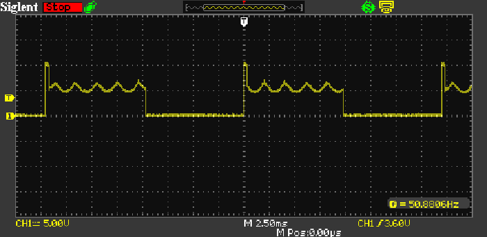
Figure 9 - Back-EMF Waveform From PWM DC Motor
The waveform from a more-or-less typical DC motor is shown above. The motor was supplied with 10V via a PWM speed controller (Project 126). As the MOSFET turns off, there is an inductive 'kick' seen on the rising edge of the waveform, equal to the supply voltage. It's only brief, lasting around 500µs. After that, the voltage seen is the motor's back-EMF (including ripple which is normal). As the motor is loaded, the back-EMF falls, and this is used to provide feedback that increases motor power to restore the preset RPM. The average back-EMF level is a little under 5V in the example shown. Note that the back-EMF voltage is measured from the positive supply in the example shown.
When the back-EMF falls, the voltage between 'power pulses' rises referred to zero volts (so falls referred to the supply voltage). If the motor is driven faster (by a vehicle going down an incline for example), the back EMF will become negative because the power supply voltage is fixed at 10V in this example. See Regenerative Braking below to see what happens when the motor is driven faster than its normal speed for a given supply voltage.
The other motor type in common use (but not for models) is the induction motor (aka 'squirrel cage' motor). These are asynchronous, and rely on 'slip' between the rotating magnetic field and the armature. This means that the rotor always runs slower than the frequency and number of poles would suggest. Slip generates a current in the armature, which generates magnetic flux that tries to maintain synchronous speed, but cannot. Without slip, there is no armature current and zero torque. A four pole induction motor at 50Hz will typically run at ~1425 RPM at full load (5% slip). There are many different types, including shaded-pole (used for fans and other very low power devices), capacitor start and 'PSC' (permanent split capacitor), 'split-phase' using a resistive start winding and centrifugal switch, the rather obscure 'repulsion' motor (several versions exist), and of course 3-phase induction motors. The latter are the work-horses of industry, and are one of the most common machines ever built. While they are interesting (at least I think so), they are not discussed further here because they are irrelevant to this topic.
For anyone interested, there's more information about motors in the article Clock Motors & How They Work. The article concentrates on motors used in clocks, but you may find it interesting as similar principles apply and there's a lot of detailed explanations.
In most cases where the output is to a wheel or other land based propulsion system, the motor will require a gearbox or some other form of speed reduction. There are few small motors that run with high torque at low speeds, so the reduction gearing increases torque and reduces speed to something more sensible. Running a 100mm diameter wheel at a leisurely 10,000 RPM would result in a speed of over 52m/s at the periphery - equivalent to 188km/h. This is clearly much too fast for most applications, so reduction gearing is essential. The same applies to propellers for boats and even many planes. The only time extreme speed is used is with small propellers as commonly used on miniature quad-copters.
Most applications require lower speeds, and the tip of the propeller/ rotor blade should not exceed the speed of sound (about 343m/s). A 30mm diameter propeller can spin at over 200k RPM before it even comes close to the speed of sound, but if increased to 300mm, the maximum is around 20k RPM (still well within the capabilities of many motors). Remember that any speed reduction system (whether gears, chains or belts) incurs some loss of power because no mechanical system can be 100% efficient. Frictional losses dominate in all cases, and can be surprisingly high. This means that the motor always needs more power than you expect at the output.
Something that seems to cause some confusion is the claimed number of turns for 'performance' motors. A 23T motor has 23 turns of wire for each pole, so draws a lower current (and spins slower) than an otherwise equivalent 13T motor. Unfortunately, it seems to be very hard to get any definitive information on this, but the occasional forum post may have some factual details. There is very little detail available, other than to point out that some motors are designed specifically for racing, and many of those are not intended to be reversible - they are specifically designed for maximum performance in the direction indicated on the motor itself. They will run in reverse, but may draw excessive current and will perform badly. The range of 'turn values' is quite broad, ranging from less than 4 turns (BLDC motors only it appears) up to 80 turns or more.
For those who like to experiment for the least possible expenditure, old battery drills are a great source for motors with (usually) a double-reduction planetary gearbox. Although many have a torque adjustment, this needs to be defeated for the motor/ gearbox to be useful. I've used these units for a few tasks in my workshop, with one used to provide motorised operation of the X-axis of my small milling machine. Another is used for a coil winder. They generally have lots of torque, and are easily adapted to the speed controller described further below, or the unit shown in Project 126. The project is just a speed controller - it doesn't accept a servo input and has no speed regulation (its original purpose was for LED dimming for lighting applications).
One other type of motor deserves a mention, although they are unlikely to be used in most models. Pancake motors get their name from the fact that they are flat discs, rather than cylinders. Many use an ironless rotor, so they have very low inductance, zero 'cogging' (the tendency of the iron poles to align with magnets). The ironless rotor and method of construction means that they can have a very fast response time due to very low inductance, and the low inductance means that brushed types suffer minimal commutator arcing. These characteristics are also shared by other ironless rotor motors. Pancake motors can be brushed or brushless, with the latter needing a similar controller to other BLDC motors. Because of the relatively large diameter rotor, pancake motors can offer improved torque compared to conventional designs. Some are made using printed circuit boards, with the windings created as PCB tracks. It's common for this type of pancake motor to use the PCB as the commutator as well as the windings, resulting in a very compact design that's (theoretically) relatively cheap to make.
A servo is an electromechanical feedback system. As already noted in the intro, there are many different types, but here we'll look at basic position control systems. The input pulse is translated into a voltage internal to the controller IC, be it analogue or digital. This voltage is compared against a feedback voltage derived from a rotary encoder - most commonly a potentiometer for hobby servos. The idea is shown below, as a purely analogue process. While it's shown with a dual supply (±12V), this is for ease of understanding. Dual supplies are rarely used for hobby motor drive systems, so polarity reversal is achieved by using an H-bridge as shown in Figure 12.
The drawing shows the essential elements. The error amplifier detects that there is a difference between the voltages from the control (VR1) and feedback (VR2) pots. Any difference is amplified and applied to the motor drive circuit. Should the output of the amplifier be positive, the motor will spin in one direction, and it will spin in reverse if the polarity is negative. This allows the motor to be driven at a variable speed in either direction. Note that the drawing does shows only the most rudimentary loop stabilisation network, namely C1. These networks can become quite complex, but are always necessary to ensure that the phase shift through the mechanical linkages does not result in an unstable system. The gain also needs to be low enough to ensure that the total electromechanical system remains stable, but high enough to ensure there is a minimal dead-band (a range where the motor has insufficient drive voltage to function).
Figure 10 - Conceptual Diagram Of A Servo
It should be apparent from the above that the error amplifier is simply a differential amplifier. When both inputs (from the 'Control' and 'Feedback' pots) are at the same voltage, the output must be zero, so the motor doesn't move. If the control pot is moved, the motor is driven in the appropriate direction as to cause the 'Feedback' pot to produce the exact same voltage as provided by the 'Control' pot. When the two are equal, the motor stops again. The gain (set by R2 and R4) can be increased to reduce the dead-band, but if set too high the servo will oscillate (called 'hunting'). There is a complex set of electrical and mechanical time constants that can make it very difficult to stabilise a high gain servo. This is made worse when it's controlling an external mechanism, because that will also affect the mechanical time constants and make a stable system unstable (or vice versa).
Mechanical systems have a direct analogue in electronics. Friction is the mechanical equivalent of resistance, 'springiness' (compliance) translates to capacitance, and mass is the equivalent of inductance. So-called 'stiction' (the tendency of some mechanical parts to need extra force to get them moving) is a form of hysteresis. A gearbox can be represented as a transformer, although this 'conversion' is rarely needed. Unfortunately, these mechanical equivalents are often next to impossible to calculate (except for the 'transformation ratio' of a gearbox), and this is made worse by the fact that they are not constant. Most servo controlled load-bearing actuators perform very differently on the workbench from how they behave in normal use. This (and the fact that 'normal use' may cover a very wide range), means that even if you do work out the electrical analogues of the mechanical variables, the data obtained are likely to be useless. Commercial servos get around these constraints by making the dead-band large enough to ensure it will not cause instability in most systems.
The general scheme of a servo doesn't care if the processing is analogue or digital, as long as it provides the same end result. The error amplifier is the heart of the system - it determines if the 'control' voltage is higher, lower or the same as the 'feedback' voltage. If the control voltage is different from the reference, the motor turns in the required direction and the gearbox drives VR2 until the voltages are the same. Each change of input (control) voltage will cause the error amp to react, and drive the motor in the required direction to restore equilibrium so the system is at rest, but with the output at a position mirroring that of the 'control' pot. Should the output shaft be forced into a different position, the servo treats that in the same way - the motor will be driven until the output position is where it should be (within the ability of the motor to overcome the load).
All of the hard work has already been done with a commercial servo or off-the-shelf servo controller IC, so the user only has to provide the control signal. Now it should be easy enough to visualise a bit of additional circuitry that converts the pulse width into a voltage, and that is used instead of the 'control' pot shown. However, the control pot is still used - it's in the transmitter, and is one of the controls provided to the operator. When the control pot is moved, the voltage is encoded, transmitted, received, decoded, and used to control the servo.
There are two main types of servos available - analogue and digital. There is no difference as to how the servo is controlled by the user, and the main difference is the way the servo motor is driven by the internal controller circuitry. Digital and analogue servos both have (usually, but not always) identical housings for a given size, and use essentially the same type of motor and gearbox. Most are interchangeable with each other (i.e. digital and analogue). Digital servos can be more responsive than their analogue counterparts, because processing power (necessary for complex feedback loop stability calculations) is now so cheap.
The difference is how the motor is controlled by the internal electronics. The motor in an analogue servo receives a signal from the servo controller at a nominal 25-50 times a second, based on the repetition rate, and this is the default refresh speed of the servo, which determines the positional accuracy and stability under load. Digital servos can achieve much higher position refresh rates depending on the code in the controller itself. By monitoring and updating the motor position more often, a digital servo can deliver full torque from the start of movement and can increase the holding power and accuracy of the servo at the selected position.
The rapid refresh rate and high processing power may also allow a digital servo to have a smaller dead-band. The response of the servo is improved, and along with the increased holding power and the rapid maximum torque delivery, digital servos can accurately set and hold the actuator position better than their analogue counterparts. This isn't to imply that the same can't be achieved with an analogue servo, but it requires more circuitry and will be more expensive to make.
Some digital servos can be programmed. This may include direction of rotation, centre and end points, fail-safe options, speed and dead-band adjustment. Programming is not always required though, as even most programmable digital servos operate like 'normal' analogue servos out of the box. Digital servos are usually more expensive than analogue types, and may require (sometimes significantly) more power from your batteries.
Another term you will see is 'servo-motor'. While this often refers to the motor inside a hobby servo, the term actually means something else in industrial systems. A servo motor is a motor with a feedback system to indicate exactly how many revolutions (or part thereof) it's done, and the motor itself may be AC or DC, brushed or brushless, and may use an 'ironless' rotor for very fast response time. The feedback system is commonly a rotary encoder which can report not only the number of revolutions done, but also the speed. Positional accuracy can be extraordinarily high, and they are common in large (and expensive) laser cutters and other industrial systems. These fall way outside the scope of 'hobby servos'.
There are several different wire colours used with hobby servos, and you should consult the maker's information to ensure that you don't apply reverse polarity. This will destroy the internal electronics, usually instantly. The colours vary from one maker to another, but it's become standard to have the red wire (positive) as the centre pin. Reversing the control and earth/ ground wires usually causes no harm, but you should always check. The maximum rated voltage must never be exceeded or damage is almost guaranteed. Most are designed for operation between 4.5V and 6V DC. The current required depends on the size of the servo and the load applied. If the load is greater than the design maximum, you can strip gears or burn out the motor and/or electronics.
If you use servos, one thing that you really need is a servo controller - a device that you can use to test servos, without having to hook them up to receivers and adjust the servo position (or motor speed) from the transmitter. There are actually quite a few designs published on the Web, but very few are particularly accurate, some will be close to unusable, and none that I've seen provide separate controls for the repetition rate (or dwell time) and the servo control pulse width.
Most servos are designed for ±90° rotation, giving a nominal 180° of angular movement. However, it's quite common that the actual rotation is less than this. Most standard servos can also be modified to allow full 360° rotation, in forward or reverse. See further down this page to see what needs to be done to achieve this. You may need to modify the servo circuitry to get a usable speed range when a standard servo is adapted for continuous rotation.
To be able to test a servo properly, we will ideally have control over the repetition rate (between pulses) and the pulse width. The circuit shown below does this using two pots, one to adjust repetition rate (VR1 is a preset) and the other to set the pulse width (VR2). The repetition rate should be set for 20ms (50Hz) and the pulse width is 1.5ms with VR1 centred, corresponding to the centre position of a servo. Alternative timings can be used for the repetition rate, but 50Hz is close to ideal. VR1 can be a front panel pot if preferred. D3 is a Schottky diode to protect the circuit against reverse polarity. D2 is a 'power on' LED of any colour you like.
Figure 11 - Circuit Diagram Of Servo Tester
U1 controls the repetition rate, and is a 'minimum component count' astable oscillator. Timings assume exact values and adjustment will be needed using VR1. The formula below assumes that the high output level is 5V, but that's usually not the case in practice. However, the repetition rate isn't especially critical and most servos will be happy enough if the timing is a little outside the optimum value. The frequency is (ideally) determined by R1 + VR1 and C1 (the resistor and trimpot are in series) ...
f = 0.72 / ( R × C ) Where f is frequency, R is resistance in ohms, and C is capacitance in Farads
The trimpot gives a fairly wide frequency range so setting 50Hz will be easy to achieve (VR1 should ideally be a multiturn trimpot). The centre frequency is set for 50Hz (20ms). The output of U1 is fed to the differentiator circuit (C4, D1 and R2). The circuit ensures that only a very narrow pulse is used to trigger the pulse generator (about 60µs wide at the 555's trigger level of 1.67V). D1 is a BAT43 or similar low current Schottky diode. and is used to ensure that the pulses from U1 don't exceed ~5.6V at pin 2 of the 555 timer. The switch is recommended to allow selection of a nominal 20ms or 40ms so you can use and/or test both rates.
U2 is a monostable, and controls the pulse width. The theoretical timing based on the values shown are 902µs minimum, 2.002ms maximum, with a centre position giving 1.45ms. This is determined by R3 + VR2 and C5 + C6, again in series and parallel respectively, and using the formula for a 555 monostable ...
t = 1.1 × R × C Where t is time
Of course, this again assumes that the cap values are exact, and that VR2 really is 10k. Mostly, they will be a little different and it may be necessary to adjust the value of C5 and/ or R3 to get the range required. Trimpots can be used, but it's unlikely that anyone needs the level of accuracy that can be achieved by making very fine adjustments. Servos are not really precision devices, and in most cases they rely on user feedback rather than absolute precision. If preferred, C4 can be 82nF and 10nF in parallel, which will give almost perfect 1-2ms.
Note that it is certainly possible to do everything with a single 555 timer, but the accuracy is nowhere near as good and it's difficult to adjust the repetition rate independently of the pulse width. Even that is possible, but some interaction is inevitable. For the cost of a second 555 timer and a few cheap parts, the circuit shown has greater flexibility and is much more easily calibrated. While simplicity is always a virtue, that's not true if the circuit ends up with needless interactions that make it harder to use. The monostable circuit is very predictable, but free-running (astable) oscillators are not as good.
The circuit is easily wired on Veroboard, but if there is sufficient demand I will make a PCB available. Nothing in the circuit is particularly critical unless you are aiming for very accurate pulse widths and/ or repetition rate. As already noted, the latter is generally not at all critical, provided it falls within the general range of 15ms up to a maximum of perhaps 60ms. If it's too long, the servo may not be able to maintain the set position and/ or it will chatter. If too short it may cause problems with the servo circuits.
The circuit should be powered from a 5V source with enough current to drive the tester and the servo(s) you need to test. The current will usually be less than 1A, but some may need more. The servo itself connects with a 3-pin connector, providing GND, +5V and Control. Most servos have the +Ve pin in the centre so that a reverse connection doesn't cause the release of the 'magic smoke'. However, you must check to make certain. While the majority of servo manufacturers have standardised the connections, some older types may be different. Wire colour codes are not standardised, with the possible exception of using red for the positive (but even that is not 100% reliable).
If you don't want to build your own (why not?), you can buy 'servo testers' for a rather paltry sum, but naturally you don't actually learn very much by using an off-the-shelf product. Yes, it's convenient and painless, but the greatest advantage of making your own tester is that you can see exactly what it does, and tweak things to suit your needs. When you buy one, you get a complete unit, no schematics, often erased IC type numbers, and you have no idea what it's doing or how to change anything.
ESCs (electronic speed controls) are usually not servos. They accept the same PWM signal, but most have no feedback mechanism, so the motor slows when loaded. To be classified as a 'true' servo system, some form of monitoring the shaft RPM is needed, with correction applied internally to ensure that the speed remains at the preset value. Given the processing power of some ESCs it would be easy to add, but in the case of models it may be preferable that additional loading does slow the motor, and it will be corrected as needed by the operator (another example of the 'human feedback' system at work).
When testing ESCs, you'll likely find that the ESC provides the 5V power, and an external supply isn't necessary. This depends on the ESC of course, as not all are exactly the same. 5V power is provided by an on-board 'BEC' (battery eliminator circuit), but you must check the manual for your ESC to find out if it has a BEC or not. Where provided, the BEC has a regulated 5V output.
ESCs come in a wide variety of different forms. Those used for brushed DC motors are completely different from those used for brushless DC motors, which are actually three-phase AC motors. The ESC generates the 3-phase output at the required speed to run the motor. The basic operation is discussed above, in the 'Motors' section.
ESCs designed for brushed DC motors are (usually) far less complex, but some of those incorporate additional functions, such as dynamic braking. The motor is shorted out (under user control) which makes it stop very quickly. Braking can be via PWM (so it's controlled) or instantaneous upon reaching the 'stop' condition (typically a 1.5ms pulse from the controller).
Some ESCs allow forward and reverse (a 1.5ms pulse stops the motor), while others do not. Again, you need to verify the facilities provided and ensure that the system is used in accordance with the instructions. Some ESCs allow programming (albeit rudimentary in some cases), and it may be far easier to do using a tester than having to mess around with transmitters and receivers. While the tester described can do basic 1-2ms pulse widths, there may be other functions in some transmitters, so the tester may not be able to do everything.
However, based on the research I did for this article, it's unlikely that there will be anything that you can't test, with the exception of a fully digital system that uses a different control protocol. I've also used the tester with a Mystery MY30A ESC and an 'outrunner' (outer rotor) motor, and it behaves perfectly in all respects.
Most standard 180° servos can be modified to obtain continuous rotation. It's usually better to get one that's designed for the purpose, but it may not always be practical. There are two changes needed, with the first one being the position pot. This must be disconnected from the output shaft, but you usually won't be able to re-use it to set the 'off' position. It's often suggested that a pair of equal value resistors be used, but it's better to use a trimpot, as that allows you to calibrate the servo for no movement with a 1.5ms pulse from the controller.
The second change is to remove the stop-pin, which limits the movement to 180°. Depending on the servo, this may be easy or difficult, but either way a rotary tool can be used to cut off the pin which is located on the main output gear. The gears should be removed from the gearbox if possible, or you'll end up with plastic or metal filings throughout the gear train. These will cause undue wear, and may even cause the gearbox to seize. If the pin is plastic, it may be possible to cut it off using side-cutters, but make sure that it cannot catch on the gearbox internal stop lugs or foul any of the remainder of the gear train.
If you can't figure out what to do from the descriptions and photos shown above, there are several on-line guides that show all the parts and mods needed for the conversion. Bear in mind that most servo motors are not rated for continuous operation at full power, so you need to use something else if you need fairly powerful continuous drive motor. You'll usually be a lot better off using a dedicated motor and gearbox assembly along with a matching ESC.
In general there's little or no need to build a servo, because they can be bought fairly cheaply and have everything you need. Sometimes, you may need a simple servo that is purely voltage controlled, along the lines of that shown in Figure 10. You could just use a DC Servo Motor Controller/ Driver IC of course, and although that removes most of the complexity it may also be hard to find. The other reason to build your own is for the sake of learning and experimenting. I designed a circuit many, many years ago that was used as an educational tool, and a similar approach ensures the minimum of complexity. This is especially true for gearing, which is hard to do without a gear cutter or a supply of mating gears, pinions, shafts and end plates.
The easy solution is to use a length of threaded rod, directly attached to the motor shaft. A nut is driven by the threaded rod, and this also drives a slide pot which is used for feedback. This gives a linear servo (aka linear actuator), and although it won't have much power with a small motor, it can use as big a motor as you're game to install. A large motor also means high current and much larger power transistors of course.
If you use a second motor driven from the first, you can use it as a tacho-generator, so you can accurately set motor speed, rather than actuator position. These are available commercially, but are often very expensive. The output of the tacho-generator is connected in place of the feedback pot. It will need to be filtered to ensure there are no high voltage spikes that will cause erratic speed control.
The conceptual circuit shown in Figure 10 is actually usable, but the requirement for a dual supply makes it awkward to use in a battery powered system. To make it workable with a single supply requires an 'H-bridge' circuit, using four transistors to control the motor current. The basic circuit is still fairly simple, but it's important to set the gain appropriately. If it's too high, the circuit will 'hunt' (oscillate around the set point), and if too low there will be an excessive dead-band. This is no different from commercial RC servo systems which are limited by the same constraints. The capacitors marked with '*' (C1 and C2) are optional - they may be needed with some systems as they depend on the characteristics of the motor and feedback system. The values shown are intended as a starting point.
Figure 12 - DIY DC Servo System
The circuit shown above is a fully built and tested servo system, and it works exactly as expected. It uses a single supply, so it's usable in most models or in conjunction with other systems that use hobby servos or ESCs. It is a great way to demonstrate how a servo works, either for yourself or others who are interested. The one I built is designed specifically for teaching purposes, in this particular case to demonstrate to my grandsons who are showing great interest in models and how things work. Note that if you use higher value pots, the value of R5 can be increased to reduce zener current.
This circuit does not use PWM for control, but uses a DC level instead. This is provided by the 'Control' pot, and the 'Feedback' pot is driven from the output of the gearing system used. 1k pots are shown, but if you happen to have higher values they can be used too, but you'll need a unity gain buffer between the pots and the error amplifier or pot loading will make the system non-linear. Note the opamp specified - LM358. This opamp allows the input voltage to include 0V (ground), and this is a requirement for the arrangement shown. Most opamps do not allow the inputs to get within less than 1.5-2V of the supply rails, so a (close to) 0V based circuit as shown cannot be used.
The motor is supplied with variable voltage DC, so the output transistors will need a heatsink. It's more efficient to use PWM drive, but that's also a lot more complex to set up and it needs more parts. PWM has an advantage though - it can usually overcome friction more easily, but for a demonstration circuit the added complexity isn't worth the effort. The simple circuit shown above can also make a fairly effective motor speed control, with a second motor used as a tacho-generator. The output voltage from the tacho-generator is used in place of the 'Feedback' pot with appropriate rectification, filtering and attenuation as required to ensure that the voltage is smooth and within the range of the servo amplifier (1.2 - 5V). Motor speed is changed by varying the 'Control' pot and the selected speed will be held reasonably constant as the motor load changes.
Note that when used as a servo or speed control, you will experience hunting if the gain is too high, and/or if the feedback caps (C1 and C2) are too small (the arrangement shown below didn't require the caps). Hunting means that the servo will 'hunt' for the correct setting, but will overshoot and undershoot continuously (it's an indication that the feedback loop is unstable). Because the feedback loop consists of electronic and mechanical time constants, it can be difficult to get a small dead-band (where the servo circuit has no control) as well as no hunting. An ideal system will show a tiny (or no) overshoot, and will settle at the set position with no sign of instability. This can be surprisingly hard to achieve in practice.
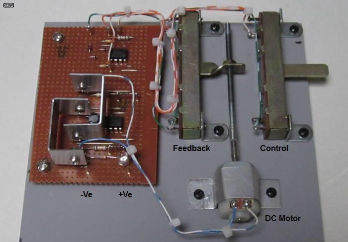
Figure 13 - Completed Demonstration DIY DC Servo System
The above photo shows the completed demo system. There is an extra dual opamp used as buffers for the pots, because the only ones I had to hand were 100k and would suffer poor linearity. Other than that, the circuit is identical to that shown above. Note the heatsinks on the output transistors, which get way too hot without the extra surface area to dissipate the heat. The heatsinks are small, but adequate. The feedback pot is driven by a length of 3mm threaded rod, with a rivet-nut attached to the pot actuator which was bent at a right-angle to make that possible. The extra caps (C1 and C2) weren't needed, and the gain is as close to perfect as one can hope for. The supply voltage is 12V DC. Resolution is determined by the motor - it's a 3 pole type, so the (theoretical) resolution is limited to 1/3 turn (120°) or 0.16mm, but this is not achieved in practice because the gain has to be kept low enough to ensure stability. This results in a dead-band of about ±0.5mm of control slide pot travel.
A servo system can also be made using a PIC, and the extensive processing available allows you to customise the way it works to ensure the best possible performance. However, this approach requires both analogue skills and good programming ability to get a workable solution. The PIC has the advantage of being re-programmable to perform differently, but of course you won't get a proper feel for the requirements of gain and stability unless you have already played with a purely analogue version.
Another option is to use the 'guts' (basically just the servo control board) out of a small commercial servo, and equip the outputs with (semiconductor) power switches capable of handling the voltage and current needed for a large motor and gearbox. Battery drills have a surprisingly powerful motor and a planetary gearbox that can handle a lot of power. While this is certainly a viable option, it may require quite a bit of development work to get it working properly, preferably without demolishing the feedback pot. In general, it would be wise to take this path with some care. There's a lot of scope for damage and destruction when you start playing with powerful motors equipped with high torque gearboxes.
However, if you want to explore this, you'll need to know how to change the appropriate parameters for the control IC. Whether this is possible or not depends on the availability of the datasheet for the exact IC being used. Without the essential data you'll be completely in the dark, as there's no way to know for certain what needs to be changed, by how much and in which direction.
High accuracy servo systems employ a number of discrete processes. The essential elements are proportional ('P'), integral ('I') and derivative ('D') with the system known as 'PID' [ 8 ]. In its most basic form, there is an amplifier to provide the 'proportional' part of the equation (linear gain), plus an active integrator and differentiator. While tempting, there are no plans to look into PID controllers at this stage, because they are far more complex than simple servos, and while essential for advanced production systems there's little advantage in hobby servo applications. In most hobby systems, the user is often the primary 'error amplifier'. As humans, we are able to apply the principles of PID naturally, and the electronic version (whether analogue or digital) is an attempt to replicate what we can do without even thinking about it. However, the electronic version can react much faster than we humans can, so PID control is common in industrial robots where both high speed and accuracy are paramount.
This isn't something new - Proportional controllers have been with us since the 1700s (purely mechanical of course), and were well advanced by time vacuum tubes (valves) were used for industrial processors. The formal (mathematically derived) version of a complete PID controller came about in 1922, originally for steering ships [ 9 ]. Fully electronic systems rely on the concept of negative feedback, first applied to telephone repeater amplifiers by Harold Black in the late 1920s.
While a full PID controller is capable of excellent results, tuning is necessary to account for system dynamics (in particular mechanical friction, inertia, momentum and/or resonance). These can be quite different even with identical machines if the process is even slightly altered between the machines themselves. Digital PID systems are now very common, with all functions able to be tuned to obtain the optimal values. Some digital systems offer 'self tuning' capabilities, where the controller learns the behaviour of the controlled system to arrive at settings that provide stable response and minimum settling time.
There's a lot of information on-line, with most of it from knowledgeable people in academia or commercial producers of PID controllers. Unlike the situation with hobby servos, the info you can get is based on maths and science rather than opinion or how model 'X' performs with servo 'Y'. While this might be helpful if you have the same model and servo, it doesn't provide any understanding of the system dynamics or any truly useful info if you have a different model and a different servo (or motor, or anything else).
Note that the derivative part of the circuit can be connected to the input differential amp's output or the feedback signal (with the polarity adjusted as necessary), depending on the particular system. Both methods are commonly shown in block diagrams and other literature, so have been shown here as 'Alternate Connections'. The existing connection (solid line) is removed if the alternate is used.
Figure 14 - PID Controller Concept
The drawing shows the essential parts of a PID controller, and is adapted from the schematic shown in an article published in 'Nuts and Volts' magazine in Jan 2005. The proportional gain block is the primary servo path, just like in any other servo amplifier. The integration circuit is responsible for correcting any accumulated error (it relies on the amount of error, its polarity and the time the error has been present). Finally, the derivative (differentiator) section monitors the rate of change of the error signal. By combining the three functions, it's possible to make the loop response faster that would otherwise be possible, but damped to ensure there is no overshoot or hunting. These depend on the load, and with simple (proportional only) servos it may be very difficult to set up a system that can cover a very wide range of output conditions. The PID controller has far greater flexibility than simply deciding to use a larger dead-band and is most likely to be found in industrial controllers, rather than hobby servos.
Figure 15 - Output Damping, Under-Damped, Over-Damped & Critically Damped
Using the test load shown, the level of damping of the above 'concept' circuit is controlled by the derivative output, set for three different damping levels. The integral was used only for the green (critically damped) trace, showing the correction for an 'accumulated' or long-term error. The gain of the proportional amplifier was unchanged for the three traces, and the integral and derivative signals were used to control the rate of change (damping) and final (long term) value respectively. The target value for the output was one unit, and this is provided by the integral amplifier given enough time (about 5.5 seconds for this example). Note that the capacitance is 100mF - 100,000µF, and simulates inertia. The inductor creates a long-term error, which is small but easily measurable. The final error after six seconds is around -2%, but that will reduce with more time.
The 'critically damped' result could not have been achieved using only a proportional control signal - it requires all three processes. The signals are also interactive, so changing the integral or derivative affects damping, but this depends on the time constant of the integral signal which is shorter than optimal for the example shown. Without the PID processing, the best you could hope for with a proportional only controller would be closest to the 'under-damped' trace, with a little less overshoot but a significant long-term residual error. All traces are very much load dependent, so if the load changes, the processing must also change to suit. There is no reason that only one integrator or differentiator be used, and Bob Pease designed a dual derivative servo to balance a ball on a beam in 1995 (see What's All This Ball-On-Beam-Balancing Stuff Anyhow).
The integral in particular generally requires additional processing over and above what's shown in the drawing, especially if the servo system ever runs 'open loop' (where the output's rate of change is limited by motor speed for example). This extra processing hasn't been included in the above, as it's intended to show the basic principle only - it is not a complete schematic, and is not something I'd suggest you build. If you want more information on PID controllers it's worth looking it up on the Net. There's a great deal to be found, and it will be apparent fairly quickly that this is a serious process and is not for the faint-hearted. I'm not going to pursue this further at this stage, because it's not germane to hobby servos. However, it was too interesting to ignore, hence the drawings and this brief introduction to the topic.
Most ESCs and servos use a fairly simple averaging circuit, an example of which is shown in the next section. Although the typical averaging circuit has rather poor performance, it's generally 'good enough' for the purpose. It's quite easy to make a much better circuit that responds faster and has far less ripple in the output, but for most hobby applications there really isn't any need. An averaging circuit based on a 4-pole active filter can achieve vanishingly small output ripple, with a response time that's at least four times as fast as a more 'traditional' approach. However, it requires quite a few additional parts, and this makes it less attractive for cost-sensitive applications or where every gram of weight makes a difference. Ok, the extra weight is minimal, but it's still something that has to be considered - especially for aircraft.
One major advantage is very high linearity. This is possible with a simple integrator, but it actually makes overall performance worse because there will be far more ripple at the output. Ripple cause the motor current to 'surge' at the pulse repetition frequency (typically 50Hz), and while it will be of no consequence for a large motor with plenty of momentum, it may become an issue with very small motors. While the ripple can be reduced easily, this is at the expense of reaction time. It's easy to get the ripple under 10%, but when you do, the integrator can take up to 1 second to reach 90% of the target voltage. This is going to be alright for some models, but far too slow for others. This is especially true for high speed models, where one second may be the difference between crashing ... or not.
With a repetition rate of 25Hz (40ms between pulses) and 50Hz (20ms), the average voltage is as shown in the table, assuming a 5V pulse. In reality, it may be more or less, depending on the accuracy of the receiver and its power supply voltage. It's easily calculated using the following formula ...
VAverage = pulse width / dwell time × voltage so ... VAverage = 1.5m / 20m × 5V = 375mV (for example)
It goes without saying that the average can easily be calculated for any pulse width, repetition rate and input voltage (but I appear to have said it anyway ). The important thing to remember is that the average value will change if the pulse repetition rate or amplitude change during use. The transmitter and/ or receiver may change the pulse spacing (depending on the design), and the receiver may not be capable to ensuring that the peak voltage remains steady. Either change will affect the way the servo or speed control reacts to your inputs.
| Pulse Width (5V Amplitude) | VAverage (50Hz/ 20ms) | VAverage (25Hz /40ms) |
| 1.0 ms | 250 mV | 125 mV |
| 1.5 ms | 375 mV | 187.5 mV |
| 2.0 ms | 500 mV | 250 mV |
The tricky part is working out the details for the integrator, as this determines the reaction time performance of the servo or speed control. The integrator circuit used in the ESC (next section) has a typical reaction time of around 500ms to get to within 10% of the target voltage. Having tested it fairly extensively (although not in a model), this appears reasonable, and is typically faster than most medium sized motors can accelerate or decelerate.
The ripple at the integrator's output is about 4% of the average value. This isn't wonderful, but it is generally acceptable. The ripple can be reduced with a simple integrator, but that will extend reaction time. If an infinite time is allowed for integration, the ripple will be infinitesimally small, and the converse is equally true. It's called compromise, and no circuit is ever free of it. A simpler circuit requires more compromises, but with endless resources the performance can approach the ideal.
If you need a faster reaction time and/ or less output ripple, you need a more complex circuit. I don't propose to describe a filter based integrator at this time, but one I experimented with has an output ripple of 1%, and is within 5% of the target voltage in under 80ms. No simple circuit can come close to this level of performance, but you'd only ever need it for extremely responsive servos or motors. A digital servo or ESC (using a microcontroller) can almost certainly offer a similar level of performance (perhaps even slightly better), but only if the programmer has written the necessary code and implemented it properly.
Making your own ESC for 'brushless DC' motors is possible, but isn't something that will be covered here. Brushed DC motor control is a great deal simpler, needing only a few fairly cheap parts. Mind you, you can buy them fairly cheaply too, so the only reason to DIY is to learn how to do so, or to make one that's a lot more powerful than those you can buy easily. The hardest part of the process is working with the narrow pulse width and the long delay between pulses. Whether it will work as expected also relies on your transmitter and receiver. Unless they provide consistent spacing between each pulse, decoding the signal becomes a great deal harder. The design shown below is (loosely) based on the circuit linked in the reference section [ 7 ], but is simplified for ease of description.
There are several considerations in the design of an ESC, and making a 'perfect' unit is generally not necessary. The variation in pulse width is small, from 1ms (idle/ stopped) to 2ms (full speed), but with a 20ms gap between pulses. While it's not overly difficult to still obtain a reasonable voltage change despite the very low duty-cycle, minimising ripple either makes the system unacceptably slow, or increases complexity (see previous section). If the duty-cycle from your transmitter is not consistent, then the task is a great deal harder. An inconsistent duty-cycle will cause the motor speed to increase and decrease (slightly), with it speeding up with a shorter duty-cycle and slowing down when it increases. This may not be a problem though.
Figure 16 - Brushed Motor Electronic Speed Control
The circuit isn't complex (despite initial appearances), and uses 1½ LM393 dual comparators. The circuit can be used with a supply voltage of up to 24V DC, and the motor current determines the type of output MOSFET and diode needed. If the circuit is used at voltages below 10V, a MOSFET designed for logic levels is recommended. Don't use a voltage of less than 7.5V (full load) or the regulator will drop out (lose regulation) and performance will be erratic. If preferred you can use a LDO (low dropout) regulator in place of the 78M05 (medium power version of the 7805), but make sure you follow the bypassing recommendations as they are prone to oscillation. The inclusion of the regulator also means you have an on-board BEC (battery eliminator circuit).
D3 will ideally be rated for the full motor current, and must be a fast or ultra-fast type. For small motors you can use the UF4001 or similar, or MUR1510 / HFA15TB60PBF ultra-fast diode for motors up to 10A or so. Use an IRF540N or similar MOSFET (or consider the IRF1405 - 5.3mΩ on-resistance and 169A peak). Note that very high current MOSFETs such as the IRF1405 cannot sustain the claimed current permanently, as the leads would melt! There is a vast range of suitable devices available for less than AU$2.00 (although you may need to buy in quantity to get a good price). In general, use a MOSFET (or paralleled MOSFETs) sufficient for not less than five times the expected current. For example, for a 10A motor, use at least a 50A MOSFET. For very high current motors, you must use paralleled MOSFETs, because the leads aren't thick enough to carry more than ~50A continuously. Likewise, even a fairly wide PCB track (250 mils/ 6.35 mm) can't carry more than 10A without substantial reinforcement, so hard wiring will almost certainly be necessary.
Be warned that there is no current limit, so the MOSFET will get very hot if a high power motor stalls. Although the IRF540N is rated for 33A, it will die a horrible death if you try to push it beyond a few amps without a heatsink (same goes for diode D3). A heatsink for the MOSFET and diode is highly recommended for anything more than ~3A. There are many options for the MOSFET and diode, so use ones you can get easily that meet your needs. There is also no under-voltage cutout, so care is needed to ensure that the battery is not discharged too far. This is especially important with Li-Po batteries, so consider adding the necessary circuitry to detect your desired minimum allowable battery voltage (3V per cell is recommended). Unless you are running multiple battery packs, a single low-voltage cutoff can be used for the complete system.
Setup calibration is needed. With a 1ms pulse train from a servo tester or receiver, carefully adjust VR1 until the motor is stopped, and there is no motor noise (noise indicates that there is some PWM signal getting through). Optionally, you may choose to have a small amount of the PWM signal present at idle - not enough to run the motor, but just sufficient to allow the motor to start with minimal additional input. As the pulse width is increased, the motor should start and run, with speed increasing as the pulse is made longer. At 2ms pulse width, the motor should be at or near its maximum speed. It may be necessary to adjust R8 (56k) to change the amplitude of the triangle wave (a larger resistance means a smaller peak amplitude and vice versa). Ideally, with a 2ms pulse from the receiver, the MOSFET should be fully conducting (not switching) providing maximum voltage to the motor.
With the values shown, the PWM frequency is a little under 920Hz, with a peak-to-peak amplitude of 517mV for the triangle waveform. The frequency can be reduced by increasing the value of C2, and amplitude increased by reducing the value of R8 (nominally 56k). Reducing R8 also reduces the frequency. For example, at 47k, frequency is 790Hz and triangle amplitude is 600mV p-p. Note that changing the setting of VR1 will also affect the frequency and amplitude of the triangle waveform. The change of control signal voltage with a pulse width from 1ms to 2ms is 800mV (1.2V at 1ms, 2V at 2ms). The motor will get 90% of the expected power within about 500ms.
The above circuit can be adapted to use LM358 (or similar) opamps, but there are quite a few changes needed to get reliable circuit operation. Unless a logic-level MOSFET is used, the opamp driving the gate must be run from the +12V supply. A 5V supply for the remaining two opamps does limit their performance, because the outputs cannot reach 5V - the maximum output voltage is about 3.5V in practice. I built an ESC using a pair of LM358 opamps (with the gate drive and input opamp (U1 A/B) run from the main +12V supply), and it works quite well. The pulse amplitude was limited to 5.1V with a zener diode and series resistor from the input opamp. You may find it necessary to use a trimpot in place of R8 to allow better control over the triangle waveform amplitude. If the amplitude is too high you can't get the full range (off to fully on), and if too low the speed range is limited.
This circuit is not designed for a reversible system with 1.5ms pulses to stop the motor. That requires a more complex circuit, and the sensitivity to pulse width variations is a great deal higher. This article is only intended to cover the basics of RC circuits, and a reversible motor system is more easily built using one of the commercial servo ICs (or you can 'gut' an old servo and use the PCB from that). Servos can also be modified for continuous (360°) rotation as described above. However, service life will be compromised if you expect to run them for long periods and/or at high loading.
Given the comparative complexity of reversible ESCs, along with the narrow pulse widths that the circuit has to work with, it's no surprise that many people find it's easier to use a PIC or other microcontroller, as most of the complexity becomes a software problem rather than hardware. If it doesn't work exactly the way you want, then it's (hopefully) a simple matter to change the program, without the need for major changes to the circuit itself. Provided the basics are in place and work properly, there's no need to redesign a PCB to accommodate the revised software. Of course, this depends on one's programming skills and the capabilities of the PIC itself.
When it comes to brushless motor ESCs, the general approach is almost always to use dedicated ICs and a microcontroller. TI make a 3-phase driver (DRV8302) which is designed to drive output MOSFETs, and it relies on an external MCU (microcontroller unit) to provide the smarts needed to ensure proper rotation, receiver output decoding and fault monitoring. There are many other ICs dedicated to the task such as the L6235 or MC33035 (both require Hall sensors) or the A4960 (sensorless BLDC motor driver). The overall design is not trivial, despite the availability of ICs for the purpose. Given that commercial versions are available at relatively little cost, it's probably not sensible to try to build your own. This hasn't stopped many people though, and DIY versions are shown on many sites on the Net. If this is something you wish to look into, do so by all means, but I will not explore that option here.
While it may not seem like it, a simple ESC such as that shown in Figure 16 has regenerative braking by default. If the motor is driven faster than the applied voltage would normally achieve, the motor acts as a generator and forces current back into the circuit. The intrinsic diode in the switching MOSFET conducts and the current passes through that and back to the battery. You have control by turning on the MOSFET (using PWM), and when the maximum braking effort is required, the speed control will be reduced to zero. This can only work if the motor is driven by external forces (e.g. gravity).
This isn't capable of providing the same braking effort as you get by shorting out the motor with a separate MOSFET (dynamic braking), but it will work in situations where limited braking capacity is required. It almost certainly won't work with anything propeller driven, but braking isn't likely to be needed with such systems anyway (planes can't be stopped in mid-air). For ground based models that may be expected to negotiate steep inclines the natural regenerative braking available may be as much as you need.
Traditional braking is achieved by using a MOSFET to short the motor. This provides the maximum possible braking force (without resorting to reverse polarity) but it is not regenerative. The energy from the motor is dissipated as heat, mostly in the motor itself. In theory, it may be possible to use the motor's back EMF to power a switching inverter that has a low voltage, high current DC input and the output puts 'excess' energy back into the battery, but this would require a fairly complex circuit that would not be economical for modelling. The alternative is specially wired motors designed for the purpose. Trains ('real' ones) and modern electric cars use a combination of regenerative and dynamic braking, and also provide friction brakes as these are necessary to bring the vehicle to a complete stop. This cannot be achieved by dynamic or regenerative braking alone, nor can they provide brake holding power to vehicles that are parked.
To see just how regenerative braking can work, look at Figure 9 above. The back EMF generated by the motor is less than the supply voltage, because the motor was under load. As the load is reduced, back EMF increases (towards zero volts). Should the load (such as wheels driving a vehicle) try to cause the motor to go faster than its no load speed, the generated voltage will be greater than the supply, and will fall below zero volts. This causes the MOSFET's diode to conduct and pushes current back into the battery.
For speed control, you ideally need a tachometer. One solution is a dedicated tacho-generator, or you can use a motor (such as the HDD motor referred to earlier), or a rotary encoder. The rotary encoder can be home made fairly easily, provided you can print onto a plastic film (there are specialty films for laser and inkjet printers). While the circuitry needed for a rotary encoder is more complex than using a motor as a generator, the results can be extremely good, with very high resolution and minimal drift.
When a slotted disk passes between an LED and phototransistor, the duty cycle remains the same regardless of the speed. That means the average output remains constant without further processing. It's necessary to provide a constant pulse width regardless of speed, so the result can be integrated to obtain a voltage that depends only on the speed of the motor. Fortunately, a 555 timer is ideal for this purpose, provided the signal from the encoder has a fast risetime. If possible, the frequency from the encoder should be much higher than the motor speed, so if you need a motor to maintain a constant (say) 6,000 RPM, it's better to have the encoder output at 1kHz than 100Hz (10 'slots' vs. 1 'slot', respectively). Doing so makes filtering easier, and improves the response time by a factor of 10. It might be quite alright to have a 100ms response time for one design, but it may be far too slow for another.
We tend to think that a motor speed of 20,000 RPM or more is pretty fast, but it's only 333.3 revs per second, so a single slot encoder will have an output frequency of 333.3Hz. In electronics, this is slow, and it's easy to process signals up to 10kHz with even very ordinary parts. This would allow speeds of 600,000 RPM with a single slot encoder, or 60,000 RPM with 10 slots. You can use as many or as few slots as needed to get a frequency within the 'friendly' zone of between 500Hz and 5kHz. I call this 'friendly' because simple circuits using cheap ICs can handle that range with ease, but still have very good accuracy and linearity.
Even though the frequency range is 'friendly', that doesn't mean that an over-simplified circuit will achieve good results. I like simple circuits, provided they are also elegant and perform as intended. This isn't possible if the design is over-simplified, because results will not be predictable. While you can (nearly) always end up with a circuit that works, it just doesn't work as well as it might if a little more thought goes into the design. In the drawing, note that the LM393 is a dual comparator, and not an opamp. Opamps are not fast enough to work in this circuit. The second half of the LM393 is not used in this circuit. You can also use the LM/LP311 single comparator if preferred, but it has a different pinout.
Figure 17 - Frequency To Voltage Converter (Tachometer)
A frequency-to-voltage converter is shown above. It uses a photo-interrupter to detect the motor RPM, with as many slots (or transparent sections) as needed to get a useful frequency range. As shown, it's perfectly usable for frequencies from 500Hz to 4kHz, providing an output voltage from 0.5V to 4V over that range. The slotted disk is attached to the motor shaft, and with (say) 30 slots, will be accurate over the speed range of 1,000 RPM up to 8,000 RPM. Adjust the number of slots to change the speed range, or use different values for C4, C7 and C8. The output of U3 is a series of 200µs pulses at a repetition rate determined by the RPM, and these are integrated by the output filter. You may find that performance can be improved by using the 7555 (CMOS version of the bipolar 555), as the output can swing to the supply rails (0V and +5V) provided the load current is low enough.
The two integrator (low pass filter) sections have a -3dB frequency of 72Hz each, with a final -3dB frequency of 45Hz. The filter has a high output impedance, and will require a buffer before the servo speed controller unless it has a very high input impedance. This entire circuit can be used in place of the feedback pot in Figure 12 (which would be simplified because bi-directional operation isn't supported with the tachometer as shown). The output must be buffered so it can drive the 2k2 input impedance of the error amplifier. VR1 is used to calibrate the monostable (based on U3 - 555 timer) and the integrated output pulses produce 1V/kHz.
Figure 18 - Voltage Vs. RPM (Or Pulses/ Second)
This shows the circuit's linearity, providing almost exactly 1V/ 1,000 pulses per second (1V/kHz). The frequency can be expanded or reduced by modifying the monostable's timeout (vary C3), but the filter also needs to be re-calculated. As seen, the voltage is stable within 15-20ms. A better output filter can improve that, but use of a high-Q filter is not advised because it will cause overshoot. The amount of output ripple is determined by the integrator and applied frequency, so it will always be a compromise. If you were to use an active filter for the output, it has to be a Bessel alignment (minimum settling time) or you'll get overshoot at the output. The filter shown has a Q of 0.5, where Bessel is 0.577. The difference between the passive filter shown and an active filter based integrator will vary between negligible and extreme, depending on the filter's complexity. As with an input pulse integrator for a servo or ESC, a properly designed filter can give very fast response and low output ripple.
It's possible to use much simpler circuitry to get a result, but it will not be as good as shown above. It's often tempting to use the simplest circuit that will work, but that will bite you on the bum if it turns out to be inadequate. Likewise, there's no good reason to make the circuit more complex to get improved performance, if the improvement can't be realised by the rest of the system. For battery powered systems in particular, the performance of everything will be degraded as the battery discharges. A tachometer that can give you a feedback signal from zero to maximum in under 20ms will outperform almost any motor.
While the circuit can (in theory) handle an input frequency of up to 5kHz, the 555 timer doesn't have the output swing to allow that with a 5V supply. A higher supply voltage can be used, but that may add needless complexity to the final project. The supply needs to be regulated to ensure a consistent result. The 200µs pulse width can be changed by varying the value of C4. Make it 1nF to get a 20µs pulse width (good for much higher speeds, but reduce C3 to around 100pF) or 100nF for 2ms (for very low speeds). R10 and VR1 can also be changed if required - the system is flexible to suit your needs.
Note that if you increase the pulse width, the final filter must be changed to suit or ripple will be excessive for low speeds. Likewise, if pulse width is reduced to allow for higher speed, the filter time constant can be reduced for a faster reaction. It's unrealistic to expect a tachometer to be able to cover a range of more than 10:1 without using a more advanced integrator, especially if a fast reaction is expected. However, there's not much point using a fast integrator if the motor only spins up slowly. For example, if the motor can't reach operational speed for (say) 10 seconds, then you don't need an integrator that responds in 10ms.
You can also use a Hall-effect switching IC to provide feedback, but you need at least two magnets on some part of the rotating system. While one magnet can also be used, it will cause the system to become unbalanced unless a counterweight is provided.
The various systems described above all rely on some form of position monitoring. While this is generally a fairly ordinary potentiometer (pot) for common hobby servos, there are often requirements for much greater resolution. Industrial systems will almost invariably use monitoring processes that provide high accuracy with extreme longevity. A typical 'ordinary' pot may withstand perhaps 100,000 operations, but that could easily be exceeded in a few days with a high-speed machine.
Opto-interrupters are common (as described in the previous section), but may suffer from limited resolution. There's a limit to the number of slots one can cut into a disc, and a definite limit to the speed available from the pickup photo-transistor. All forms of position sensor are limited - if you need exceptional resolution you must accept that speed cannot be too high. Likewise, if you need very high speed then resolution is compromised. Tacho generators are at the bottom of the pile for accuracy, and cannot provide positional information.
A 'resolver' is specialised analogue encoder that incorporates a rotary transformer and two sense coils, 90° apart. These can provide very high resolution for angular position and can also be used to determine shaft speed. They are at the upper end of the price scale, and require fairly sophisticated circuitry to provide the drive signal and analyse the output signals. They are generally very robust, and well suited to adverse conditions (heat, shock, vibration, etc.). There are no electronic parts within the resolver itself - it's completely passive.
Where requirements don't involve high accuracy or long service life (such as hobby servos), then there's no good reason to pay top dollar for very sophisticated sensors. It's not helpful to have a $500 sensor on a $20 servo, but the reverse may also be true. Attempting to get repeatable and accurate results from cheap sensors is equally unwise. This topic will not be continued here, because there are so many variables that I can only scratch the surface anyway.
As with many ESP articles, there's a lot to take in, but hopefully this article has helped your overall understanding of servos. They are used in so many applications that modern life just would not be the same without them, yet to most people they are very much an unknown technology. There probably isn't much call for a servo in an audio system (which is the main audience for the ESP site), but there are many 'non-audio' projects and articles, so it's not out of place to discuss these essential pieces of technology. Having said that, servos are used in most amplifiers to maintain bias current with varying temperature, and are sometimes used to eliminate DC offset in opamp and power amp circuits.
Servos and ESCs are now much more common than ever before, with people experimenting with robotic systems and a huge number of multi-rotor 'drones' now being used for tasks such as real estate agents providing arial views of properties, shark patrols (important in Australia), or just being a general nuisance (usually unwelcome everywhere). Major on-line retailers are talking about using drones to deliver goods (not sure if that's a good idea or not), and of course we have self-driving cars - either just around the corner or years away, depending on who's discussing them.
It's fairly obvious that a self-driving car (or truck) will use servos for everything that's normally done by the human driver, as this is exactly the kind of thing they are ideal for. Any autonomous device needs servos for control, since the requirement as to what to do is just a computer output, and it has to be interpreted into mechanical motion. At the very least, such servos will almost certainly be PID controllers, because of the need for very high accuracy and completely predictable behaviour. They will require even more processing to account for highly variable conditions, and to add fail-safe provisions to prevent accidents even if a system goes awry.
We can expect that servos will become far more popular (and more advanced) than they are today, with new techniques and more accurate positioning systems. Hobby servos are out of their depth in any system where lives are at stake, but they too will evolve. There is evidence of this evolution already, but it will almost certainly accelerate in the coming years.
We might as well get to know these systems before they are advanced to the point where mere mortals can no longer figure out what they do and how they do it. This is what happens once something is converted into microprocessor code that no-one will give you access to (it can be hard enough getting good info on some of the current analogue ICs). While the underlying electronics will change, the overall principles remain the same as they are now. The designers of fully digital systems also need to know the interactions between the electronics and mechanical parts, or it's impossible to get a fully optimised system. Fortunately (or unfortunately, depending on how you look at it), many of the tasks that used to require a physical prototype can now be simulated with the appropriate software, so the 'hands-on' part of the design process can sometimes be dispensed with. This is a shame, because that's the best way to learn how these systems really work.
I briefly touched on PID controllers, and this opens a vast can of worms. These controllers can be very difficult to set up properly, and there are (many) entire books on the subject. The extra functions increase performance, but at some cost. The greatest cost these days is the time needed to optimise the system, especially for industrial processes where time constants are measured in hours or even days. Even for faster systems, it's not always easy to get the optimum set of parameters for the three functions, and it's not something I intend to cover.
If you are working with ESCs for high current applications, be aware of component (MOSFET and diode) lead sizing and the total current your system will draw. Once you get over 20A or so, precautions must be taken to ensure that everything can handle the current without overheating. This applies to PCB traces and component leads. Just because a MOSFET (for example) is rated for 100A, this does not mean that the leads and soldered connections can carry that much current without a serious temperature rise. Paralleled MOSFETs and 'off board' wiring will usually be needed with very high current circuits to ensure that the component leads aren't stressed by thermal cycling or over-current. Consider that a typical TO-220 component lead has an area of around 0.6mm², which would normally have a current rating of about 7.5A. This is extended (considerably) only because the lead is short and assumed to have good heatsinking at each end.
Servos are not simple, despite appearances. There are electrical and electromechanical factors at work every time the position is changed. How well (or otherwise) the servo achieves its target depends on so many factors that it's hardly any wonder that most people simply rely on a dead-band to make the system stable. This always means that there is some residual error, but for many things it doesn't matter. For others, it may be life or death, so it pays to know the subject and choose wisely.
One thing is certain - the more you play around with the circuits and motors, the more you will learn about the all-important interactions between the electronic and mechanical components. Play with circuits, make a servo hunt because of excessive gain, and examine the effects of damping - both electronic and mechanical. This kind of hands-on experience will improve your appreciation for the techniques used now, and more advanced approaches such as PID controllers. It doesn't matter if the end result is hardware of software, as long as it does exactly what you want, when you want it.
Please Note: There are many other references that were used to double-check the validity of claims made, and to extract a few finer points about the systems and how they worked. Not all have been included above, as the reference list could easily become unwieldy. For those interested, the list above is a good starting point, but it's surprisingly easy to look at ten different sites (and/ or books) and get ten different answers. It's up to the reader to determine what looks as if it might be real and what is obviously (or not so obviously) bogus.
Main Index
Articles Index