
|
|
| Elliott Sound Products | Project 79 |
Switch on one unit, and everything else you need turns on automatically. Master-slave power switching can save the tedium of turning on half a dozen different things, when one should be enough! As a bonus, many things draw significant "standby" power, even when supposedly turned off. This is another project created purely from necessity. In my case, it was to switch on all my computer peripherals when the PC was turned on, but I shall be building another very shortly to do the same with my Hi-Fi equipment. It's worth noting that the use of any form of master-slave switching with many PCs may be unreliable, because almost all machines these days have a low power supply that runs all the time. For PCs, use Project 118 as it is 100% reliable.
This project was updated in May 2019, with the addition of Figure 1b, a wide current range circuit. It will operate from as little as 20mA, yet still handle a load of 10A or more with ease. This should be the circuit of choice if you wish to build the project, but for more mundane applications (that draw a consistent current when operating), the other options are still available.
When a system consists of a number of components, there is the ritual of ... switch on the preamp, power amp(s), subwoofer, CD player, and maybe a crossover or equaliser. It's not hard, but it is tedious! Then, one must remember to switch everything off again - this is not always easy after a nice long listening session, beautifully accompanied by a lovely Cabernet Shiraz that was just pleading to be demolished. 
No longer must you suffer so. When a load current is sensed from the 'master' unit, this circuit will automatically switch on everything connected to the 'slave' mains output. The only thing you need to do now is turn on the preamp (for example), and all the other units spring into life, and equally, gracefully fall asleep again when the master unit is turned off.
| WARNING: This circuit is directly connected to and controls household mains voltages, and must be built with extreme care to ensure the safety of you and your loved ones. All mains wiring must be segregated from low voltage wiring, and in many countries, mains wiring must be performed only by suitably qualified persons. |  |
Please ensure that you heed the above warning. One small mistake could mean the end of you (or someone else!). I have colour coded the wiring in the diagrams (according to the international standards) so that the mains is easily recognised. Never use ordinary hook up wire for mains voltage connections, and ensure that all solder joints are secure before soldering and are insulated against accidental contact.
NOTES:
|
The heart of the circuit is TR1, either a completely ordinary small low output voltage transformer or (preferably) a current transformer. A standard transformer is connected in reverse, and used as a current transformer. A power resistor shunts a good proportion of the current away from the transformer, since most small transformers have an excessively high secondary resistance. Never use the circuit without the shunt resistor, as the output voltage will reach dangerous levels without it.

| Please note: this is the least recommended version, as it will be difficult to ensure good insulation for the power resistor and wiring to the transformer. While this is the exact circuit I built when I needed it, I have since availed myself of a selection of current transformers. These are a far safer option, and I suggest that if you build the unit, you use either the circuit shown in Figure 1a or (and better still) that shown in Figure 1b. |
I used a 5VA, 240V to 18V transformer (because I had one), but anything with 9V to 15V secondaries will work just as well. The resistor should be a 10W wirewound type - make sure that the terminals are well insulated against contact, and keep all wiring well clear of the resistor. Under normal circumstances it will get quite warm at full rated power - if you use my recommendations, maximum dissipation will be 4W at rated current. Feel free to reduce the value of the resistor if higher currents are expected, or ...
The resistor may also be reduced if a lower secondary voltage transformer is used. Remember that the transformer is now a step-up unit - the small voltage across R1 is stepped up by the turns ratio of the transformer. A voltage of 1V across the secondary winding will create a much higher voltage on the 'primary', so some care is needed.
In general, I much prefer the version shown in Figure 1A. Use an AC-1005 current transformer or equivalent, as it's smaller, lighter and cheaper than even a small mains transformer, and you don't need the power resistor or exposed mains wiring.
220 - 240V Operation 110V-120V Operation TR1 12V secondary, 220-240V primary TR1 6V Secondary, 110V primary R1 1 Ohm R1 0.5 Ohm
With the values shown above, the maximum load current of the master unit should be limited to about 2A (4A for 110V), and this will be more than enough for most preamps, computers, etc. In theory, this will give an RMS voltage of about 30V on the primary, but in reality it will be typically somewhat less than this. It is a good idea to check the actual voltage obtained from the transformer. If it exceeds about 30V, then reduce the value of R1 appropriately.
Note - If the master unit draws more than 1-2A, use the circuit shown in Figure 1a or 1b !
VR1 is used to set the sensitivity of the circuit. This may not be needed in some cases, but it is recommended. The sensitivity should be set to ensure that the relay(s) activate reliably when the master unit is switched on and off. I had to include the sensitivity control in my unit, because the PC draws a small quiescent current (as do almost all of them now) which was sufficient to activate the relays as soon as the lead was connected. (I was not amused, since I then had to dismantle everything and modify the unit. Grrr.) Since I no longer use it with my PC, it means I can adjust it for any master load over a few Watts.
Warning: If the sensitivity is set too low, Q2 may overheat! This is because it will not be saturated, and the full voltage does not appear across the relay. The transistor will have the relay current flowing through it, and some voltage across it - this equates to power, and power means heat. Such a condition will ensure that the transistor will fail at some time in the future (probably after you have forgotten how you wired the circuit, and at the least convenient moment - as always). You can add a LED with 2.2k series resistor across the relay if you'd like an 'activity' indicator.
The transistors as shown are BC549/559, but you should be able to use any readily available small signal transistors without any changes. Neither transistor dissipates significant power, and the average current is under 100mA. Choose devices with a hFE of at least 100.
Figure 1 - Current Sensing Slave Power Switch
Figure 1 shows the schematic of the main controller. Remember that TR1 is connected with the secondary (low voltage side) in parallel with R1 as shown. The diodes shown in parallel with R1 are optional, but are useful for medium current levels (up to about 5A). 1N5401 or similar diodes can handle 5A easily, and the circuit can detect a current of anything from about 75mA to 5A RMS. The input and master connections cannot be reversed! If you accidentally wire the circuit with them interchanged, once powered on, it will stay on, with the peripherals maintaining the current flow through TR1. Figure 1A shows an alternate version that is ideal for higher currents - up to 10A or more is easy.
NOTE: If you use the auxiliary power supply output, do not use the unit with the control circuit 'floating', as any internal insulation failure will render the unit extremely unsafe, and may cause risk of electrocution or fire (or both). When used in this manner, the protective earth connection must be used as shown.
RL2 is optional, and is needed only if the 12V (nominal) external DC supply is required. Power is supplied from an external plugpack, as these are readily available and relatively low-cost. Diodes are 1N4004 or similar (other than the optional diodes in parallel with R1, which should be 1N5404 or similar), and capacitors should be rated at 25V.
Do not use a double pole relay with one pole for the 12V supply (instead of two relays). Although mains rated relays may be 'safe' in this configuration, there is too much risk of mixing up the terminals, and sending deadly mains voltages out the auxiliary connector. It is also much harder to ensure that the wiring is properly segregated.
If the Auxiliary DC is not needed, then you can omit RL2, J2, D2 and C2, and run the unit from an internal supply (as shown in Figure 2) or from a 12V DC plug pack external supply. J1 is only needed if an external supply is used, otherwise, it too can be omitted.
If you plan to use this circuit for high power appliances (such as power tools), do NOT use the resistor/ transformer arrangement shown above. Use the Figure 1a current transformer circuit, which allows you to wind one or more turns of mains wire through the core, and derive an output voltage from the secondary. Suitable current transformers are available from most major resellers for no more than $5 or so, and are a far safer option. A 5A current transformer is ideal for almost any load because we don't care if it saturates. This is a detector, not a measuring instrument.
So, if your 'master' load draws more than 1A or so, use the following circuit. Current transformers are specifically designed for monitoring current (I'll bet that came as a surprise ) and allow you to simply wind one or two turns of mains insulated wire through the core. See Project 139A and the section on current transformers in the transformer articles for some information about current transformers and how to use them.
Figure 1a - High Current Slave Power Switch With Current Transformer
When you use a current transformer, the number of primary turns needed depends on the transformer itself, and the current your appliance draws. With the transformer shown in Project 139A, try 2 turns if your load draws around 1A, and you can reduce the number of turns for higher currents. For example, for a 10A appliance you would only need a 1 turn primary, but there may not be enough range for adjustment for lower powered equipment. Note that you can't get less than one turn for the primary. For low current (100mA or more), simply use 10 turns through the core to increase the sensitivity, and reduce the fuse from 10A to 2A or so. Higher sensitivity is possible, but it may be difficult to fit many more turns through the 9.5mm hole in the core.
In this application, we don't really care if the current transformer saturates, and frequency response is unimportant. Therefore the 'burden' resistor can be higher in value than would be the case for a measurement system, and more primary turns can be used. The 10k pot shown in Figure 1A will give a fairly wide range of adjustment. The 5.6V zener diode prevents the output voltage from reaching possibly dangerous levels - please don't assume it isn't needed!
I tested an AC-1005 current transformer (see the datasheet) and found that it will work with a single primary turn at about 0.5A, although I consider that to be borderline. If you do need to sense a low current, I suggest two or more primary turns. It will still work at 10A (or more), and the zener (400mW or 1W types are both fine) across the secondary will prevent excessive voltages from being developed. I also tried the current transformer with 8 turns, and it seems to be quite reliable at 125mA (100mA with 10 turns). The switched 12V output can use a relay if preferred, and likewise, the simple circuit shown here can be used with the Figure 1 circuit as well. Maximum output current is ~50mA, but that can be increased by using a BC640 instead of BC559 for Q2. If you need to monitor very wide range current, then use the circuit shown in Figure 1b.
Many high power appliances (such as power tools, where you may want to switch on a dust extractor for example) draw a very heavy current during startup, a relatively small current when just spinning but not actually cutting something, and a (variable) medium-high current (based on the rated power) when under load, so you need a fairly wide range current detector. The current transformer is absolutely the best choice!
In all cases, it is vitally important that the main relay (RL1) is be rated for the full AC load current and voltage that you will be controlling. Never use a relay that is not suitably rated and designed for mains switching, as either electrical breakdown of the insulation or contact failure (or both) may result.
As shown, the circuit is designed for 10A relays, having a coil resistance of ~220 ohms or more, although it will drive coils with lower resistance as well. A coil resistance of 100 ohms is the suggested minimum. If you need a more powerful relay, use a 24V supply (and a relay with a 24V coil), as this reduces the current that Q2 has to pass. In extreme cases, Q2 can be a Darlington transistor.
Note that the control electronics are earthed to the mains ground. This is essential for safety and the auto-switching system must not be used with a two-wire mains lead - it must be earthed!
Some appliances can draw a very wide range of current in normal use. While adding turns to the current transformer makes it more sensitive to low currents, if the appliance also draws a high current (up to 10A for 230V, 20A with 120V appliances) that may well cause the CT to overheat. For example, if you wind ten turns for the primary to get sufficient sensitivity for the 'idle' current, when the appliance draws maximum current you'll get an output current of 100mA at 10A or 200mA at 20A. The winding resistance will be between 40-50 ohms, so the winding dissipation could reach 2W and it will run hot. If we do need to be able to sense current from ~50mA up to 10A or more, the circuit gets a little more complex.
Figure 1b - Wide Current Range Slave Power Switch With Current Transformer
Using a single low-cost dual opamp, we can achieve the best result possible. U1A is an amplifier, and R2 (1MΩ) is used to ensure that the output remains at ground potential in the absence of signal (pin 2 is raised to about 12mV). The gain is determined by R3 and R4, and is x100 with the values shown. The output passes through D2 (1N4148) and charges C1 to about 10V. U1B is configured as a Schmitt trigger (via R7), so switching action will be absolute - there is no 'in-between' state. The output of U1B is normally high, and when a signal is detected it switches low, turning on Q1.
It's not as complex as it may appear at first, and everything will fit onto a small piece of Veroboard. Sensitivity with a 1,000:1 current transformer is about 20mA with a single turn! Even with 10A or more, nothing is stressed in the slightest. This circuit may be more complex, but it's also far more capable than the others shown. If I need to build another 'master-slave' system, this is the circuit I will use.
While the sensitivity range is already very wide as shown, it can detect as little as 10mA mains current (still with only one turn through the current transformer) by omitting R3. U1A then acts as a comparator, and will provide full output when the input level exceeds ~12mV. However, I recommend that R3 is installed when the unit is built, and if you can't get sufficient sensitivity it can be removed (or replaced by a higher value). Also, C1 (shown as 10µF) maintains the output for about 10 seconds after the input current stops, and this can be increased by using a larger value if necessary. This could be very useful if the controlling appliance changes its current draw over a wide range during use.
A suitable internal supply is shown in Figure 2. The transformer is used in the normal manner - if you use the Figure 1 circuit, do not get the two transformers mixed up when wiring! This may be surprisingly easy to do, since the transformers may be identical (the use of two identical transformers is perfectly acceptable). I very strongly recommend that both transformers be fitted with thermal fuses if possible, or at the very least, use a fuse in the input of the auxiliary supply as shown. Small transformers are not often renowned for their build quality, and a labour saving circuit that burns down your house is not entirely satisfactory. If possible, use the Figure 1A version.
Figure 2 - Internal 12V Supply
The supply shown will give a nominal 12V, and will normally be low power, since the only real load is the relay(s). If the auxiliary DC is not required, C1 may be reduced to about 470uF (which is still better than many transformer based plug pack supplies!). Diodes are 1N4004 or similar, and C1 should be rated at 25V. A 5VA to 10VA transformer will usually be adequate. If the auxiliary 12V output is used, it should be limited to no more than 500mA for a 10VA transformer.
A power supply option that is now becoming economically viable is to use a small switchmode power supply (SMPS). These readily available plug-pack (wall wart) supplies are now cheaper than buying a transformer, diodes and a reasonable sized filter capacitor.
The latest versions of these draw almost no power when not being used, and can either be used as purchased or (if you are careful !) the PCB can be removed from the housing and installed inside the master-slave switch itself. A typical SMPS board is pretty small - about 60 x 30 x 20mm for a 12V 500mA power supply for one that I've used in a few projects, and the output voltage is even regulated. The power supply article referenced just below shows a typical PCB extracted from a reasonably typical plug-in SMPS unit. Some suitable candidates I've tested and used draw less than 300mW with no load, and are by far the most efficient option.
Another possibility is to use a so-called 'transformerless' supply (see below for some details of a commercially available unit), but these are a bad idea unless you are completely comfortable (and competent) working with mains voltages. Although often suggested for projects of this type, they are very dangerous because everything is live. There's also a small problem that relays draw a bit of power (around 0.5W is typical), and a transformerless power supply can only operate satisfactorily with a constant load. It will be hard to build a unit that runs at less than 1W and gives acceptable regulation, and the mains capacitor may be quite large and expensive. The circuit will also have an absolutely dreadful power factor, which is common for these supplies. This can be ignored though because of the very low power.
For more information on why you should avoid using a transformerless supply, see Small Power Supplies. As you will learn from that article, even major corporations can get things horribly (and illegally) wrong easily. It's even scarier when they refuse to admit that they stuffed up badly. The version shown below does work well enough though, even if quiescent power is a bit higher than is desirable.
In case you were wondering ... Why did I choose a transformer rather than an IC opto-isolator? Quite simple, really. Opto-isolators are almost ideal, but need a PCB. Veroboard and similar strip boards are extremely unsafe with mains voltages, and I wanted this in a hurry (as usual!). Never use strip board with mains voltages - it is just not designed for this!
To use an isolator, I would still need the power resistor, but its value would need to be higher (more power loss, more heat) to generate enough potential to operate the LED in the isolator. Or, I could use diodes to get the voltage drop needed. These would need to be high current types to handle the inrush current of even relatively small 'master' appliances. Either way, I would (and therefore so would you) need to obtain the needed bits, where the design shown can be made with parts from the 'junk box' - a transformer from an old plug pack supply, a few very common diodes and transistors, and a relay or two.
There is also the problem of limiting the LED current for overloads or even normal operation, and this can get quite irksome. A balancing act between sensitivity and ease of construction, safety and cost. Overall, the method shown is safe, easy to implement, and very satisfactory. Since almost any mains transformer can be used (for example, I have some 110V transformers I could have used - they are no use to me in Australia for anything else). The answer to the next question is "because I couldn't find one immediately" .
Apart from anything else, most constructors will not have 'odd' voltage transformers lying about, so will have to use those intended for their normal mains voltage, so it was better (for you, anyway) that I used a standard transformer for my testing. This also ensures that the insulation is rated to the actual voltage in your country, a not entirely unimportant consideration.
Please do not be tempted to use anything other than a mains transformer, unless it is rated for the full mains voltage. Typically, mains rated transformers will have an insulation breakdown voltage of 2kV or more between windings. This is your safety barrier, and as such it is very important that it really is a barrier. For higher current loads, the current transformer option is by far the best, and that's the one I recommend unless you have no other option (due to low current draw from the master appliance, for example).
You might also wonder why I didn't just use the output of the transformer to power the relay (via a diode and capacitor). The answer is again very simple. If your master device draws (for example) 400mA from the mains, only a small part of this goes through the transformer winding. The output voltage will be considerably higher, but at even lower current. With a carefully selected relay and transformer, this is possible, but generally, the power available will be too low - hence the amplifier circuit.
In short - this is a very basic circuit that works well and reliably with a wide range of controlling appliances, and it has a nice 'techie' touch to it as well.
In the interests of providing all the info I could, I obtained a commercial master-slave switching power board. Predictably, it also has metal oxide varistors (MOVs) to provide some protection against transients, and like most 'surge protected' power boards the claims are somewhere between specious and nonsense. One thing that has been done properly is to incorporate a thermal fuse with the MOVs. After a number of voltage-clamping operations (the number depends on the current), MOVs have an increased likelihood of becoming conductive at normal mains voltages. Without the thermal fuse they can easily set the PCB and/or plastic case on fire!
I am actually in (minor - and negative) awe of the power supply design - the manufacturer/designer has managed to make the circuitry draw over 1.2W at idle, yet the highest I can calculate or simulate is around 560mW using the same topology for the power supply. I don't know how they managed to achieve this result, but it's certainly not to anyone's benefit. The discrepancy isn't life-changing, but it is rather puzzling. I can only assume that there's a small leakage current through the MOVs (even though the unit has never been used).
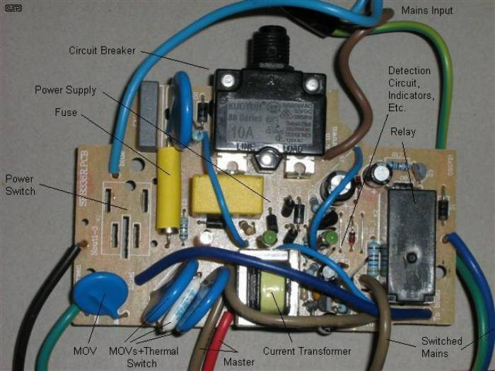
Figure 3 - Commercial Master-Slave PCB
The power supply used is a so-called 'transformerless' type, but this is alright in this application, because the entire circuit is completely isolated from the user. However! Be warned that these circuits are dangerous, and you can't work on them easily. Please don't be tempted to use an isolation transformer, because there are still lethal voltages throughout the circuit, and your safety switch will not operate because of the isolation transformer!
Current sensing is done with the little current transformer visible in the bottom centre of the photo. This is obviously specially made so is smaller (and cheaper) than my suggestions, but will be unobtainable almost anywhere ... unless you want to buy 1,000 or more of course. For anyone who wanted to do so, a small transformer could be built using a high permeability ferrite core. The mains 'winding' only needs to consist of a single turn of mains-rated insulated wire - this also eliminates the parallel power resistor and ensures electrical isolation. The secondary winding might be about 1,000 turns of fine wire (0.05mm or thereabouts). You would need to experiment with the current transformer loading to obtain acceptable sensitivity. True current transformers are a bit of an art-form to design, but it can obviously be done. Alternatively, just buy a small current transformer (see the section based on Figure 1A).
The detector circuit shown in Figure 1 can be used without modification, other than using a single 24V relay and omitting the auxiliary supply.
The circuitry of the commercial unit is different from mine, but it serves exactly the same purpose and works in an almost identical manner. There is no facility for a sensitivity adjustment, so many appliances will not activate the unit at all. I measured the sensitivity at about 125mA, or 30VA (approximately 30W for an ideal load). It drops out when the load falls to around 22VA or so. Because the circuitry is fairly crude, there was noticeable variation between tests, but this should not be an issue in normal use. The low sensitivity means that the master device must draw well over 30VA to ensure reliable operation. A TV set will be fine, but a preamp will almost certainly not draw enough current to activate the switch. At least if you build your own you can have some control over its sensitivity.

Figure 4 - Commercial Power Supply
The power supply is (more or less) as shown above. C1 must be an X-Class cap, as these are the only suitable type for this application. Note that there are a couple of differences between my recommended supply arrangement. Firstly everything is at full mains potential, and no part of the circuit can be accessible to the user. Secondly, it is 24V instead of 12V, because the relay coil needs less current and C1 can be smaller. For 120V countries, C1 needs to be (very roughly) double the value shown.
The supply as shown (and this was verified by testing) cannot maintain the full 24V when the relay activates, and it falls to about 20V. This is not a problem, as the relay will still remain solidly activated.
Under no circumstances may the 24V supply be used to power anything other than the current detection circuit. It cannot (and must not) be accessible as an auxiliary supply, because it is permanently at a lethal voltage.
 Main Index
Projects Index
Main Index
Projects Index