
|
| Elliott Sound Products | Project 172 |
While there are many wattmeters available, the most common are of the direct plug-in variety, where the meter plugs into the mains outlet, and the appliance plugs into a receptacle on the front. I have a couple of those, and while they aren't too bad, accuracy is seriously lacking with low powered appliances, or where you might want to measure the no-load power drawn by a transformer. They are also a nuisance to use, because most don't show multiple readings (volts, amps, power) simultaneously. This usually means much pressing of buttons until the you get the reading you want. More button pressing is needed to show something else.
I also have a commercial wattmeter, and another that uses a high quality sub-assembly intended for DIN rail mounting, except it's in its own separate box. The unit described here is readily available from ebay, at a typical cost of under AU$20.00 - this makes it a bargain in anyone's language. The best part is that the current transformer is separate, so it can be used in a way that improves sensitivity by a factor of 10. This is pointless for high power loads of course (the unit is auto-ranging), but it makes low power measurements more accurate that is otherwise possible.

| WARNING: This project has wiring that is directly connected to the mains, and it is live while in operation. Extreme care is needed for every aspect of the construction, and experience with mains equipment is absolutely essential. In some cases it may be unlawful for unqualified persons to perform mains wiring or to work on equipment intended for connection to the household mains supply. ESP accepts no responsibility for death or injury, and the constructor accepts that the decisions made during construction are the sole responsibility of the constructor. No part of the circuit (including the current transformer's output) is isolated from the mains. Contact with any part of the circuit may be lethal ! | 
|
You must heed the above warning, but with due care you can build this project easily, and it will become a valuable test tool for the workbench.
It's worth congratulating the intrepid DIY people who have gone to the trouble of designing complete wattmeters. There are a few on the Net, and the time and effort spent has provided at least a couple of good designs. Much as I like the idea of building things from scratch (that's what this site is all about), one also has to be pragmatic. There is no possible way that any of the designs I've seen could be built for the price of a complete fully functioning module with its custom LCD and inbuilt power supply, so this the obviously the easiest and cheapest way for someone to get a nice wattmeter for their workshop. I love the full DIY approach, but sometimes it's just not sensible.
For some information on the way power is calculated, see the article Power Calculations, which is in the 'Lamps and Energy' section of the ESP site.
Not too many years ago, a wattmeter was a very expensive piece of kit, and something that few hobbyists could afford or justify. The sudden arrival of small plug-in types made them popular when energy prices started to increase, and people wanted to know how much it would cost them to run lamps and other household goods. These meters included things like cost calculators, where you can input the cost of electricity per kWh, and it would tell you how much it would cost to run for a given time period.
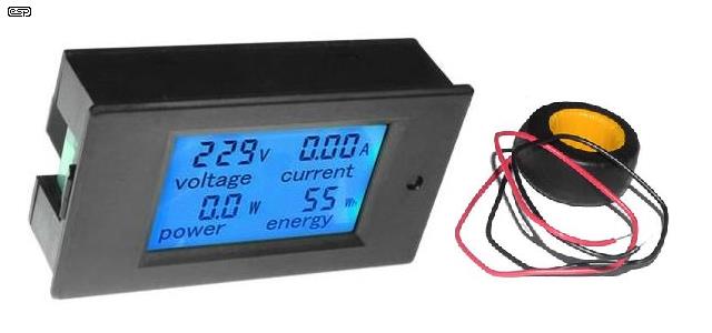
Now, complete wattmeter modules are available for very little - some are less than US$10.00 which means that anyone who wants to know the power drawn by anything in the lab or the home can do so easily. It's simply a matter of wiring it into a box and connecting mains inputs and outputs. The unit pictured below is rated to operate from 80 to 260V at up to 100A, 50 or 60Hz. It's truly 'universal' in terms of operating range. To help you search, the brand name is 'peacefair', and not surprisingly, they are made in China.

Photo Of Wattmeter Module
The current transformer is seen in the photo, but it's not wired into the module. The 'Energy' part of the display isn't very useful for most applications, but it comes with the unit. The current transformer is one of the most important parts, as it detects the current flowing through the wire that passes through the centre, and allows accurate computation of the true RMS current and power (watts). You can calculate the apparent power (in VA) by multiplying the voltage and current readings together.
If you are unsure about the difference between true and apparent power (watts and volt-amps or VA), please see the article Power Factor - Reality which explains it in some detail (also in the 'Lamps and Energy' section).

Internal Photo Of Wattmeter Module
The insides are shown above. The processor (?) is unknown because the number has been erased, but the larger of the other two ICs you can see is a TM1621 LCD driver. The other (next to the 6MHz crystal) is an HT7017 which is apparently a 'high precision single-phase metering chip'. Unfortunately, the only datasheet I could find for either IC was in Chinese, but the metering chip appears to perform all calculations required to obtain RMS volts and amps, as well as power. From what I could gather, the metering IC is 22 bit, and accepts input values of ±800mV about the internal 2.5V reference. This info isn't necessary to know to be able to use the module, but where's the fun if I didn't have a look inside?

Note: The large red capacitor seen in the photo is a standard 400V DC device, and it should be replaced with an X-Class (275V AC) type. DC Capacitors will fail if used with 230V AC. The original cap was no doubt selected because it's somewhat cheaper than an X-Class cap, but it won't last very long due to the high voltage across it. In 120V countries it will probably be alright, but not with 230V. The original cap is a 1.5µF 400V DC type. Replace it with a 1.5µF 275V AC Class X2 cap. Cut off the leads right at the cap itself, and solder the replacement to the remaining leads. You don't need to remove the PCB.
This is an unusual project for ESP, in that you really don't get to build much for yourself. However, when I bought of one of the modules described (I couldn't resist  ), it was immediately apparent that it would make an excellent little project, because it gives you a useful tool for a very small outlay in time, parts and money.
As noted above, if your mains is (nominally) 230V, replace the red capacitor with an X2 class (275V AC) unit to minimise the risk of failure. Do this before you wire everything up. The rear cover is held in place with 4 plastic clips, and it's easy to remove. The 400V DC capacitor supplied as standard can be retained if you are in a region where the mains is 120V (if you wish).
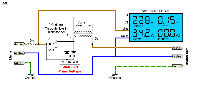
As shown below, the unit is given two current ranges - x1 and x10. By winding 10 turns through the current transformer, we can measure current below 100mA with higher accuracy. This is optional of course, but it makes the unit more useful as a piece of test gear. The x10 range will allow measurements down to 10mA (2.3VA or watts), but it will not be with great accuracy at such low currents. When the current range is set to x10, the power range is also x10, so a reading of 23W actually means 2.3W.
If you don't require the increased sensitivity which will (at least in theory) allow you to measure down to less than 100mW, you simply wire the unit according to the diagram on the back of the module [ 1 ]. However, while this might be fine for normal household usage, it's not good enough if you wish to measure low power electronics, small 'plug pack' (aka wall wart) switchmode supplies, or other low power devices.
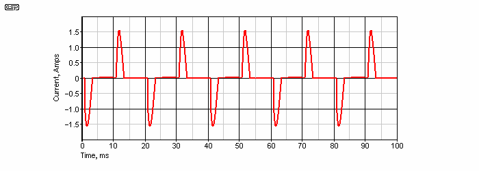
Many products draw a very nonlinear current from the mains, and this is not always measured as accurately as you might hope for. The nonlinear waveform has to go through some computation to derive the true RMS value, and in some cases the waveform can be so spiky that it clips the A-D converter. This can happen with any power meter, and is something that you need to be careful with when you take a measurement. The next figure shows a simulated current drawn by a typical mains rectifier followed by a capacitor. While the drawing is a simulation, reality is usually very similar.

Figure 1 - Typical Nonlinear Waveform
Even though the peak current is over 1.56A, the RMS current is 552mA, corresponding to 128VA. The crest factor (the ratio of peak to RMS) is less than three, and most RMS converters and true RMS meters can handle crest factors of up to five before accuracy is compromised (i.e. the peak current is 5 times the RMS value). This varies with the meter of course, but if it's computed rather than processed with a 'true RMS' converter IC such as the AD737 (as described in Project 140), the allowable crest factor may be higher than may otherwise be the case.
The power for the above waveform (at 230V RMS) is 74 watts, so the power factor is 0.58. This is simply calculated by dividing the actual power (in watts) by the apparent power (in VA). This is why you need a wattmeter - if you simply measure the current with a true RMS meter and work out what you think is the power, you are calculating VA, not watts. With the wattmeter, you can measure the true power of nonlinear or reactive loads, and determine the power factor (PF) by working out the VA (volts x amps) ...
VA = Volts x Amps
PF = Watts / VA
This calculation works with all loads, provided the meter can calculate the true RMS value properly. The unit shown here seems to be fairly good in this respect, but of course it's not possible to verify that it will give the right answer with all loads. To some extent, we have to accept that the makers of any metering equipment will have done their maths properly so we get the right answers. This applies even with expensive true RMS multimeters - very spiky waveforms (similar to the above but with higher and narrower spikes) can give errors with even the very best meters.

Figure 2 - Wiring Scheme For The Wattmeter Module
You might be wondering about the two diodes. Good question, even if you didn't ask  . When the switch is changed from the x1 to x10 range or vice versa, there's a very brief period where the AC is effectively disconnected as the switch contacts open before closing the other connection. This will annoy some electronics, with medium to large toroidal transformers being the most likely to be unhappy. The diodes maintain (almost) the full mains voltage during the brief changeover period, so there's no interruption. The two windings have very low resistance because they are only 1 turn or 10 turns of mains rated cable. This means that there will be a few millivolts at most across the diodes, so they have no effect on the current reading. You can use two sets of diodes in series if you prefer, but it's unlikely to make any difference.
Otherwise, the circuit is virtually identical to that shown on the back of the wattmeter module, except a fuse has been added. This is optional, but having some form of over-current protection is always a good idea. You can use a circuit breaker if you have one handy and prefer that option. If you use a fused IEC connector for the mains input, there's no additional hardware needed.
All mains connections should be protected with heatshrink tubing, including the diodes. If you don't have 1N5404 diodes or similar, you can use four 1N4004 in parallel (with two reversed of course). They will conduct only during the brief period when the switch contacts are changing state, so won't be stressed even with loads well over 5A or so. Note that the switch must be a full size toggle switch, rated for mains operation. Do not use miniature toggle switches for mains, as their insulation, creepage and clearance distances are inadequate to ensure safety.

Warning: Under no circumstances should the current transformer be operated without either being connected to the wattmeter or having the leads shorted. Very high voltages can be developed by any current transformer with no load (the load is technically known as a 'burden'). For more information about how current transformers work, see the section on current transformers in the Transformers - Part 2 article.
Note that the current transformer's output must not be made available as a current monitor (as described in Project 139a) because it is not isolated from the mains! If you need a current monitor for your oscilloscope, you must use another current transformer. There is no measurable loss of mains voltage through the current transformer(s), so using two will not cause problems.
Be careful when using the meter on the x10 range. When you connect your load, the switch should always be in the x1 position until you verify that the current is less than 1A. Then you can change to the x10 range to get better resolution. The degree of protection in the unit is not known, but it is rated for up to 100A (99.9A to be exact) and most loads will be much less than the maximum. Transformer or SMPS inrush current can be very high though, so using the x1 range at power-on is safer for the wattmeter. This also gives you an indication if the current waveform is causing problems. If the meter shows (say) 300mA with switch set to x1, but does not show 3.00A set to x10, the waveform may be causing overload on peaks.
The hardest part of this project will be waiting for the wattmeter to arrive (postage from China can be pretty slow), followed by deciding on a suitable case. The wiring is straightforward, and should cause little or no grief. Do be careful to ensure that the 10 turn winding actually passes through the centre of the core exactly 10 times, or the x10 range will be inaccurate. The windings don't need to be especially neat, and what happens outside the core is of no consequence. The single turn only has to pass through the centre - it doesn't have to make a complete turn around the core.
The wiring from the current transformer is not polarised - the measurement IC in the module works out the correct polarity as part of its internal processing. The tests I've run so far indicate that it's fairly accurate, and the measurements will be more than good enough for most typical bench work. It's doubtful if the energy reading would be up to the standards of your utility supplied kWh meter in the switchboard, but that's secondary to the ability to monitor voltage, current and power.
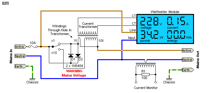
A modification that I added to my wattmeter was an additional current transformer. The secondary is terminated by a 100 ohm resistor, and the connections are wired to sockets on the front panel. This lets me see the current waveform on an oscilloscope, and if the voltage is increased gradually with a Variac, I can see instantly if there is a problem, well before the wattmeter circuit is able to run due to the reduced voltage. Small current transformers are available from ebay for not much over $1 each, but despite the cost they work very well. Electrical safety is not compromised because the CT is not electrically connected to anything - its output is totally isolated. Of course, this does demand that you take appropriate care with wiring, and keep the low voltage CT output wires separated from all mains wiring.

Figure 3 - Wiring Scheme For The Wattmeter Module With Added Current Transformer
With a pair of banana sockets (or any other type that you may prefer), you can examine the current waveform and its magnitude. Note that you MUST use a second current transformer. The CT used for the wattmeter is dedicated to that purpose, and its secondary terminals will be connected to the internal circuitry which is live! There is no isolation, but by including the extra CT you get a safe and easy way to monitor the current waveform. The second CT can be in the active or neutral, and either works identically. The output is 100mV/ Amp, so if you measure 150mV peak (with any waveform), the peak current is 1.5 amps.
This arrangement gives you the best of both the basic project described here, as well as a simplified version of Project 139A. If there is enough space in your case, the complete P139A circuit can be included, with the option of 100mV/ amp and 1V/ amp. I still use my current monitor regularly, but the added current transformer just makes the wattmeter so much more useful than it was before the extra CT was added.
Not everyone will want or need a 'proper' wattmeter, but something along the same lines as this (although the actual module may be different) are very useful if you need to know the true power drawn by your latest electronics project. Naturally, it can also be used to test appliances or even monitor the total power used by something (the energy field is non-volatile, and is retained when power is removed).
For the cost (peanuts), it's hard to do better, and the separate current transformer gives you the option of increasing resolution 10-fold. You can't do that with other plug-in wattmeters because they are all sealed and some may not even use a current transformer. Current can be measured several ways, including reading the voltage developed across a low value resistor. You still get the right answer, but it's much harder to modify, and the accuracy is likely to be lower than units such as the one shown here.
You also get the satisfaction of building it (well, part of it anyway) yourself, so the input and output mains connections can be tailored to your needs. It can even be permanently wired into your test bench, so you have a useful current monitor as well as a wattmeter ready for you to plug anything under test into so you can get accurate readings of its power and power factor. This ability was limited to professional laboratories with good budgets up until fairly recently.
While this doesn't qualify as (and is not intended to be) a piece of 'super-accurate' laboratory equipment, it will still provide readings that are more than acceptable for the purpose, and it will be a useful piece of test gear in any workshop. The fact that the entire project will probably cost you less than AU$30.00 means that you get the ability to take real power measurements for next to nothing, and you also have a handy current monitor that will show you instantly if a project or repair job is drawing more current than it should, indicating a fault.
By adding the extra current transformer, you have an even more useful project, and you can see if there's a problem with the connected equipment well before the wattmeter has enough voltage to operate. This assumes the use of a Variac, which is without doubt one of the essentials of a well equipped workshop.
This application can be especially useful when working on power amps as it shows if there is a thermal runaway condition (the idle current will start rising and doesn't stop). It's also handy when working on valve power amps, guitar amps, etc. Tests can be carried out without even taking off the covers, and when you know what to expect, if you see something different you know there's a problem.
Please note that this article is not a specific endorsement for the module shown, and there are others that will no doubt be suitable as well. The choice of wattmeter module used is up to the constructor, and ebay usually has several to choose from. Some may not be supplied for very long. Supply is often patchy at best, so you may need to use something different based on what's available. It's important that it includes the current transformer - most do, but that may change in time. Note that I can make no comment one way or another about long-term reliability of the wattmeter module, as I haven't had it long enough yet.
There are other (very similar) units that use a current transformer that can be opened to allow it to be placed over an existing wire, then closed again. I suggest that you do not use one of these if there's a choice, because the transformer may not be accurate or completely predictable due to small air gaps between the magnetic cores when closed. A 'fixed' toroidal transformer is always preferable if possible.
Note: Be very careful when purchasing - there are wattmeters that look almost identical, but they are for DC, not AC. A low voltage DC meter is obviously unusable for this application !
 Main Index
 Projects Index
| Copyright Notice.This article, including but not limited to all text and diagrams, is the intellectual property of Rod Elliott, and is © 2017. Reproduction or re-publication by any means whatsoever, whether electronic, mechanical or electro-mechanical, is strictly prohibited under International Copyright laws. The author (Rod Elliott) grants the reader the right to use this information for personal use only, and further allows that one (1) copy may be made for reference while constructing the project. Commercial use is prohibited without express written authorisation from Rod Elliott. |