
|
|
| Elliott Sound Products | Satellite Loudspeaker (1) |
 Main Index
Articles Index
Main Index
Articles Index
This is a small satellite speaker system that puts together speaker design ideas found in several ESP articles. It stems from the need to get the most high quality sound from the least space, and to have the "big speaker" effortless sound quality in a small package.
As mentioned in the QB5 article [1], a good way to start is to ensure that the drivers always operate within their linear cone excursion up to the peak output required.
The speaker system accordingly has a QB5 II alignment using the "small front speaker" output of a 5.1 receiver as a high pass filter, and also has a waveguide tweeter for directivity control and increased power handling.
Since the lower cut off for non-THX receivers is generally in the 100Hz region, several examples in a range of good quality nominally five inch driver can, with a QB5 II alignment, go down to 100Hz and produce peak outputs of 110dB for the pair without exceeding their linear excursion limit (although not by much in some cases).
These drivers generally need a box of around 8-9litres in this application. Looking at good quality drivers from several manufactures the one that stands out as suitable for our purpose is the Peerless 850488, and the tweeter originally chosen was the (now discontinued) Vifa D19-05-06, as the 1700Hz resonant frequency of this would allow the use of a third and fourth order quasi Linkwitz Riley crossover described by Leach [3].
The 850488 is chosen over its more expensive phase plugged cousin the 850489, because it has better second roll off characteristics, potentially allowing the use of a second order filter to obtain an overall fourth order characteristic. From the frequency response data, a notch filter may well be needed for the phase plugged driver.
The 850488 driver has been discontinued and the 830860 is recommended as a replacement As it turns out the 830860 driver also needs more complex crossover. It also has inferior excursion limited power handling down to its cut off frequency, this is illustrated in the win ISD plots of figure 1 ...
Figure 1 - WinISD Plot of Maximum Excursion Limited Power Handling
Both drivers have a similar cut lower off frequency and are mounted in an 8 litre box and fed from a second order Butterworth filter at 100Hz. As can be seen the 850488 driver has better power handling and is capable of more SPL before excursion limiting.
The measured frequency response of the driver is shown in figure 2 ...
Figure 2 - Measured Frequency Response of 830860 Driver
As can be seen, the driver has a response peak at 5kHz. This peak does not appear on the manufacturers published frequency response chart.
Figure 3 - Driver With Linkwitz-Riley Crossover Simulation
The effect of using a Linkwitz-Riley filter on this driver is illustrated in figure 3. As can be seen the frequency and phase response of this combination falls far short of the ideal L-R characteristic. The actual roll off does not occur until the drivers second roll off peak, and the phase characteristics are not all pass.
Luckily there is something we can do about this, and that is to use one of the notched low pass filters described by Thiele [4]. This has been modified to include a damping resistor (see figure 4), and illustrates the type of response we can expect from this, with a Q=5.
Figure 4 - 830860 Driver With Notched Crossover Simulation
Overall the rolloff and phase response follows the L-R curve more accurately than figure 3. Although the response again departs from the ideal, the above is a better match to the ideal L-R, and to get it significantly better increases the coil count.
In the notched crossover chosen the notch is put at the 5kHz peak in the driver response and the nominal roll off frequency is 3kHz.
Figure 5 - Notched Low Pass Filter Arrangement
An advantage of the notched type of crossover is that it swamps the out of band characteristics of the drivers. It leaves the crossover region close to an ideal L-R all pass characteristic even if significant deviations (such as a second roll off peak), are in evidence. In this case for instance, the woofer has a second roll off Q of around 2, and the tweeter has a smooth lower roll off with a Q in the 0.7 region and yet we can get good phase characteristics through the crossover region leading to good lobing performance. (The final crossover is shown in figure 9.)
Figure 6 - Measured Frequency Response of 830860 Driver With Notched Crossover
(Blue = 27 Ohm resistor, Green = no resistor)
Figure 6 shows the measured response of the driver plus crossover. The notched "NTM" (Neville Thiele Method) fourth order filter can be seen as a resonant trap cascaded with a second order low pass section. The filter characteristics can be modified by the inclusion of a damping resistor, and this provides a simple means of fine tuning the crossover.
I looked at several types of tweeter including Vifa 20mm soft dome types. One difficulty with the Vifa 20mm soft dome tweeter is that it has the diaphragm and coil assembly mounted directly to the front plate and this presents difficulties in fitting a waveguide, and the frequency response down to 3kHz is not especially good. Apart from any of this, the aluminium dome 20mm tweeter sounds better.
Having a pair of the trusty (but now discontinued) D25AG tweeters on hand I pressed these into service, mounted on the waveguide shown below.
Figure 7 - Tweeter Waveguide
This waveguide is formed directly in the baffle and is of the three section sort described in the waveguide article [5]. Using this waveguide in conjunction with the mounting ring brings the acoustic centers of the drivers to within a few millimeters of each other.
Figure 8 - Acoustic Offset of Drivers
The use of a notched response low pass section makes a notched high pass section virtually mandatory, leading to a four coil crossover.
Figure 9 - Final Crossover Circuit
The frequency response of the prototype of this crossover is shown in figure 10.
Figure 10 - Frequency Response of System With Illustrated Crossover
As can be seen the response is within +- 2dB in the 1k-15kHz region. At this stage the reflex box is not in operation, hence the limited frequency range.
Figure 11 - System Impedance
The impedance shows a relatively smooth curve, peaking at 8.4 ohms in the 2kHz region and dipping to a low of 3.9 ohms at 20kHz. The overall impedance can be rated at 6 Ohms, and is compatible with 5.1 receivers rated for 6 Ohms.
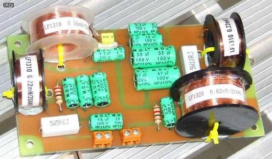
Figure 12 - Completed Crossover Board
The crossover system is built upon a 75 x 150mm piece of PC board, and attached to the inside of the removable section of the back panel. As can be seen, the capacitors are mostly the bipolar electrolytic type, as there is little room for anything else. Despite all of the hype to the contrary you really can't hear them.
Those who look up Thiele's original paper will note that the actual component values differ from those indicated there. This is because the parameters have been adjusted so that standard value inductors can be used, (I am far to lazy to wind my own), and the values shown maintain a close approximation to an all pass characteristic when the driver transfer functions are taken into account.
Main Index
Articles Index