
|
|
| Elliott Sound Products | Volume Filling a Reflex Box |
 )
) Main Index
Articles Index
Main Index
Articles Index
Attenuating rear output (removing 'boxiness') has become increasingly important, because the satellite plus subwoofer speaker system has now become almost universal for home theatre applications. The article about QB5 alignments illustrates a way of overcoming a basic limitation of this scheme, that is if a simple two way satellite is used getting satisfactory output down to 80-100Hz with a typical 125 - 165mm (5 - 6.5 inch) driver can be a problem without a filter assisted reflex alignment.
Another problem that exists is that since the low frequency driver is required to operate over an approx. 80-3kHz band, rear radiation reflecting back through the cone becomes an issue, and the sealed box solution of volume filling presents potential problems with reflex loading.
What follows is a discussion about this problem, and some measurements of a box stuffing scheme intended specifically for bass reflex (i.e. vented) loudspeakers.
The chart of Figure 1 indicates the sort of attenuation we can expect from the usual 25mm lining, as recommended for most bass reflex projects.
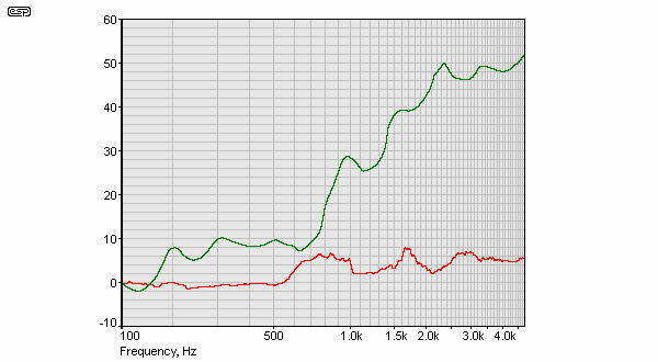
Figure 1 - Attenuation of Back Radiation
The above shows reflection, (red), and absorption (green) of 50mm polyester, approximately 25kg/m³. The peaks at 1 and 2kHz are due to standing waves in the test fixture. As can be seen the polyester fibre does not start to provide any really useful attenuation until around 1kHz, and then over the range we want we can expect no more than 10-15 dB with a typical 25mm covering at the standard density.
Figure 2 shows the attenuation per metre we can expect from glass fibre two packing densities. (From, Bradbury, [ 1 ], p. 407)
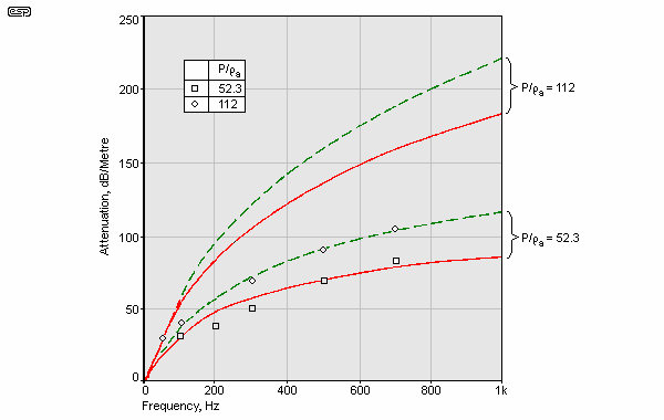
Figure 2 - Variation of Attenuation with Packing Density
Volume filling of a reflex enclosure can present a potential problem because the filling acts to decrease the effective port Q and reduce its output by increasing the loss resistance [ 3 ]. As an example using the boxnotes download [ 4 ], the resonances inside a 10 litre 167 x 267 x 200mm box are ...
With an average path length reflected back to the driver cone of 0.802 metres, and using 150dB per metre we can, on average, attenuate the rear radiation by 128dB by this calculation, a compelling reason to volume fill the box. A difficulty we face is that this is a high density (100 + kg/m³) of filling and the vent resistance might well be high enough to severely attenuate the port output.
Filling attenuation characteristics are greatly affected by the diameter of the constituent fibres, smaller diameter fibres have attenuation that rises more steeply at the high frequency end than do larger diameter fibres. (From Bradbury, [ 1 ], p. 408.)
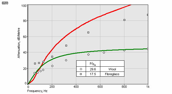
Figure 3 - Variation in Attenuation with Fibre Diameter
(Wool, d = 0.028mm P = 35kg/m³, Glass Fibre, d = 0.005mm, P = 21kg/m³)
Bradbury's data indicate that in the range 50-150Hz the resistive part of the impedance is the same for the packing density of 9 for glass fibre with a diameter of 0.005mm, and wool with a diameter of 0.028mm, but at higher frequencies the attenuation provided by the smaller fibre diameter increases more rapidly and the attenuation for the same packing density is more than twice as much. (From Bradbury, [ 1 ], p. 410).
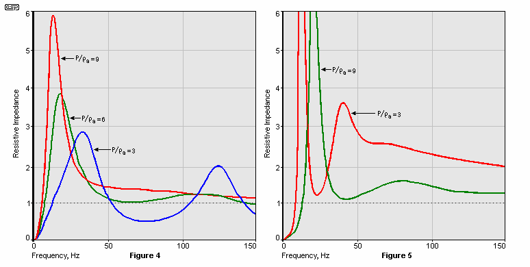
Figures 4, 5 - Wool Filled (left), and Fibreglass Filled Pipes
From the above, if we can keep the attenuation parameter high at high frequencies by making the fibre diameter smaller, we can keep attenuation at low frequencies small enough to potentially not unduly affect Qb, and yet provide useful attenuation at higher frequencies.
If we provide a filling with an average of 50 - 60dB per metre in the region of the most common resonances, then the path length is 0.66m and the attenuation = 33 - 40dB plus a potential 12 - 15dB at the surface, and this is the aim point for what follows.
The product sold at local electronics retailers as a substance for stuffing boxes, (tested in Figure 1), is a polyester fibre material with a round fibre of around 0.01mm diameter and has a density of around 25kg/m³. From Bradbury's data, teasing this out to half its standard density should be about what is needed for volume filling the reflex box.
The enclosure losses caused by volume filling are manifested by the Q of the vent output. Tables such as those by Bywater and Wiebl use a Ql value of 7, the QB5 tables use 5. The leakage Q is the largest loss in the system and it is usual to assume that Qb = Ql. In the following experiments the technique of measuring the vent Q with no box stuffing, and then with a low density volume filling scheme is used, a Ql = 5 is acceptable.
The following tests were carried out on a 8 litre box tuned with an exaggerated peak, and will investigate the internal reflections present in various cases.
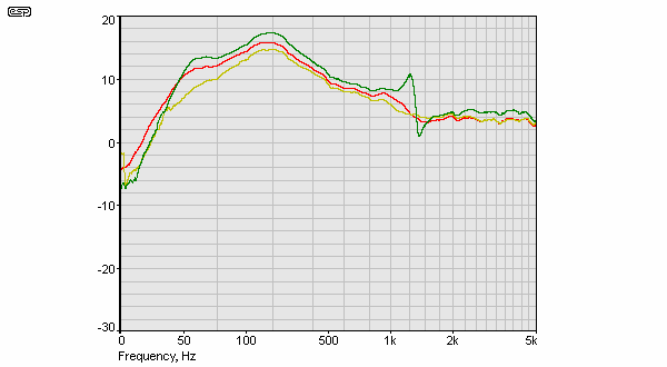
Figure 6 - Combined Vent and Driver Output
No stuffing, (green), 25mm wall covering, (red), plus 12kg./m³ volume filling, (yellow)
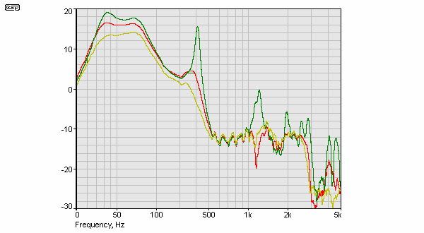
Figure 7 - Vent Output
No stuffing, (green), 25mm wall covering, (red), plus 12kg./m³ volume filling, (yellow)
From this the port output is attenuated by 3-4dB. The efficacy of a sound absorption material can be defined as its ratio of reflection to absorption.
4 × z1 × z2 / ( z1 + z2 )² is the transmitted sound
(z1 - z2 / z1 + z2 )² is the reflected sound
The standard method of measuring absorption reflection is a Kundt tube [ 5 ] or reverberation chamber [ 3 ], since I don't possess either one I put together a rig that does give some indication of the properties of several materials.
The speaker workshop software allows the signal processing operations of convolution and deconvolution to be done, this allows us to get reasonably good results with very basic equipment, this device is made from scrap bits of MDF and particle board and sealed with 'Blu-Tac' or similar.
The test cell is fitted over a 140mm (5.5 inch) driver in a speaker box. It is proportioned so that the test piece can be 90mm in diameter and 50mm deep, and the overall performance is reasonably accurate up to 5kHz.
Several data sets are then recorded with the sample in place and not, and the cell open and closed. By convolving and deconvolving the various data sets it is possible to measure the absorption and reflection coefficients of the sample in the cell, the chart of Figure 1 was obtained in this way.
The input signal is a 10ms pulse and four measurements are taken, cell open and closed with and without sample in place. The FFT is then calculated and the 'cell open' / 'cell open with sample' deconvolved, giving the reflected signal. The same is done with the 'cell closed' / 'cell closed with sample' to give the absorption.
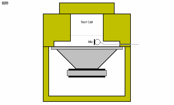
Figure 8 - Acoustic Absorption/Reflection Test Fixture
These tests are of a 38mm thick acoustic foam tile with an anechoic wedge pattern, available at local electronics chains (in Australia).
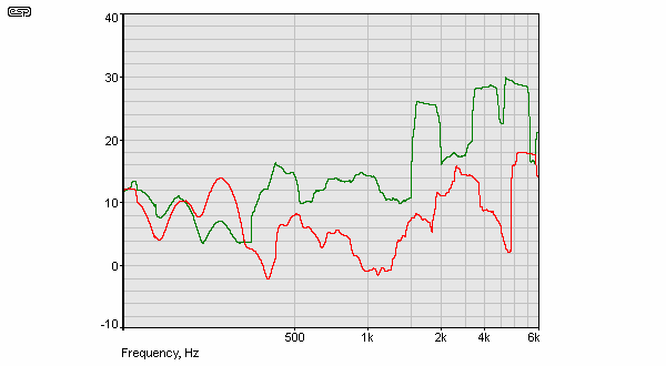
Figure 9 - Absorption, (green) and Reflection of 38mm Acoustic Foam Tile
The plot shows a very rough trace, with reflection exceeding absorption at a few hundred Hz. From this test the polyester fibre material is to be preferred.
Tests were conducted with a box lined with the acoustic tiles and volume filled with the fibre material.
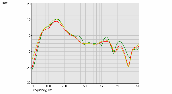
Figure 10 - Combined Output
Foam and Poly (yellow), Foam Only, (red), Empty (green)
The overall output is noticeably smoother with both foam and polyester fibre (or foam only) in place. The box Q seems relatively unaffected.
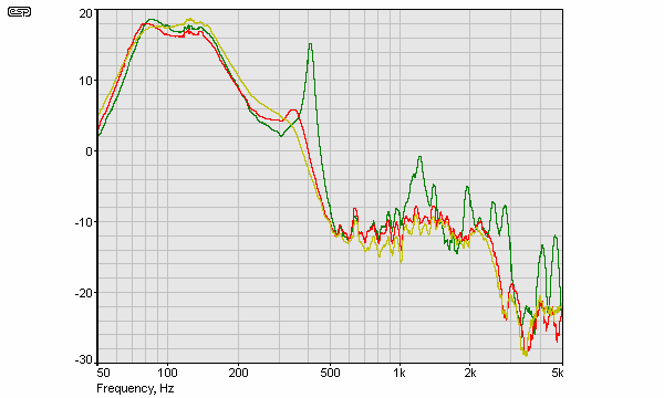
Figure 11 - Port Output
Foam and poly (yellow), Foam only (red), Empty (green)
Prominent resonances apparent in the no stuffing case are removed by stuffing.
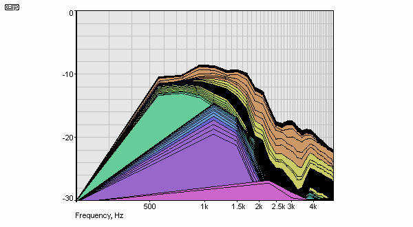
Figure 12 - Waterfall Plot of Empty Box
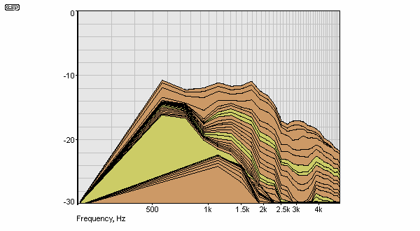
Figure 13 - Fibre Fill Only
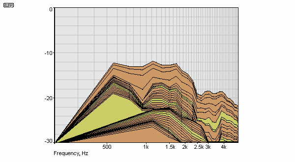
Figure 14 - Fibre Fill + Wall Covering
The waterfall plots were prepared by Fourier Transforming the near-field data set and restricting the time window to 3ms to avoid room and nearby object interference. The foam wall covering results in a generally faster and smoother decay spectrum especially at the lower frequencies, and less vent output attenuation. The inferior test cell result is clearly due to anomalies in the test apparatus.
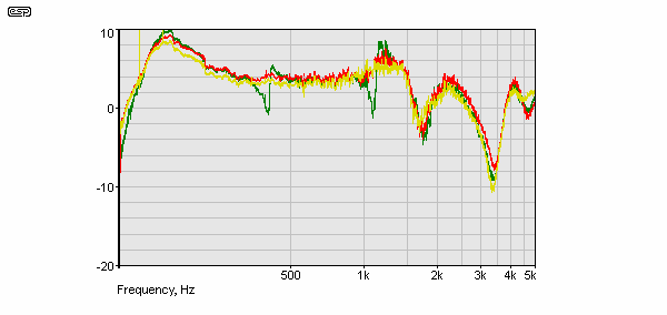
Figure 15 - Un-smoothed Near-Field Frequency Response
Box empty (green), All fibre (red), Fibre plus foam (yellow)
While in no way claiming these tests to be definitive, it does appear that a reflex box can be filled by a medium density fibrous material and that it is beneficial to cover the inner surfaces with acoustic foam. The effect upon the box Q is minimal and the re-radiation through the cone and the port is reduced significantly.
The above article covers many of the things that I had actually intended to write about (at some stage, when I had the time). As most longer term readers will know, I'm not very fond of small reflex boxes, but I do have a pair set up in one of my rooms. The boxiness Robert refers to at the beginning of the article was immediately apparent, and was solved by adding fibreglass to the boxes. This wasn't done using any scientific methodology - I simply guessed at what seemed like a reasonable amount and used that.
This cured the worst of the problems, but since the speakers concerned are only a temporary affair (and have been for over a year at the time of writing) I wasn't too concerned about trying to get them perfect. They will be replaced at some point, and the techniques discussed will be used with a great deal more diligence to get the best possible sound quality ... tempered by the fact that they will never be expected to replace my main system.
There is no doubt that many 2-way speakers suffer from similar problems. It is very common to find enclosures that will have obvious resonances - including some designed by respected loudspeaker designers. Exactly as Robert describes here, one design in particular used an open cell foam to line the interior walls. Although the designer swears by it, the foam is completely useless for damping the various resonant frequencies in the box. Adding fibreglass in these enclosures disturbed the bass to some degree, but the midrange was so much cleaner that it was well worth the small sacrifice.
I can think of several additional methods that will help break up internal standing waves - a brace behind the mid-bass driver, suitably angled and wide enough to catch (and deflect) most of the rear radiation is one method. Use of non-parallel sides is often used and will also reduce (perhaps dramatically) the standing waves in the box. Combining these techniques should enable one to build a small vented loudspeaker that has almost no bad habits, depending on driver quality of course.
In summary, there is no reason that a small system should sound boxy - it will lack deep bass, but that's inevitable with a small driver in a small enclosure. If the system can be made to sound as good as possible, one is far more likely to listen to it. Listener fatigue is common with smaller systems because of exactly the effects described. By eliminating the problems that cause listener fatigue in the first place, even small systems can give a very satisfying experience.
Naturally, adding a subwoofer to accommodate the deep bass will fill in the missing bottom octaves. If it is well integrated, its contribution will seem to be coming from the satellite speakers, with nothing to give away the sub's location. This is an eerie sensation at first, and if visitors ask how you can get such deep bass from such small speakers, you know that the integration is a success  .
.
1 - L J S Bradbury, "The use of Fibrous Materials in Loudspeaker Enclosures", AES Journal, Vol. 24, No. 3, (April 1976)
2 - R H Small, "Vented-Box Loudspeaker systems part IV: Appendices", AES Journal, Vol. 21, No. 8, (October 1973).
3 - D A Russell, "Absorption coefficients and impedance", G.M.I. Engineering & Management Institute Download
4 - Hyperphysics - Longitudinal Waves - Kundt's Tube
5 - Bill Collison, Boxnotes
Main Index
Articles Index