

|
| Elliott Sound Products | Satellite Loudspeaker (3) |
 Main Index
 Articles Index
After having built a loudspeaker, it is always good to measure the final result to ensure that it meets the design criteria. This also allows any small anomalies to be ironed out. It is the nature of loudspeakers that all the theory in the world doesn't guarantee a good outcome, and that the end result can always be tweaked to make it better. The trick is knowing when to stop - one could spend a lifetime trying to get that last 5% of a system just so. Fortunately, this usually isn't necessary as the test results show.
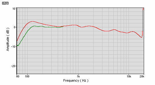
Figure 18 - Frequency Response With No Filter (Red),
and 5.1 Receiver Speakers Set to "Small Front" (Green)
The above shows curves which are a close approach to those that we would expect for an ideal QB5 II characteristic and should ensure worthwhile improvement in excursion limited power handling. It is important with small systems that we should not expect them to be able to match much larger systems. The laws of physics ultimately dictate what can be achieved, and the system described comes very close to the limits of what can be done with the drivers used.
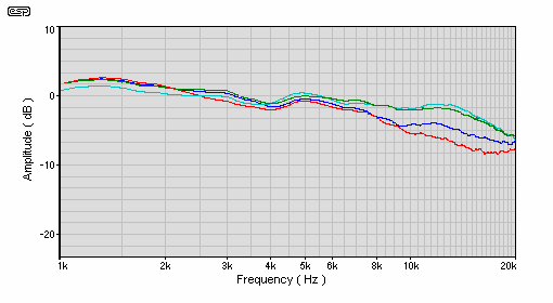
Figure 19 - Horizontal Directivity, On Axis, 15°, 30°, and 45° Off Axis
The directivity curves show very smooth response with constant directivity being maintained up to the highest frequencies. This is a very good result, and is largely because of the waveguide.
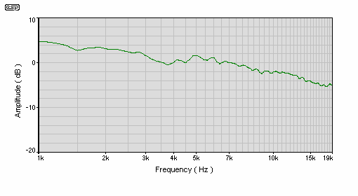
Figure 20 - Power Response of Speaker System
Above is the combination of the off axis response data, giving an indication of the system's actual power spectrum in a room.
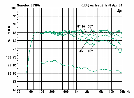
Figure 21 - Directivity and Power response of Genelec 8030A From Published Data Sheet
For comparison, Figure 21 is from a Genelec data sheet for their 8030A bi-amped monitor. If anything, the curves are a bit smoother though the high frequencies suffer somewhat due to the larger tweeter (the Genelec uses a 20mm tweeter). The vertical axis directivity of the system described shows a large suck out at fifteen degrees in the 3-4kHz region and a lesser one at 30° off axis. Interestingly, Genelec do not publish vertical directivity data.
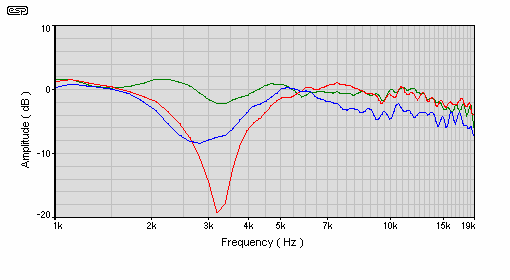
Figure 22 - Vertical Directivity, On Axis (Green), 15° Off Axis (Red), and 30° Off Axis (Blue)
Although the dip at around 3kHz looks bad, there is no alternative other than using a coaxial loudspeaker (which have their own unique problems). All speakers using separate midrange and tweeters have a very similar result, which is caused by phase cancellations. This is sometimes referred to as the "sit down, stand up" effect, where the tonal character varies according to your vertical position with respect to the drivers.
While steeper crossover slopes can reduce the width of the notch, its depth remains unchanged for a given angle. This is why speakers should always be installed so the tweeter is close to the same height as the listener's ears.
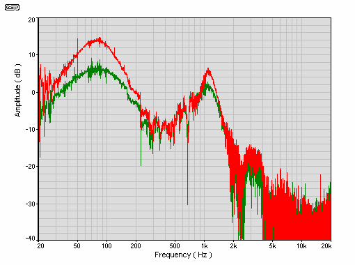
Figure 23 - Port With 12kg/m³ Polyester Stuffing (Green), and no Stuffing (Red)
Stuffing in the port was also tried. The result is considerable attenuation near the port resonance, but not really significant attenuation elsewhere. The enclosure depth gives phase cancellation of the port output in the 1 - 1.2kHz region.
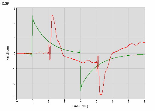
Figure 24 - 3ms Impulse Response (Red), Reference (Green)
It may look rather ragged, but the 3ms impulse response is excellent for a loudspeaker system. The square wave output is also very good, and is characteristic of loudspeaker systems with acoustically aligned drivers and a crossover with good all pass characteristics.
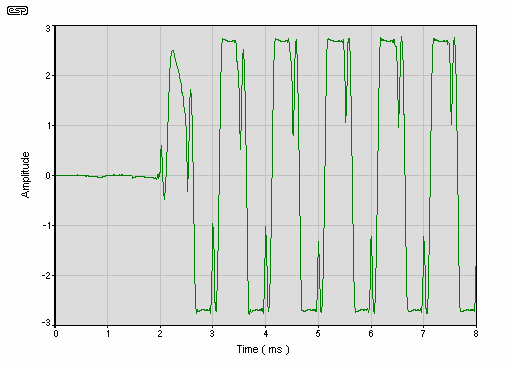
Figure 25 - 1kHz Squarewave Response
This a commercial unit made by Bowers and Wilkins that has had the built in pre amp bypassed because it has a fixed low pass filter. The frequency is too low for a 5.1 receiver. The small signal electronics were replaced by the circuit of Figure 21, housed in a separate box.
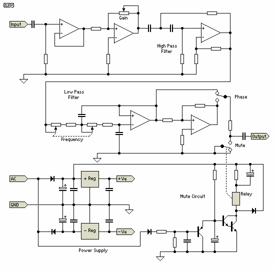
Figure 26 - Subwoofer Preamp Electronics
The sub electronics consist of an input buffer followed by a virtual earth variable gain stage. Next is a Q=2 high pass filter for the QB5 I alignment of the subwoofer, followed by a variable low pass filter and a phase change switch. The transistor circuit provides several seconds turn on mute plus very rapid turn off for shut down mute.
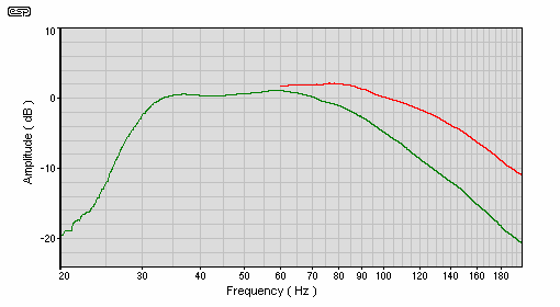
Figure 27 - Subwoofer Frequency Response with Described Electronics
Despite its second roll off peak necessitating a notched crossover system the 830860 driver has generally very good performance with low distortion and stored energy. Listening tests reveal that the system can be driven to high volume levels withought strain, and the overall sound is very neutral and accurate.
As readers of my articles well know, I would generally go for an active system. However, there are occasions where it is impractical, and this design is the result of just such an occasion. Few multi-channel amps have preamp-out, power-amp-in connectors, and modifications are often simply not possible. The PCBs are so closely packed that it can be very hard to even find the relevant sections in the circuit, and even if one does find them, there's no space on the back panel.
Modifications to the standard subwoofer electronics is almost mandatory. Of all those I've seen, the input stages are next to useless. Most have a peaking high pass filter, but no-one knows what driver or enclosure for which it is "optimised". In general, it is almost guaranteed that it will not match the requirements of the combination actually used.
Most high pass filters used feature a low frequency cutoff that is simply too high, but it can just as easily be too low for a small system. There is a good chance that the variable low pass filter will be misaligned (I've seen several that are), so have a "sloppy" rolloff curve. So, while commercially available "plate" amplifiers for subs seem like a good idea, the result is often disappointing unless the preamp electronics are bypassed or replaced. The enduring popularity of designs such as the P68 subwoofer amplifier is testimony to the fact that many people have realised that the commercial offerings are wanting if one expects decent performance.
The various cinema / home theatre formats don't help at all, as they have very limited functionality when it comes to the division of the sub and main speakers. This situation is so bad (IMO) that it is almost always better to use an external crossover, but again, without the pre-out & power-in connections this can be "challenging". Since almost all subwoofer plate amps offer only a variable low pass filter (with no high pass complement), the compromises can be far greater than expected.
Robert had to dispose of the entire sub amp's front end to get an acceptable result, and many others have found the same. As for the speaker level inputs, these are a complete waste of time and space. Since the "high pass filter" consists only of a bipolar electrolytic for each channel, the cutoff frequency is absolutely unpredictable. These inputs should never be used, because they cannot be relied upon to do anything even remotely useful.
A complete variable crossover system specifically for subwoofer use is currently in the works as a project. It will incorporate some very useful features that will completely replace the existing traditional subwoofer front-end found in plate amps. Unlike existing networks, it will include both high and low pass crossover filters, and can be used with mono or stereo subs. It is not intended to replace any of the existing projects, but does include the facilities that Robert used in the electronics described above.
 Main Index
 Articles Index