

|
| Elliott Sound Products | Satellite Loudspeaker (2) |
 Main Index
 Articles Index
The optimum satellite for this driver - as far as an optimum combination of size and power handling is concerned - has a 5.5 - 6 litre box, for an f3 of 100Hz. This is derived by the scaling the auxiliary filter damping method outlined in the compliance scaling article [5], we need to scale the filter Q down from 0.62 to 0.4
This system is however designed to be driven by a 5.1 receiver and the 0.4 Q filter that this alignment needs for a flat overall frequency response is not available, so the box has to be larger to accommodate the Q = 0.707 Butterworth filter at around 100-120Hz that is found in 5.1 receivers. This makes the total box volume around 8.7 liters - not much difference but if you are to accommodate 5-7 of them in a surround system, it can be significant.
The internal dimensions are 315mm x 154mm x 180mm ( H x W x D), and the relatively large depth is to accommodate a 58mm diameter x 120mm long rear mounted port. According to Bill Collison's calculator, this gives very low port noise up to the rated maximum output [6].
The final enclosure is a conventional rectangular box made from 16mm MDF, I used this because it is easily available from the local hardware store. Iverson [7] shows that with the largest panel length at 315mm we can expect a resonance at around 1.2kHz. The graph due to Small [8] shown in Figure 14 indicates the sound pressure at these frequencies will be very low.
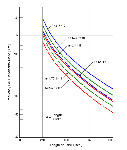
Figure 13 - Resonant Frequencies of Particle Board Panels
Although this data is for particle board, MDF has around the same panel resonant frequency.
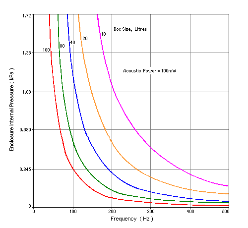
Figure 14 - Internal Sound Pressure vs. Volume and Frequency
On the subject of bracing, Iverson reports that the addition of a 50 x 25mm (2" x 1") pine brace on a panel 19mm thick and 405mm wide had the effect of moving the resonant frequency from 120Hz to around 140Hz, indicating that the panel stiffness is increased by only a modest amount, whereas the effect of all panels being joined solidly at the corners gives panel displacements that are comparable to that of a theoretically perfectly rigidly clamped panel. What this clearly means is that any bracing to be worthwhile must be very rigid, and there is a case recorded where bracing has actually increased resonance [9].
Iverson also measured a front panel with cut out moving from a resonance of 180Hz to 140Hz, and from this it is likely that the baffle has a resonance that is in a potentially troublesome region, so a stiff brace has been included that runs between the tweeter and woofer cutouts. In addition the woofer is mounted on a 4mm thick hardboard ring that is glued to the baffle (this also provides additional acoustic offset compensation).
The enclosure rear has a top panel 125mm high that is removable to make access to the inside possible. The bottom part is glued to the box, and includes the port.
Since the joining of the panels is so important to enclosure rigidity, these are joined with a rigid gap filling epoxy adhesive, and care is taken to ensure the joined surfaces touch over as much area as possible.
The importance of the rigid connection between the panel edges is illustrated by the fact that although the difference in resonant frequency between clamped and non clamped edges is very small, all rigidly clamped edges result in 3.8 times less deflection at the panel center, around - 11.5db.*
(* References about background information on these calculations appear in References section.)
A 16 x 30mm MDF brace placed on edge only decreases the deflection by about one third, and as illustrated by Iverson's data has no practical effect upon resonant frequency. Aluminium is however around 40 times stiffer than MDF, so using an extruded section as a brace offers potential.
Readily available at the local hardware store is aluminium extrusion of a 'U' section, 25mm on all sides and 3mm thick. This is suitable for stiffening the box since calculation indicates that across the 180mm side panels of the box, this section has about one eighth of the deflection the panel alone does for the same load. This should mean (although I haven't yet had the time to measure it), that putting a brace of this material in intimate contact with the panel (the large 25mm wide base of the section provides a large area for glue), should effectively break the panel into two panels and therefore push the panel resonance to around 4kHz - above the crossover frequency. As can be seen by Small's data, the internal sound pressure at this frequency is very low.
The bracing scheme is shown in Figure 16, and the fixed section of the back also has a brace across it.
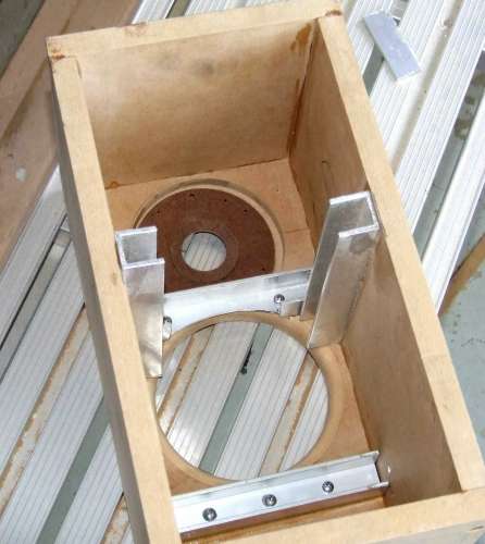
Figure 15 - Inside of Box with Bracing Installed
The final box is lined with 38mm. acoustic foam tiles and stuffed with polyester fibre at a density of around 12kg/m³, as described in the small satellite volume filling article, [10], found in the ESP articles section.
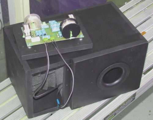
Figure 16 - Partially Assembled System Showing Removable Top Panel & Crossover Mounting
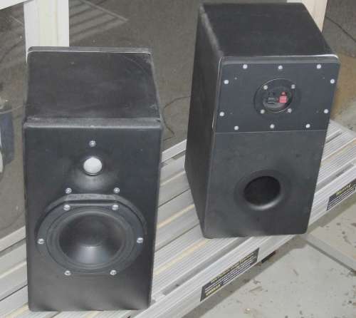
Figure 17 - Finished System
 Main Index
 Articles Index