

|
| Elliott Sound Products | Muting Circuits For Audio |
 Main Index Main Index
 Articles Index Articles Index
|
Providing the ability to mute an audio stream is both very common and in many cases, essential. I've described a remote receiver and transmitter that uses a relay for muting, and of all the methods available that is one of the simplest. The relay is wired so that the normally closed contacts simply short the signal to earth (ground). Until the relay is activated, the signal is muted, and because the contact resistance is typically only a few milliohms, there's no need to add resistance to the circuit that provides the audio signal (typically an opamp).
Most opamps are perfectly happy to have their outputs shorted, but as a matter of course I always include a 100 ohm output resistor to ensure stability if the opamp is connected to a reactive load such as a length of shielded cable. In the many years that I've been designing and building opamp and other 'small signal' circuits, I've never had one fail because its output was shorted.
The down side of using a relay is that muting (and un-muting) the signal is very abrupt, and while the difference between 'hard' and 'soft' muting is audible, most people are perfectly happy with relays for muting. Some people may not like the audible click made by a relay when it opens or closes, and others like the audible response. I like it because it provides audible feedback that the circuit is functioning, regardless of whether there's a signal or not. There are several other options for muting, as described below.
Mute circuits are also used at the inputs of many professional power amps. In some cases the signal is muted if the amp gets too hot, and nearly all mute the inputs for 1 - 5 seconds after power on. This is done so that turn-on/ off noises from mixers and other gear is blocked in case the entire system is powered up at once. There are countless applications for muting circuits, and not all are there so you can stop the noise from TV ads  .
.
One thing that is very important is that there must be no DC along with the signal that's being muted. Any single supply source (such as a USB DAC for example) must be capacitively coupled and have a bleed resistor to the signal common (earth/ ground) to ensure that the DC component is removed. Failure to do so may damage your loudspeakers, because the DC offset from some circuits can be quite high. If a mute circuit suddenly removes perhaps 700mV of signal along with 2.5V of DC, the noise will be very loud indeed!
One thing that really surprised me was the number of patents that cover perfectly ordinary muting circuits that have been used for years by any number of manufacturers. In general, these patents aren't likely to be worth the paper they are written on, because they are largely in the 'public domain'. It pretty much goes without saying that these patents have been granted in the US, where the patent system is often considered to be broken. It's hard to argue this, because there are so many patents that simply don't make any sense.
One form of muting that has been around for a very long time is used in FM receivers and other radio applications. When used with communications and CB ('citizens band') receivers, it's commonly called a 'squelch' circuit, and it's designed to mute the inter-channel noise. If no RF signal is received, you will normally hear white noise because the receiver operates at maximum gain and amplifies external noise as well as internal circuit noise. The muting circuit cuts out the background noise, but is released as soon as an RF signal is received.
Another form is called 'ducking', common in broadcast systems. If the announcer speaks while music is playing, the 'ducking' circuit partially mutes the music by reducing its level to some preset value that can be set with a pot. Some of the circuits below can be used to this end, by adding a variable resistance in series with the muting switch. The control and/ or level reduction circuitry is not described here because each case will be different. Ducking circuits will most commonly use a comparatively slow attack and release time so the effect is not abrupt, and an LED+LDR circuit is the most appropriate.
Of all the methods that can be used, this is my personal favourite. It's very reliable, and automatically mutes the signal when there is no power. To make the signal audible again, a transistor is turned on that energises the relay coil and removes the short. This can be done after a power-on delay, or at the touch of a button (local or remote). With a bit of extra circuitry, the mute can be reapplied at the instant power is turned off. This is provided for in the P05 preamp power supply for example, and it uses a 'loss-of-AC' detector circuit. The most common relay will be a miniature DPDT (double-pole, double-throw) type, and a single relay can mute both channels of a stereo preamp.
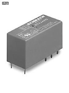
Naturally the relay has to be powered for as long as the signal is required. A typical small signal relay might draw around 12mA or so (assuming a 12V coil and a 1k coil resistance). The one pictured below has a coil resistance of 360Ω (12V coil) and will draw 33mA. There is some dissipation, but in real terms it's nothing to worry about with mains powered equipment. For battery operation it's another matter though, as every milliamp matters.
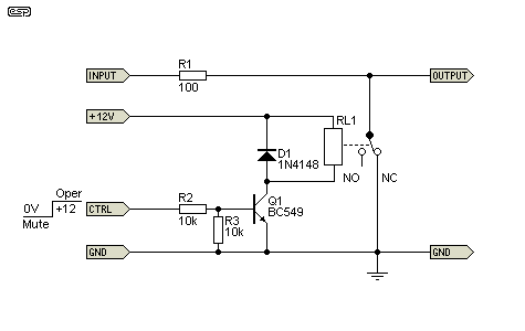
The input tagged 'CTRL' (control) activates the relay and removes the short with the application of a voltage from 5 to 12V. The attenuation of a relay is close to infinite because the contact resistance will be a few milliohms at the most. Because the normally open (NO) contacts are only used to short the signal to earth, there is zero signal degradation when the contacts are open. A relay also provides close to perfect protection for the output stage of any preamp, so stray static charges and other potentially damaging signals are simply shorted to earth and can do no harm.
The only down side of using a relay is that it usually does short the output of the preceding stage, although that can be solved if you are willing to pass the signal through the normally open contacts when the relay is activated (the output then connects to the 'NO' relay contacts). There are some circuits that may not be happy with a shorted output - discrete opamps and other all transistor circuits. Project 37 (DoZ Preamp) is one example, but provided the 100 ohm output resistor is included it's unlikely that it will come to any harm with normal signal levels (up to 3V RMS output). The easy way to ensure that it's happy at any level is to increase the output resistor to 560Ω. This is quite low enough for any preamp, and means that a shorted output cannot damage the preamp.
Relays are also ideal when balanced interconnections are used, as the relay contacts can simply short the 'hot' and 'cold' balanced signals together. Alternatively, a double pole relay can short both balanced signals to earth. Note that you absolutely must never short the two signal lines to earth when phantom power is used (either by design or accident). The method used depends on the application and the designer's preference.
Junction FETs (JFETs) can also be used, and like the relay they mute the signal by default. To un-mute the audio, a negative voltage is applied to the gate, turning off the JFET and removing the 'short' it creates. Unlike a relay, JFETs have significant resistance when turned on. The J11x series are often used as muting devices, and while certainly effective, the source impedance has to be higher than with a relay. The typical on-resistance (RDS-on) of a J111 is 30Ω (with 0V between gate and source). The J112 has an on-resistance of 50Ω, and the J113 is 100Ω (the latter is not recommended for muting). I tested a J109 (which is better than the others mentioned, but is now harder to get) with a 1k series resistor, and measured 44dB muting, and that's not good enough so two JFETs are needed as shown.
Note that JFETs will generally not be appropriate for partial muting (for a 'ducking' circuit for example), because when partially on they have significant distortion, unless the signal level is very low (no more than around 20mV), and/or distortion cancelling is applied. This application is not covered here.

To un-mute the signal, it's only necessary to apply a negative voltage to the gates. There is no current to speak of, and dissipation is negligible. JFETs are ideal for battery powered equipment, but there has to be enough available negative voltage to ensure that the JFET remains fully off ... over the full signal voltage range. If you use a J111 with a 10V peak audio signal, the negative gate voltage must be at least -20V (the 'worst-case' VGS (off) voltage is 10V), and the gate must not allow the JFET to turn on at any part of the input waveform.
Using a JFET to get a 'soft' muting characteristic works well. The JFET will distort the signal as it turns on or off, but if the fade-in and out is fairly fast (about 10ms as shown) the distortion will not be audible. You may be able to use a higher capacitance for a slower mute action, but you'll have to judge the result for yourself. I tested the circuit above (but using a single J109 FET) and the mute/ un-mute function is smooth (no clicks or pops) and no distortion is audible. Measured distortion when the signal is passed normally is the same as my oscillator's residual (0.02% THD).
If a JFET has an on-resistance of 30Ω, the maximum attenuation with a 2.2k source impedance is 37dB. This isn't enough, and you will need to use two JFETs as shown to get a high enough mute ratio. This is at the expense of total source resistance though. With the dual-stage circuit shown above, the mute level will be around -70dB. It is possible to reduce the value of the two resistors (to around 1kΩ) which will reduce the muted level to around -60dB, which is probably sufficient for most purposes.
You can improve the attenuation by applying a small positive signal to the gate, but it should not exceed around +400mV. Any more will pass DC through to the signal line as the (normally reverse-biased) gate diode conducts. In general I would not recommend this, as it adds more parts that have to be calculated for the mute control circuit, and the benefit isn't worth the extra trouble.
There is also the option of using a JFET based optocoupler (the datasheet calls it a 'symmetrical bilateral silicon photo detector') such as the H11F1. These are claimed to have high linearity, but I don't have any to test so can't comment either way. According to the datasheet, low distortion can only be assured at low signal voltages (less than 50mV). They might work as a muting device, but the FET is turned off by default, and turns on when current is applied to the internal LED. This means that the internal FET would need to be in series with the output for mute action when there's no DC present. The on resistance of the FET is 200Ω with a forward current of 16mA through the LED.
Analog Devices used to make ICs called the SSM2402 and SSM2412 that included a three JFET 'T' attenuator and a complete controller circuit for a two channel audio switching and/or muting circuit. They have been discontinued, and there doesn't appear to be a replacement. They were aimed at professional applications such as mixers and broadcast routing, and would be useful parts if still available.
It may seem unlikely, but ordinary bipolar junction transistors can be used for on/off muting. Several manufacturers made transistors that were specially designed for the purpose (such as the Toshiba 2SC2878 (TO-92) or Rohm 2SD2704K (SOT-346 SMD) which appears to be still available), but perhaps surprisingly, 'ordinary' transistors work perfectly well. The purpose designed devices have roughly equal gain when the emitter and collector are reversed (sometimes referred to as 'reverse gain'), while 'normal' transistors are optimised for maximum gain when the emitter and collector are used as intended.
Provided enough base current is provided, a standard transistor (such as the BC549 which I tested) works perfectly. The transistor will handle signal levels up to 5V RMS easily, and when turned on the attenuation is very high. One complication with BJTs is that the base must be completely open circuit when the mute signal is absent. Even a high resistance (such as 1Meg) will cause high levels of asymmetrical distortion. The system shown works very well, but alternatively the base of the mute transistors can be driven to a negative voltage when off. The negative voltage (if used) has to be greater than the peak signal voltage and must be less than the base-emitter reverse breakdown voltage (typically around 5V). If this is exceeded the transistor will be damaged. I don't intend to show the circuit using a negative bias voltage as it's not necessary and only adds complication.
Because 'conventional' transistors have low gain when the emitter and collector are reversed, the base current needs to be equal to the peak signal current. For example, if the source voltage is 5V peak and impedance is 1k, the peak signal current is 5mA, so you need to provide at least 5mA base current to ensure complete attenuation. The level shifter is needed and Q2 provides an open circuit to the base resistors (R7 and R8) when the signal is not muted.
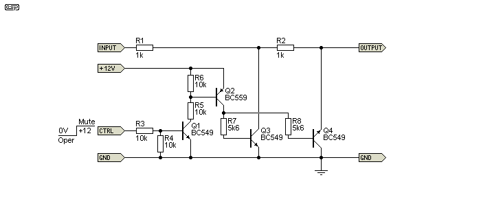
I've shown a dual version above, and Q4 appears to be wired backwards. In fact, it is backwards, with the collector used as the emitter. Transistors will still work when connected like that, but with very low gain. Where the forward gain (hFE) may be 300 or more when wired normally, it may only be somewhere between 1 to 10 when reversed (this is device dependent). Some devices may even show gain of less than unity when reversed. A BJT operated as a muting switch works as a normal transistor for only one polarity of the input signal, and is reversed for the other. That's the reason for using a higher base current than you would use otherwise.
The attenuation is better than you might imagine. 60dB is easy to achieve, although there may be a small DC offset when the muting transistors are on. I simulated 0.8mV for the circuit shown, but measured a little more than that during a single transistor bench test - about 2mV, which is nothing to worry about. Distortion with 5V RMS input and with the base open circuit or connected to -5V was the same as my oscillator's residual (0.02%). The on resistance of the BC549 I tested was 3Ω. This isn't as good as the Rohm 2SD2704K transistor (1 ohm with 2mA base current), but is significantly better than the J111 JFET. The residual voltage is distorted, but it's also at around -82dB referred to the input voltage, so can (probably) be ignored.
Project 147 shows a complete stereo muting system based on BJTs. You can also use PNP transistors for muting, but of course the base drive polarity (and drive switching circuit) must be reversed.
Enhancement mode MOSFETs can be used for muting, but two are needed, connected in 'inverse series' to get around the issue of the internal body diode. They can work very well, but the need for two is a bit of a nuisance. The fact that they need a DC gate voltage to be turned on is a disadvantage, but it's all the greater because it has to be a floating supply. This means that the overall circuit becomes much more complex to the point where it's not worth the trouble. A highly simplified version is shown below, using a 9V battery as the power source and an optocoupler to turn the MOSFETs on and off.
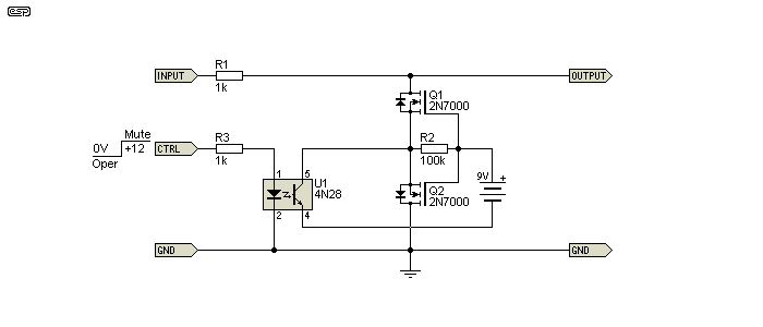
While performance should be very good, the complexity of the complete system is such that it can't be recommended. The process is based on a MOSFET 'relay', and there's more info in the MOSFET Relays article. The article concentrates on switching the speaker lead, but smaller MOSFETs can be used for muting. Note that each muting circuit needs its own separate floating DC supply and optocoupler, and if that doesn't convince you that it's a silly idea nothing will  .
.
You can use a photovoltaic optocoupler to drive the MOSFET gates (it would replace the optocoupler and 9V battery shown). That removes some of the nuisance value, but it's still not worth the effort. The reason ... you can get MOSFET output optocouplers that only need a couple of resistors for less than the cost of a photovoltaic isolator.
If you can get hold of KQAH616D (0.1 ohm on resistance) or LCA110 (35Ω on resistance, and apparently discontinued) MOSFET relays, these do everything. There are quite a few listed on supplier websites, so you can choose the type you can get most easily. I've not tested any of them and can't attest to their suitability, but those I've looked at seem ok. The KQAH616D seems to be unobtanium but you might still find them somewhere. It would probably be better to use them in series with the output, so the signal is disconnected by default. Static protection for the output is essential. Another possibility is the TLP222G (Toshiba), which is another dual MOSFET optocoupler, which has a rated maximum MOSFET voltage of 350V, and a typical on resistance of 25Ω. I've not used any of these, and can't comment on their suitability for audio.
All IC MOSFET relays require a DC source to power the internal LED so they will conduct. I would expect that most people would prefer that they were not in the signal path, although it's not known at this time whether they create any distortion when used to pass the signal (as opposed to shorting it to earth).
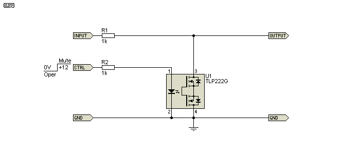
The general scheme using any of the MOSFET optocouplers is shown above, but note that pinouts may be different from those shown for other versions. There is almost no real difference between this and the circuit in Figure 4, except that the need for a floating supply is removed. It's expected that performance will be similar. Although this is potentially a good solution, it requires a supply voltage to mute the signal, and that limits its usefulness.

A single MOSFET can be used if the level is kept well below the intrinsic diode's forward conduction voltage (0.65V). With a level of 250mV RMS, the circuit simulates 0.016% distortion. Attenuation is close to 60dB as shown, which isn't too bad. It can be increased by increasing the value of R1. The signal voltage limitation is a nuisance, but if you're only working with low signal levels that's not a problem. Control voltage breakthrough is low, typically being no more than 20µV.
Light dependent resistors (LDRs) can make an excellent muting circuit, but ideally you need two LED/ LDR optocouplers for each channel because their on resistance is comparatively high. One is used to turn the signal off, with another to short any residual to earth. They are easy to drive and show very low distortion, but the circuit is more complex (and expensive) than a JFET or a BJT circuit. It's possible to get at least 100dB of attenuation, and LDRs have a slow response and very low distortion during the transition. This makes it a 'soft' muting system, where the signal is reduced to nothing over a few hundred milliseconds, and is returned to normal in a similar timeframe.
You can use commercial LED/ LDR units (typically Vactrol™ VTL-5C4 or similar), or you can make your own. Full details on how to build a LED/LDR opto isolator are provided in Project 147. If you make your own, they will not be quite as sensitive as the VTL-5C4, but they work well and are fairly cheap. Make sure that the LDRs you use have a high dark resistance - greater than 500k if possible. This is the only (simple) version that is suitable for partial muting without distortion.
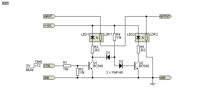
The slow response (fade-in, fade-out) would seem to be necessary, but in reality it's simply a nice touch and certainly not essential. The LED/LDR optocoupler is one of the few methods that doesn't cause distortion as the signal fades in or out so it can be as slow as you like.
When the 'CTRL' input is high, Q1 conducts, and current flows through R3 and turns on LED1. Q1 also removes base current from Q2 via D1. D2 is included to ensure that Q1 can take all available base current so that Q2 remains off. LED2 is off, LDR2 is high resistance and LDR1 is low resistance. The signal is passed normally. There are many ways that the LEDs can be driven (opamps, TTL inverters, micro-controller, etc.) and the circuit shown is merely representative.
When the 'CTRL' input is low, Q1 can no longer 'steal' the base current for Q2 (supplied via R4) so Q2 conducts and LED2 is on. This passes signal to ground, and since LED1 is off the remaining (small) signal is fully attenuated by LDR2. The diodes are essential, and without them the circuit won't work. Without power, there is some muting because both LEDs are off, and the LDRs will be high resistance. The attenuation depends on the dark resistance of LDR1 and the input impedance of the following stage.
While using diodes to switch a signal on or off may seem unlikely, it can be done, and some early compressor/limiters used diodes as a variable gain element (as seen in Figure 7). You might expect distortion to be high, but that's not necessarily the case. When off, there isn't much distortion, provided there are enough diodes to ensure that the signal peaks don't exceed the diode forward voltage. The signal is attenuated by passing current through the diodes, which lowers their impedance. The main disadvantages of using diodes are the need for very close forward voltage matching to avoid DC offset when the signal is muted, the circuitry needed is more complex than for any of the other methods, and the current drain is higher than most of the other circuits. It's included here only because diode switching is an option that most people have never come across, and it has some interest value (if nothing else).
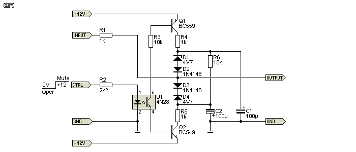
All things considered, it's very difficult to recommend using diodes because they don't work as well as any of the other mute circuits shown. There is also some risk of distortion for high level signals, and it's very hard to ensure that no sensible signal level will cause the diodes to partially conduct. Attenuation for the circuit shown will be around 35dB, and you can be assured that there will be some DC offset, even if the diodes and zeners are perfectly matched. Even the simulator I use (which by default has perfectly matched components) shows 12mV offset, and about 0.02% THD with a 707mV input signal. These are not good results compared to the alternatives, and the attenuation is barely acceptable.
The circuit shown also has a slow and distorted recovery when the mute signal is removed. It takes around 500ms for the signal to return to normal, and during the 'fade-up' process, there is significant distortion. R6 was added to reduce the recovery time to something tolerable - a lower value can be used, but other changes will be needed to restore an acceptable attenuation.
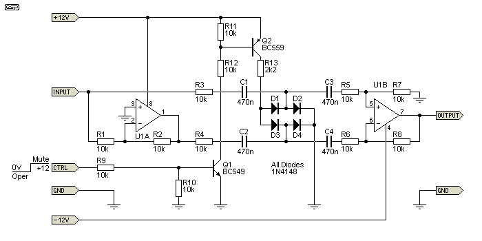
Another diode circuit is shown above. This is considerably more complex, because the only way to ensure that there is no DC imposed on the output signal is to use a differential amplifier. The diode bridge is driven differentially, so an inverter (U1A) is used at the input. The input level should remain below 400mV peak at all times, or distortion is very high. Surprisingly little current is needed to reduce the level, and only 140µA will cause attenuation of over 23dB. As simulated, 50% attenuation is achieved with only 14µA diode current.
Distortion with no attenuation is around 0.14% with an input of 350mV peak (250mV RMS near enough), but with 20dB of attenuation that rises to 0.4%. Worst case (50% attenuation) distortion is over 6%, so while this type of circuit can work reasonably well for muting (albeit with higher distortion than is desirable), it's not usable for linear attenuation (so it's not useful for gain control for example). Like all diodes switching systems, this circuit is very limited in the allowed input voltage. The mute attenuation is quite good, at 58dB as shown.
Muting is very fast, but recovery is slower, as the four capacitors must discharge before the signal returns to full level. With the values shown, it takes around 100ms for the signal to return to 90% of the normal level. Full output is reached after a little over 1 second.
Diode switching is very common in radio frequency circuits (transmitter/ receivers in particular). Because RF signal levels are typically fairly low compared to audio levels, distortion isn't generally a problem, and they can switch very quickly if DC offset isn't an issue. This is usually easily dealt with in RF circuits, and very low capacitance values work because the frequency is high (several MHz up to GHz). However, a discussion of RF diode switching circuits is outside the scope of this article.
Devices such as the 4066B CMOS bilateral switch can be used both for signal source selection and muting. They are quite linear, but the peak audio amplitude is limited to around ±7V (5V RMS) because they cannot be operated with a supply voltage above 15V (±7.5V DC). Their on resistance is typically around 80Ω, somewhat higher than desirable for many applications. If you use one to disconnect the signal and another to connect the output to earth (as shown below), the muted signal will be better than 80dB below the normal level.
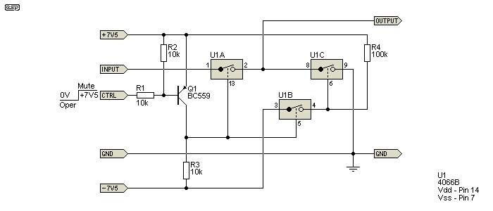
Q1 is used as a level shifter, because the 4066 operates from ±7.5V (the maximum allowed). If the 'CTRL' input is connected to a voltage of 7.5V or is floating, Q1 is off, and the control signal to U1A and U1B is low, so they are turned off. U1B is configured as an inverter, and when it's off, U1C gets +7.5V (via R4) at its control input so it is turned on, shorting the output. When 'CTRL' is brought low (typically earthed), Q1 turns on, thus turning on U1A and U1B. U1B in turn removes the control input to U1C, which now turns off. The signal is passed normally. The unused switch should have its control input (Pin 12) connected to -7.5V and input/ output pins (10 & 11) connected to GND.
These ICs have extremely high input impedance for the control signal, and quiescent current drain is exceptionally low - around 0.01µA at 25°C. They are static sensitive, and direct connection to the outside world is not recommended unless protective diodes are used. Even so, there is always the likelihood of damage if an un-earthed amplifier is attached without grounding it first.
CMOS switches are common in many audio circuits, but they will degrade the sound quality - whether the degradation is audible or not is another matter. They are very sensitive to static because of their exceptionally high internal impedances. Since they are off by default, the supply voltages must be maintained so they can mute, and they must have their supplies present before they can mute any power-on noise. This is a limitation with all circuits that do not provide at least a partial short with no power.
Most digital pots provide a mute function. Some use internal logic to set the 'pot' wiper to zero to mute the signal, and return it to the previous setting to un-mute. There are so many and they are so diverse that it's not possible to show a representative circuit. If you intend to use a digital pot, then you have to work out how to access the various functions. Most need a microcontroller to send the digital codes needed to change volume, mute, etc.
Many digital pots are configured to use 'zero voltage switching', and they only make a change when the signal voltage is close to zero. This avoids the slight click you may hear from a relay, JFET or BJT muting circuit, as these are close to instantaneous. No schematic is shown for a digital pot, because there are too many different types and the application notes or datasheets will have the information needed.
There is the option of using VCAs (voltage controlled amplifiers/ attenuators) to control the level of multiple channels of an audio system simultaneously. The circuit is shown in Project 141. This is easily muted by shorting the control voltage to the positive supply. The signal will be reduced to zero smoothly, with no distortion, clicks or pops. Unfortunately, this mutes the signal, but not the output, and this may result in the VCA itself making odd noises during power-on and off - this depends on the VCA and opamps used.
Many IC power amps have provision for muting, and in some cases standby as well. These functions work well, but are really only applicable for integrated amplifiers that use an IC power amp. Most are easy to use, and typically the signal is muted until a voltage is applied to the mute pin. This varies depending on the power amp - TDA7293 and LM3886 both have a mute function, but they work differently. With an LM3886 the mute pin is connected to the -ve supply (usually via a resistor) to un-mute the output, but with the TDA7293 the mute pin is connected to a +ve voltage of 5V or more.
There are many others, including Class-D (switching) amplifiers that provide a mute and/ or standby function. To understand each type requires you to look at the datasheet for the specific IC you intend to use. Being able to mute a power amp for home use isn't actually as useful as it seems, unless the system is an integrated amplifier, with both preamps and power amps in the same enclosure.
Ducking is a special case of muting. It's traditionally used in shopping centre PA systems, and also in radio broadcasting. The term comes from the background audio 'ducking' (as in reducing level, nothing to do with ducks) when an announcement is made. Unlike muting circuits, ducking does not mute the background audio, but reduces it to a preset level in the presence of an announcement. To implement this properly, the circuit should have a nice, controlled action. Not too fast or too slow, but at a rate that doesn't introduce any noise or distortion. An LED/LDR optocoupler is ideal, because they have characteristics that are almost perfect for this application.
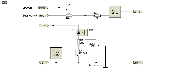
The basic idea is shown above. When speech is detected, the LED turns on and the LDR has a low resistance. The amount of attenuation is set by VRa1, and ranges to almost complete elimination of the background signal (typically around 23dB) with VRa1 at minimum, to just a slight reduction (about 2dB) with the pot at maximum resistance. The range can be increased or decreased by adjusting the resistor values.
This is a simple explanation of the process, and is not intended to show a complete system. The audio detector is a fairly critical part of the circuit, as it needs to be able to detect even quiet speech and handle loud speech equally well. This isn't especially difficult, but the circuitry required is not described here, because the article is more about covering applications and ideas, rather than complete circuits. For a complete ducking circuit, see Signal Detecting Audio Ducking Unit.
Many sources (e.g. CD/ DVD/ Blu-Ray players, etc.) are not earthed, and they use switchmode power supplies. In all cases, there will be a Y-Class cap from the DC output of the supply back to the rectified incoming mains. This is done so the unit will pass EMI tests, but it also causes the output to float at some AC voltage above earth (anything from 50 to 120V AC). Even a 1nF Y-Class cap can provide more than enough instantaneous current to damage opamp inputs and outputs and other sensitive circuitry.
The standard RCA type connector doesn't help matters, because the centre pin (signal) makes contact before the shield, so circuitry can be subjected to whatever voltage is present at the time, with the steady-state current limited by the capacitor. It's not steady-state voltage or current that causes the problem, it the instantaneous current that is delivered at the instant the centre pin makes contact. Touching the outer shield part of the connector to the chassis before inserting the plug may help, but it's certainly not a reliable way to ensure nothing is damaged. It's far safer to use a clip lead or similar to link the two chassis before plugging anything into the RCA sockets, or ensure that AC mains power is removed from all equipment before making connections.
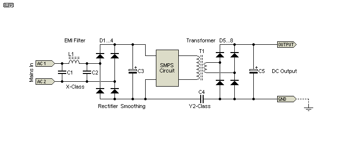
In a typical SMPS as shown above, C4 (typically Y2 Class) is the one that causes all the trouble, even though it's usually rated at no more than 1nF. It combines with the primary to secondary capacitance of T1 to provide a low current path between the incoming AC and the DC output. Provided the secondary is earthed, only a tiny current flows, but if it's not earthed, momentary contact can cause an instantaneous current of several hundred milliamps. If that only flows in the chassis or circuit common it's unlikely to cause any problems, but when the connection is made via the signal lead the momentary current spike can easily damage sensitive components.
The steady state current is around 50µA, but the peak current is limited only by the total circuit impedance. The peak voltage across C4 can be as much as the AC mains peak (325V for 230V mains), and whether anything is damaged or not depends on the exact instant in time when the connection is made during an AC cycle, and the relative speed of the connection. Metallic contact usually makes one or more fast, low resistance connections as a plug is inserted. The peak current can easily exceed 1A, albeit for a very short period (around 1µs or so). That's all it takes to damage any semiconductor.
This is something that I've tested extensively, and there is no doubt at all that even a comparatively rugged TO-92 transistor can be degraded or destroyed by a single input pulse from a Y-Class cap set up to simulate real world conditions. It's (apparently) common for muting transistors to be damaged or destroyed, because they connect directly to the output of many products, including media players, game consoles, TV sets and many others. Even a 'smartphone' that's connected to a charger and then to some other gear via the headphone socket poses a risk, because the charger uses the same capacitor 'trick' in order to pass EMI tests.
There are two main types of muting circuits. A common need is to mute the system (or an individual channel of a mixer) by means of a switch. This may be hardware (a physical switch), under software control (common in mixing consoles), or from a remote control. A single relay can be switched by several different circuits, simply by removing power to force muting. This creates a logical 'OR' gate - if 'input 1' or 'input 2' or 'input n' is applied, the relay will be on and the signal is not muted. If multiple circuits can mute the system, care is always necessary to ensure that you always know that there is a mute signal active, and where it's coming from. It's generally best to have an indicator on each sub-system that can force the mute, rather than a single LED that shows that the system is muted, but without providing any clue as to which circuit is responsible.
Mostly (at least for hi-fi) this isn't an issue, as you may have a power-on/ off mute, and the same relay controlled from a remote. The power-on mute will clear after a few seconds without you needing to do anything, and the remote mute will be activated/ deactivated as required (this is not included in the circuit shown). Using multiple mute relays on the same audio bus should be avoided if possible, because it makes fault-finding much harder if there's a problem a few years after the gear is built.
Muting systems can be operated with a simple analogue circuit, and/ or may be under the control of a microprocessor. Either way, the system has to know when the mains power is turned on or off, so that muting can be applied or removed as needed. For an entire system that controlled by a micro of one kind or another, it will probably be programmed to activate the mute circuits before power is turned off (typically with a relay, also controlled by the micro). Most hobbyist systems don't use microcontrollers, because many people want a purely analogue circuit, without having to worry about digital switching noise getting into the audio.
When a piece of AC powered gear uses a mute circuit, it's commonly set up so that there will be a delay after power-on, and a 'loss-of-AC' detector will be used to mute the signal before the power supply filter circuits can discharge. For a variety of reasons, some circuits will generate loud 'bangs' or strange noises as the supply voltage collapses, and it's a very common requirement that the output should be muted as soon as power is disconnected or turned off. Using a double-pole switch for mains 'on' is a really bad idea, as it's potentially dangerous if a switch fault develops, and it does nothing to mute the output if the mains lead is disconnected.
There are many ways that AC detectors can be set up, with both Project 05 and Project 33 incorporating a loss-of-AC detector and mute circuitry. Ideally, the circuit would mute within a single cycle of the AC waveform, but this isn't always desirable or practical. However, any such circuit should respond within 50ms (5 cycles at 50Hz) to be useful. Extreme precision isn't necessary, but fortunately it's quite easy to do. A single circuit can both provide an initial delay (around 1-2 seconds is generally enough), and provide loss-of-AC detection.
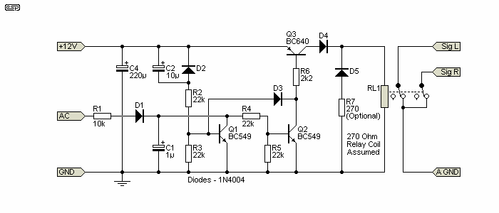
While it's shown as a single circuit, the muting and loss-of-AC sections can be separated and used individually. The circuit is deliberately as simple as possible, consistent with it being able to perform well in practice. The AC input will typically come directly from the low-voltage transformer that provides the 12V DC to operate the circuit. As shown it should be a maximum of 20V peak, and it will be half-wave rectified because of the power supply's bridge rectifier. The voltage developed across C1 should be no more than 10V (average).
Initially, C1 is prevented from charging by Q1, which is turned on for about 800ms via R2 and C2. Extend the power-on delay by making C2 a larger value. For example, if you use 47µF, the power-on mute is extended to about 3.5 seconds. Once Q2 turns off (because C2 has charged), the output from C1 can turn on Q2, which turns on Q3. D3 adds hysteresis to make the circuit turn on cleanly and without relay chatter. When the AC signal disappears (because the mains has been interrupted), C1 discharges quickly, and the relay will have power removed within around 50ms. Once the relay releases, the contacts close, shorting the signals from the two input channels (shown as 'Sig L' and 'Sig R' for convenience only). D2 ensures that C2 is discharged when the 12V supply is turned off.
R7 is optional, and should be the same value as the relay coil's DC resistance. It will allow the relay to release faster. This is covered in some detail in the Relays article. Without the resistor (only the diode D3), the relay may take up to 6ms to release after power is removed. The resistor improves this to about 2.6ms with the relays I tested. The extra 6ms should normally make no difference, but it's a relatively unknown trick that can be included 'because you can'.
As you can see, all of this has been achieved by three transistors and a small handful of other parts. It can (of course) be made far more complex, and it may even be possible to improve its performance a little. The circuit is actually a hybrid, using elements of both Project 33 and Project 05. As shown, it will do exactly what it's meant to do, reliably and for many years.
The output doesn't have to power the relay, and it can be used with any mute system that releases when supplied with a positive voltage. The polarity can be reversed with another transistor if necessary.
The circuit shown is one of many approaches you can take, with the appropriate interface taken from any of the other circuits shown. It's also fairly easy to re-configure any of the circuits shown to perform in the same way. There are too many options, and it would be folly for me to try to show every combination you can use. There is another that's worth including, because it's easily built using a single 4093 CMOS quad Schmidt NAND gate.

It has the advantage of making either polarity available (High = Mute or Low = Mute), and it consists of the IC and a small handful of other parts. It was originally designed to be part of the Project 236 AC millivoltmeter, but it works so well I've added it here. This can be used with any of the circuits shown above, and it's not at all fussy about the supply voltage provided it can never exceed 15V.
The outputs can drive a transistor for relay muting. The base should be driven from the selected output (normally -Mute, U1 Pin 4) via a 10k resistor. Relay wiring is the same as shown in Fig. 1. The 'loss-of-AC' cutout is particularly useful, as it mutes the signal when AC is removed, and prevents noises as the circuitry loses power.
The ideal mute circuit will attenuate the signal in the absence of power, so the signal is muted by default. It needs an active system to allow the mute to be removed, which will be done after all circuitry has had time to settle after power is applied. It will mute the signal immediately when mains (or battery) power is removed, before any filter caps have had time to discharge to the point where opamps become unhappy. With a typical supply filter cap of 1,000µF prior to the regulator and a current drain of around 100mA, a 15V supply will take about 100ms before the voltage is low enough to cause some opamps to misbehave. This is plenty of time for the mute voltage to be removed so most noises can be suppressed fairly easily.
Only the relay and JFET mute circuits satisfy the above criteria.
Mute circuits that require a voltage to be present pose additional difficulties, because some means of holding up the supply voltage for the mute circuit has to be provided. A capacitor will usually do nicely, but it needs to be fairly large to ensure that the mute is maintained until all 'disturbances' have ended. It's not hard, but it does add extra parts. Providing a supply voltage before anything else gets power is much harder, so if you have equipment that makes noise at power-on your choices are limited.
It's very hard to beat a relay. The mute/ un-mute action is sudden and creates some transients, but the effect is not usually a problem. It may not have the finesse of a nice soft action as you'll get with a LED/LDR combination, but it does what's needed reliably and with the absolute minimum of additional components. An added benefit is the fact that the mute is active in the absence of power, and the circuitry has to provide a DC voltage to activate the relay and remove the mute. This helps to protect the output stages of your equipment from static damage. The relay is the simplest and most effective of all muting circuits.
Relays are also completely immune from damage caused by plugging in RCA leads. With these, the centre pin makes contact first, and any static charge (or the voltage that can be measured from all 'double insulated' and other un-earthed equipment) can't damage the contacts. The short circuit to earth/ ground provided by the relay also protects the rest of the circuit.
The next best option is JFETs, but their attenuation is not as good as a relay. The JFET is also static sensitive, and protection is needed to prevent static impulses from destroying the JFET. While BJTs actually work surprisingly well, they require more external circuitry than a relay or JFET so are not very good candidates.
There is a lot of very confused thinking on the Web about mute circuits, and what does (and does not) work. Those shown here all work exactly as described, and distortion is generally very low (with the possible exception of the diode circuits). Many people think that using BJTs must cause distortion, but that's only true if they aren't used properly. Perhaps surprisingly, transient distortion (while the signal is being muted or restored) is close to being inaudible provided the transition is fairly fast. If the transition takes less than 100ms, you almost certainly won't notice the distortion from a JFET. However, a BJT produces highly asymmetrical distortion during the transition and that may be audible under some conditions.
References are few, because there's surprisingly little information on the Net. There are certainly a few circuits (and more than a few forum posts), but finding definitive info is not easy, and this article is intended to bridge that gap. It's quite obvious that many of the comments made in forum posts and elsewhere simply show that the writers don't understand muting circuits at all.
 Main Index Main Index
 Articles Index Articles Index
|