
|
|
| Elliott Sound Products | Project 104 |
 Main Index
Project Index
Main Index
Project Index
So, your preamp or crossover insists on making rude noises as the power is turned off? If this happens, there is only one thing you can do, and that's to add a muting circuit that will disconnect the audio as soon as power is removed. There are several ways this may be done, but the simplest (and least intrusive to the audio signal path) is to use relays that short the outputs of the preamp, crossover or other circuit.
Placing a short on the outputs will not damage the opamps (or even discrete circuits), provided there is a limiting resistance in the output - since it is almost mandatory that a 100 Ohm (or thereabouts) resistor is used to prevent oscillation, no further action is needed. In addition, nearly all opamps are protected against shorted outputs anyway.
Other methods are relays that connect the audio, so then you have contact resistance in series - not usually a problem, but many purists will not be happy with this. There are CMOS switches, but these suffer from non-linearity problems, and are not recommended. Then there are FETs or bipolar transistors, but the distortion added by these is IMO just not acceptable at all.
The unit is connected to a new or existing preamp, crossover or errant signal source as shown in Figure 1. The relay voltage needs to be selected according to the unregulated DC voltage. In some cases, it will be necessary to add a resistor (R8) in series to obtain the correct operating voltage for the relay(s). For example, if the unregulated DC is 20V, you will need to add resistance in series with the relay coil to drop 8V (assuming 12V relays). How to work out the resistor value? This is covered below.
For multi-channel systems, crossovers and other places where there are multiple signal sources to mute, it will be necessary to use more than one relay. It may be possible to use relays in series to make up the DC voltage - 4 x 5V relays in series will work just fine on an unregulated 20V DC supply. Relays will tolerate a slightly higher voltage than their ratings indicate, but I don't recommend more than 20% or so - for example, a 12V relay will usually be quite happy at up to 15V. R8 is easily calculated, based on the relay coil resistance and the measured supply voltage. Use the following method ...
Vd = Vs - Vr (where Vd is Voltage drop, Vs is supply voltage and Vr is relay coil voltage)
Ir = Vr / Rr (where Ir is relay current, Vr is relay voltage and Rr is relay coil resistance)
R8 = Vd / Ir
For example, a 12V relay has a coil resistance of 175 Ohms, and the unregulated supply voltage is 21V DC ...
Vd = 21 - 12 = 9V
Ir = 12 / 175 = 0.068A (68mA)
R8 = 9 / 0.068 = 132Ω (Use 120Ω)
Power rating = V² / R = 9² / 120 = 0.675W (use 1W)
While there is a small error there (the coil voltage will be slightly over 12V because R8 is smaller than calculated) it is of little significance in real terms. If in doubt, always use a resistor with greater power handling than you need - for example, a 5W resistor is overkill, but will do no harm.
 | Note that the relays must not be operated from the main regulated DC supply for your preamp or crossover. This is likely
to cause more and nastier noises than before the circuit was added, which rather defeats the purpose. In addition, this may also cause the positive regulator to overheat. It is
also very important to keep the relay coil wiring as far removed as possible from the audio signal leads. Transients created by switching relay coils are easily coupled into the audio
circuit, despite its low impedance. If preferred, use another pair of diodes and a filter cap to create another supply to run the mute circuit. Note that it will share a common earth/ ground with the main supply. |
The circuit for the mute system is shown in Figure 2. Using a 4584B CMOS Hex Schmitt trigger inverter IC, a couple of cheap transistors and a small handful of other components, there isn't a lot to it. Despite the simplicity of the circuit (and yes, it really is simple), it will short the preamp or crossover outputs to earth for about 0.5 second after power is applied, and will re-apply the short within 30-50ms after power is removed ... well before the supply voltage collapses. The mute time may be extended by increasing C2 - a maximum of 33μF is suggested, which will cause the system to mute for about 2 seconds after power is applied. If C2 is a low-leakage type, you can increase the value of R3, but I wouldn't exceed 1MΩ.
Unmarked diodes are 1N4148 or similar, and all caps are rated at 25V or greater. D5 is a 5.1V zener, and may be rated at 400mW or 1W (the latter are much more common). Q1 can be any small signal transistor with a voltage rating greater than the unregulated DC supply voltage, and Q2 can be any medium power transistor. In many cases, a small signal transistor may also be used for Q2, provided the relay current is within the transistor's maximum current rating (typically only 100mA or so). R7 is there so you can test the circuit without having to use a transformer. Without it, the relay state will be indeterminate at power-on if nothing is connected to the AC terminal.
If you have a switched DC voltage within the preamp (or crossover), the 'AC' terminal can be connected to the switched DC (which must be positive with respect to ground/ common). Operation is essentially unchanged, but the switch-off (mute) may be delayed if the following circuitry has a large bypass capacitor.
The CMOS Schmitt trigger is ideal as a timer, and also makes an excellent 'loss of AC' detector. U1A and U1B cover this function, and U1C is the mute timer. The remaining Schmitt inverters are connected in parallel to ensure sufficient base drive to Q1. If you can't get the 4584 in a DIP package, you can also use a 40106, a 74C14 or a 74HC14. Perhaps somewhat remarkably, they all use the same pinouts.
D1 and D2 prevent potentially destructive input voltages to the CMOS IC, and R1 limits the current to a safe value. Provided AC is present, the output of U1A pulses low 50 (or 60) times per second, and via D3, keeps the voltage on C1 below the trigger threshold of U1B. When power is first applied, there is no voltage at all, but it builds up to full voltage within a couple of cycles. U1C is prevented from sending its output low by C2 (mute timing capacitor). Provided the applied voltage is maintained, C2 charges up via R3 until the input threshold of U1C is reached. At this time, U1C will send its output low, thereby sending the outputs of U1D, E, and F high. This turns on Q1 and Q2 and energises the relay. Since the output of the preamp (etc.) is normally shorted to earth (ground), the short is removed and normal operation occurs. The signal must be connected to the normally closed relay contacts.
Should the AC fail or be switched off, C1 charges rapidly (well before the preamp supply voltage collapses), and there is nothing to prevent this (U1A is not pulsing low any more). When the threshold voltage of U1B is reached, its output goes low immediately, discharges C2 via D4, and turns off the relay. This places a short across the audio signal and mutes the signal. The relay drive is removed in less than 25ms with the values shown - the relay itself will short the outputs typically within 30ms after AC is removed.
The relay itself should be a miniature DPDT (double-pole, double-throw) type, and suitable units are available from all major suppliers. They are inexpensive, and the hermetically sealed types will usually be very reliable for many years. Being sealed from the outside atmosphere, there is nothing to tarnish the contacts. You can also use reed relays - but only if you can find them with normally closed contacts. They do exist, but are far less common than normally open contacts. Using the relay contacts to short the signal is preferable to using them to switch the signal on, because when powered on, the scheme shown means that there is nothing in the signal path that may cause distortion. Dirty or tarnished contacts can create distortion under some conditions.
No PCB is available - if enough people ask, I will produce boards and make the PCBs available for the circuit. In the meantime, it can be made reasonably easily on Veroboard or a similar prototyping board. If a PCB did exist, it would look very similar to the prototype shown in Figure 3. Considering the fact that this project was published in 2004 and no one has asked, I must assume that a PCB is not warranted.
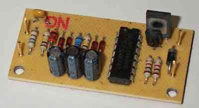
Board size for the prototype is approximately 54 x 27mm (2.1" x 1.1"). Naturally, (if produced, which is unlikely) production boards will have the silk screen overlay and use fibreglass PCB material (rather than the glass/phenolic board shown). The size of the board is such that it can be tucked away in any convenient location, and the relays would normally be physically located as close to the output connectors as possible. It goes without saying that a PCB makes it very easy to assemble and very hard to make a mistake.
Be careful when handling the CMOS IC, as static can damage the IC quite easily - you may not even feel the discharge, but the IC will be dead. Use an earthed soldering iron, and avoid rubber soled shoes, carpets and other static generating items.
R6 is determined by the DC supply voltage - CMOS devices draw only a very small current, so the value is not critical. The astute reader may wonder why I have specified a 5.1V zener diode, when the 4584B is quite capable of using 15V supplies. Very simple ... many suppliers do not stock the 4584, but will gleefully offer the 74HC14 as a 'direct replacement'. Unfortunately, the 74HC (High speed CMOS) series devices are limited to 6V supplies, and will self destruct at 15V. Keeping the supply to 5.1V means that either IC can be used without worrying about the voltage rating. The zener current should be around 20mA (0.02A), and the IC draws almost nothing. Base current into Q1 will only be in the order of a couple of milliamps.
To work out the value for R6, follow this process ...
Subtract 5.1 from the measured (loaded) supply voltage to obtain voltage drop across R6 (Vd)For example, you measure an unregulated supply voltage of 21V DC
R6 = Vd / 0.02 (value in Ohms)
Vd = 21 - 5.1 = 15.9
R6 = 15.9 / 0.02 = 795 Ω
Use 820 Ω, or two 1k5 resistors in parallel
Power rating is 15.9² / R6 = 0.3W (use a 0.5W resistor)
If you can get genuine 4584B CMOS Schmitt trigger ICs, then D5 can be increased to 12V, and R6 adjusted accordingly. The circuit will work exactly the same at 5V or 12V. D5 current should remain at about 20mA, and R4 can be increased to 2.2k if desired. To calculate R6, use the same formulae as shown above, but use 12V instead of 5.1V in the calculations. 10V Zeners can also be used if you happen to have these on hand. Even if the CMOS supply is not well regulated, the circuit will still work fine - the zener is required though, as any over voltage (however brief) may damage the IC.
If you do want to use a 12V zener - which I did in my prototype as I had a few 4584Bs but no 5.1V zeners in stock - then R6 would be equal to ...
Vd = 21 - 12 = 9V
R6 = 9 / 0.02 = 450 (use 470 Ω)
Power rating is 9² / 470 = .17W (0.5 or 0.25W resistor will be fine)
The same process can be used for any other zener voltage, but do not go below 5V or above 15V - any value you have handy that's in between those will be fine - but only for a genuine 4584B or direct equivalent, such as 74C914. Suitable devices are ...
15V - MC14584B (Motorola / On-Semi)
15V - BU4584B (Rohm)
15V - MM74C14 (Fairchild)
5V - 74HC14 (various)
There are many different types, so be sure to download the data sheet for the device you can get before ordering zeners and such. It is very important that you don't apply more voltage than the IC can withstand. Do not even try to use a TTL (Transistor-Transistor Logic) IC in this circuit, as it will not work. It must be CMOS.
Connect to a suitable power supply - remember that the supply earth (ground) must be connected! When powering up for the first time, you can use a 100 ohm to 560 ohm 'safety' resistor in series with the DC supply to limit the current - this will save damage if you have made a mistake in the wiring. Verify that you have the appropriate voltage (5.1V or 12V) across the zener (D5) and that nothing gets hot.
If all is well, connect the board to the power supply as shown in Figure 1, and connect a suitable relay. A back EMF suppression diode is not needed, since this is already in the circuit (D6).
With only DC applied, the circuit will do nothing at all - an AC source may be connected to the AC terminal, or you can use a clip lead between the AC input and the DC supply for testing. When power is applied, the relay(s) should click after about 0.5 second. When DC or AC is disconnected from the AC terminal, the relay should release almost immediately. To ensure that U1A actually switches, the AC terminal should is returned to earth (ground) via a resistor (R7) - this is only needed for testing but does no harm if permanently connected. Normally the transformer will provide the necessary DC return path.
Verify that the relays are connected properly by measuring with an ohmmeter - the preamp (etc.) outputs should show a short circuit to earth with power off. This should change to some higher value (which depends on the circuit topology) when the relays operate.
Main Index
Project Index