
|
| Elliott Sound Products | Project 147 |
In general, muting and/or signal switching is done by relays, FETs or CMOS analogue switch ICs. All have limitations, but a little known technique that really doesn't look like it could ever work is to use bipolar transistors.
The design shown here has extremely low distortion when turned off, and also has very little signal 'breakthrough' when turned on. Performance is far better than a FET, and unlike analogue switch ICs, you don't need to mess around with odd power supply voltages. In the off state, distortion is typically less than 0.004% and attenuation in the on state is better than 55dB.
This behaviour is probably unexpected - everyone knows that you can't apply an AC signal to an unbiased transistor. However, you can, provided certain conditions are met. This project shows you how it's done. It's surprisingly simple to do, and no 'special' transistors are needed.
While this article describes the idea as a project, it's more 'food for thought' than a construction project. Having said that, there will be applications where it's easier, cheaper and more convenient to use the circuits shown than to have to source relays, or to try to wire up CMOS switches for muting. While it is possible to use the ideas shown here for source switching, there will be some messing around and major compromises. I don't think it's really suitable, but you may have other ideas.
Note that although I have shown the circuit using BC549C (highest gain range) transistors (which are readily available almost everywhere), there is no reason that you can't use devices such as the BC546/7/8, 2N2222 or almost any other NPN device. Transistors with a low base-emitter reverse breakdown voltage can be used, but the maximum signal level is reduced before distortion becomes a problem.
This is one of those 'impossible' applications for transistors that defies common wisdom. However, I first encountered it in a commercial tone-burst generator and figured that it was worthy of further investigation. The maximum level is limited to around 3V RMS - above that you are likely to get unacceptable distortion (> 0.1%). The level the circuit can handle is limited by the base-emitter reverse breakdown voltage of the transistor(s) used. If you want, the bases of the gating transistor(s) can be connected to a negative voltage so they are no longer expected to have an almost infinite impedance. There is little to gain by doing so, and based on tests I ran it will actually increase distortion.
Also, be aware that there is a small DC offset when the circuit is on (muting), but at less than 10mV it can be ignored for the most part, provided the following circuitry is not DC coupled. At worst, it may cause a small 'click' when the circuit is activated or de-activated with no signal.

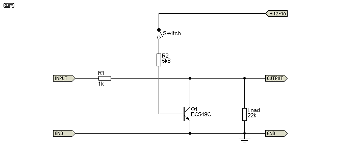
Figure 1 - Basic Test Circuit
The most important part of the circuit is the complete isolation of the base (via R2) when the circuit is off. Even a tiny leakage resistance will cause distortion. However, it's most unlikely that even Veroboard or similar will have enough leakage to cause a problem if you are careful with wiring. Stray capacitance isn't a major issue provided it's less than around 100pF. That's a surprisingly high capacitance to achieve just from normal components and wiring techniques.
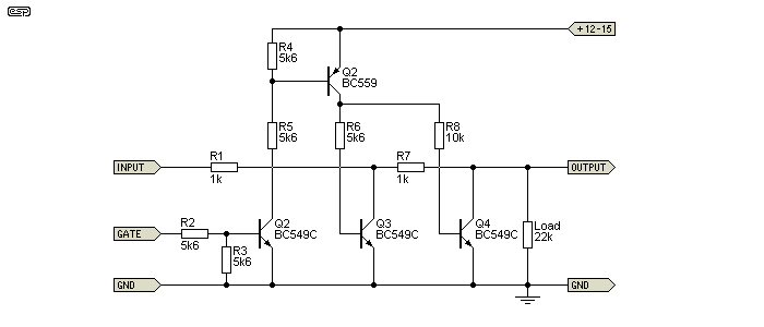
If you need higher attenuation, simply use two transistors, separated by another resistance. Unlike a relay, this signal voltage clamp must have some resistance in series, because the transistors are not capable of shorting the low impedance output from typical preamps without a lot of 'break-through' signal, which will be highly distorted. A single clamping transistor will give an attenuation of around 46dB, but doubling up as shown below increases that to about 90dB - at least in theory. You can certainly expect that the end result will be a well and truly muted signal.

Figure 2 - Dual Transistor AC Voltage Clamp
The control voltage supply (+12 to +15V) doesn't need to be anything special, and will normally be the supply rail for the preamp or other device that needs a muting circuit. If it has a bit of ripple or noise some of it may be transferred to the output when the clamp transistor(s) are turned on, but any noise will be highly attenuated so it should normally be completely inaudible. Switching is virtually instantaneous - the circuit does not provide any gradual or 'soft' switching ability. The signal at the output is either on or off - there is no intermediate state. Any attempt to slow down the switching will cause serious distortion during the transition, and if not done properly may cause distortion even when the switches are supposed to be off.
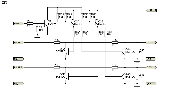
The full circuit for two channels is shown below. It uses the same control voltage from Q1. There are separate control voltage switches (Q2A/B), because they prevent any possible cross-coupling between channels. A single transistor can be used and R6A/B and R8A/B simply joined, but you may get some distorted crosstalk under some conditions. For the small cost of a transistor and couple of resistors, it's not worth cutting corners. All resistors can be standard 5% carbon film types - there is no need for precision. For lowest possible noise, those resistors in the signal path (R1A/B and R7A/B) can be metal film types.

Figure 3 - Complete 2-Channel AC Voltage Clamp
To mute the signal, it is only necessary to apply a positive voltage to the 'Gate' terminal. We need a base current of at least 0.5mA into Q1 to ensure that Q2A/B turn on fully, so R2 is nominally 5k6 (assuming that the switching voltage is 5V DC or more). If the voltage is lower, then R2 should be reduced in value. For example, with a 3.3V supply as used by some micro-controllers, R2 should be around 2.2k. The value can be increased for higher voltages, but the value shown is quite safe at up to 15V.
If your auxiliary circuitry normally pulls its output to earth to activate muting (for example an open-collector output from a micro-controller or other logic), then Q1 can be omitted - the resistors (R5A and R5B) must be retained ! Make sure that the source allows its outputs to be pulled above the logic supply voltage, or the circuit will mute permanently.
Remember that the collectors of Q2A/B must connect to nothing else in the circuit - they have to be floating. You will see that base-emitter resistors aren't used on Q3A/B or Q4A/B, because adding them will cause gross distortion at any level greater than 0.6V peak. Even as high as 1M will increase the distortion by a factor of at least 10!
The circuit, either in whole or in part, can be used anywhere you need to mute a signal. The signal level should not exceed 5V peak (3.5V RMS) or you may get audible distortion. It is useful as a general-purpose mute circuit either at the output of a preamp or the input of a power amp, or can be used to turn an effect (such as reverb in a guitar amplifier) on and off.
It can also be used for gating a test tone or even as an on/off switch for a test oscillator. Speed is high enough that it will easily gate a 20kHz signal with little or no waveform distortion. Note that it must not be used in series with an inverting mixer input stage - it is designed for high impedance loads of 10k or more. Likewise, the source impedance will affect performance. With a relatively high source impedance (1k or more) the circuit will be more effective.
In short, it's a useful and versatile muting switch for AC signals. Using it to mute very low-level signals is not recommended, because the DC offset when the gating transistors turn on will become troublesome.
This is another unusual design in the ESP projects list. Firstly, it is a very unconventional use for bipolar transistors in a (relatively) distortion-free muting circuit. It has far greater attenuation than most FETs in this role, and it doesn't need a negative supply to turn the gating transistor(s) off.
At most settings that will be used and with typical input and output voltages, distortion can be expected to be well below 0.01%, and it only becomes worse with high signal levels (greater than 3.5V RMS). As noted earlier, it's a circuit that is presented primarily as a tool for experimentation - there are several likely uses for it that I can think of, and I hope that someone finds it useful and as interesting as I did when I saw it.
 Main Index
 Projects Index