

|
| Elliott Sound Products | Microphone Splitters |
 Main Index
 Articles Index
Introduction
1 - Impedance
2 - 48V Phantom Power
3 - Passive Splitters
4 - Active Splitters/ DI Boxes
5 - Active Microphone Splitters
6 - Preamp & Attenuator
7 - Signal & Clipping Detectors
8 - Buffers & Transformers
9 - Combining Channels & PFL
Conclusion
References
This article may appear to be part project, and the schematics shown will all work, but the primary purpose is to discuss the various options when an audio signal has to be split to feed the signal to two or more different pieces of gear. Commonly, a signal is taken from an instrument, and sent to a stage amplifier and a mixing console. It can be a direct feed (from the instrument's output) or from a dedicated 'line output' as provided on some instrument amplifiers. Microphone signals also commonly need to be sent to multiple destinations.
Signal splitters are common in recording and news gathering environments, especially where a live broadcast or recording is made of a live performance. There are many other applications as well, and there isn't a single solution to all possible requirements. If microphone levels are being split, it's common to use nothing more than a purpose designed transformer. There is inevitably some signal loss, but that's often preferable over an active solution because the noise penalty is generally much lower. However, passive splitting cannot be used where multiple destinations are required, because the signal would be greatly attenuated.
The signal from a microphone can vary from as little as a few millivolts up to 1V (RMS), depending on what is being recorded and the microphone being used. A loud singer or a mic that's (often very) close to drums or instrument amp speakers can produce much higher levels than you expect, and losing a few dB of level is no big deal. However, if an orchestra, acoustic instrument or vocal ensemble is recorded from a comparatively distant microphone, the level will be low and using a passive signal splitter will reduce the overall signal to noise ratio.
One of the most popular mics (for a very long time) is the Shure SM58, which has a typical output level of -54.5dBV/ Pa (1.85mV at 94dB SPL), and while most dynamic mics are similar, in practice the sensitivity can be significantly different over a fairly wide range. Capacitor (aka 'condenser') mics usually have a higher output level, while ribbon mics will be generally somewhat lower. Electret mics are also used sometimes, but some many are not be suitable for recording high level (loud) instruments.
So-called 'line level' is actually an undefined term - what you need to know is the peak signal level (in dBV or dBu) and the nominal impedance. For professional audio, the reference level is generally around +4dBu, but may be higher or lower in some systems. +4dBu is a voltage of 1.23V, and the 0dBu reference level is 775mV. Levels can also be referred to 1V RMS (dBV), and +4dBV is 1.6V RMS. Most home equipment operates at lower levels, typically around -10dBV (316mV), but again, some equipment will provide either higher or lower levels depending on the whim of the manufacturer.
It's common to refer to the separate outputs of a splitter as 'sends' - the signal is sent to one or more external destinations, most (if not all) of which are not part of the main installation. These will often be equipment owned and operated by radio or TV stations, or even online streaming services. Since the destination equipment could come from anywhere and be in any form of repair or disrepair, it's important that a fault that affects one send should not interfere with the signal being sent to other destinations.
In most of the examples shown below, there is a single input for a microphone, a 'main' send (which goes to the system mixing console) and two auxiliary sends that can be used for outside broadcast (OB) equipment, live recording or whatever other function is needed. In some cases you might need to split a single microphone feed to multiple sends (perhaps 24 or more) for press conferences, political speeches, etc. Such a system must be active, and each send must be buffered to ensure that if one new gathering organisation shorts their signal line, it doesn't cut off anyone else's feed.
To get full galvanic isolation (meaning that there is no direct ohmic connection) between the various sends from a splitter, a transformer is the only real option. No transformer model numbers are given in this article, because it depends on where you are, what you can get, and what you can afford. Good trannies are expensive and cheap ones usually have poor performance, but even a cheap transformer will often give better results than an expensive (relatively speaking) active circuit. Active balancing circuits and ICs are available, but none provides the complete isolation that you get with a transformer.
When a microphone signal is split with a passive circuit, its level is always reduced. This is due to the load imposed by two or more mic input stages, each of which reduces the level as it's connected. The best way around this is to have a mic preamp at the splitter, but then there is the issue of gain control. These days it can be controlled via Ethernet with an app on a smartphone, but that adds considerable complexity, and everything must be secured against random (malevolent) punters who may find a way to hack the system. I will not even attempt to describe a system controlled via RS232 (serial), Ethernet, MIDI, WiFi, Bluetooth or any other remote system - most systems are proprietary and the details are inaccessible.

| Note Carefully: In the majority of the circuits shown below, opamps are not shown with supply bypass caps. This is for clarity, but in all cases capacitors are required from each supply pin to ground, or between the supply pins. If caps are between supply pins, there should be at least one cap from one or both supply rail(s) to ground. Omission of bypass caps may cause oscillation, especially with fast opamps. However, no opamp is immune from oscillation if not bypassed properly ! |
To many people involved in audio, impedance is often a deeply misunderstood parameter. It's often quoted as being '600 ohms' for example, but for anything other than telephone systems it's generally arbitrary. The source impedance (microphone or 'line out') should be low, and the input impedance of the receiving equipment should be high. Impedance matching is only used when the lines are very long (from several hundred metres to two or three kilometres), where a matched impedance causes maximum power transfer with no reflections (which can manifest themselves as echoes if there's any additional delay - such as intercontinental phone links). This situation is extremely rare for any audio setup. Even in the telephone system, 600 ohms has been superseded by a 'complex' impedance which (for reasons unknown) varies from one country to the next.
Microphones generally have a stated output impedance of around 200-300 ohms, and the mic preamp should present an impedance that's at least 5 times greater. Most mic preamps have an input impedance of around 4kΩ or more, so they don't load the mic and reduce the output level. For example, if a mic has an output impedance of 300 ohms and you load it with 300 ohms, the signal level is reduced by 6dB because you have created a voltage divider. You then have to increase the preamp gain by 6dB to get the same level, so noise is greater - again by 6dB.
The arrangement where the source has a low impedance and the load (receiving device) has a high impedance is known as 'bridging' (the term comes from telephony). Bridging loads are by far the most common in all areas of audio. Preamps may have an output impedance of 100 ohms, and the load will be 10k or more. There is negligible level reduction (less than 0.09dB) and signal to noise is not affected.
The common reference to 600 ohm lines comes (again) from telephony. This used to be the standard nominal impedance of the phone system, and 0dBm is represented by a power of 1mW into a 600 ohm load (775mV). dBu has replaced dBm in most instances now, indicating that we are interested in the voltage, and not the power. The voltage is the same for both, but dBu does not imply an impedance of 600 ohms.
There are some instances where high impedance signal sources (guitar and bass in particular) need the signal to be split so that it goes to the stage amplifier and mixing console. In general, this type of splitter (aka 'DI' or direct input/ injection/ input, etc.) has a high to very high input impedance that acts as a bridging load. The input impedance can be from 100k to 10MΩ and the signal to the stage amp is not affected. The DI box sends the signal to the mixer via a transformer or electronic balancing circuit. A transformer ensures complete isolation, but an active balanced driver does not. One solution is shown in the Project 35 page.
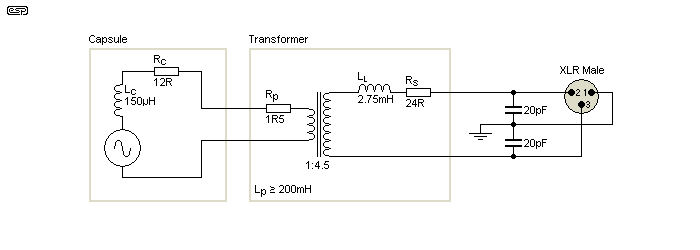
Figure 1 - Dynamic Microphone Equivalent Circuit
Capsule - Lc = voicecoil inductance, Rc = voicecoil resistance, Transformer - Lp = primary inductance, Rp = primary resistance, LL = leakage inductance, Rs = secondary resistance
Figure 1 shows the equivalent circuit of a 'typical' dynamic mic. The values will vary depending on the way the mic is made, and some may use a (relatively) high impedance voicecoil rather than a transformer. These are more fragile than low impedance voicecoils and may be more prone to failure. There are as many variations as there are models from the many manufacturers, so the above is merely representative.
With the values given above, the mic's electrical impedance is 300 ohms. As with any electro-mechanical device, the impedance is a combination of electrical and mechanical (acoustic) components, but the above makes no attempt to duplicate anything other than the electrical circuitry. The model is not meant to be especially accurate, but is close enough for you to get an idea of what's involved.
Phantom power is common for many capacitor (aka 'condenser') microphones, and it's also used to power direct injection (DI) boxes that are used in live sound. However, the current is very limited, because the standard phantom feed is via a pair of 6.81k resistors. This means that the maximum current possible (into a short circuit, so there's no voltage available) is only 14mA. If you need (say) 10V to run the electronics, then the maximum current you can draw is 11mA.
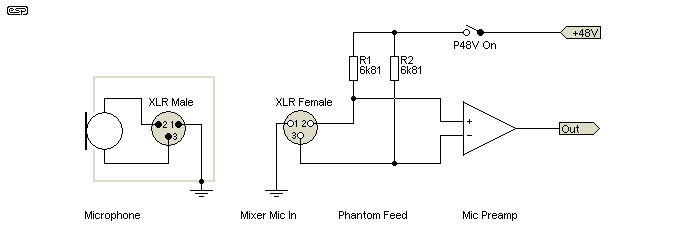
Figure 2 - Phantom Power Feed System
Not included in the above is the essential protection circuitry needed in the mic preamp to protect it against the 48V supply. Project 96 shows a phantom power supply and protection network that is more-or-less typical, and Project 66 is a dedicated mic preamp that is also typical of a high-quality unit.
It's certainly possible to increase the phantom supply current by using a non-standard feed circuit, but that means that your mixer is now non-standard. Making changes to the standard circuit isn't recommended, so it's necessary to design the powered equipment so that it will be functional with any mixing console or other gear that provides 48V phantom power. If this isn't possible (many early capacitor mics with valve preamps for example) then a separate dedicated power supply has to be used.
Phantom power is very limited, and it's also important that a splitter passes the phantom power through to the microphone (or other equipment). However, it should only pass phantom power from the primary (main) mixer. If the auxiliary sends are connected to equipment that also can provide phantom power, the splitter should be designed to not pass phantom power if it's turned on at an auxiliary destination (anything other than the main mixer), and to ensure that phantom power from the main mixer is not passed through to the auxiliary sends.
Failure to ensure proper phantom power isolation could result in damaged equipment. Only the primary/ main mixer should be able to provide phantom power to the microphone, it should not be accepted from (or passed through to) any of the additional sends from the splitter.
All dynamic microphones can accept phantom power - even though it's not needed. No damage will occur, because the same voltage is applied to each end of the transformer or voicecoil, so no current flows. However, if phantom power isn't needed by the end equipment it should be turned off - always !
If you want a completely passive system, you have the choice of either a transformer or resistive splitter. A transformer system has lower losses and can provide galvanic isolation (no resistive path between separate sends), but is costly. You can get cheap transformers, but they will almost certainly have poor performance. A low cost transformer will typically suffer from one or more (perhaps all) of the following ...
Transformers that can safely be used at levels of +4dBu or above with full range material (extending from 20Hz to 20kHz) are expensive. They aren't without loss either, and you can expect to lose between 3 and 6dB of signal level. This isn't usually a problem when they're operated at 0dBu, but if used with a microphone the loss of level will cause an equal increase of noise, because the mic preamps have to be run with extra gain to make up for the loss. When transformers are used, the primary inductance should be as high as practicable to ensure that there is the minimum possible loading on the microphone at all frequencies.
Resistive splitters are cheap to build, but they don't provide any galvanic isolation between the separate sends (increasing the risk of hum loops), and the insertion loss is greater than a transformer. However, they can never clip or saturate at any level, and distortion is virtually zero. Using a resistive splitter for a mic signal would generally be considered a very bad idea, because the loss through the splitter means that more gain is needed at the mic preamps so noise is increased proportionally.
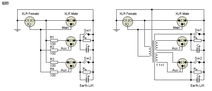
Figure 3 - Resistive And Transformer Splitters
Examples of both a resistive and transformer splitter are shown above. These are equally suited for 'line' level (+4dBu) or 'mic' level (-40dBu, but highly variable). The resistive splitter wins on cost, but the transformer version is a far better option overall. However, it also comes with a fairly significant cost penalty, and that can be a major disincentive if you have to pay from around $50 to over $100 each for the transformers. As noted above, cheap transformers almost certainly won't be up to professional standards. The same transformer often can't be used with both mic and line levels, and you may need splitters for both types of signal. Note the electrostatic (Faraday) shields on the transformer - each winding should have its own shield as shown, or noise can be coupled capacitively from one winding to the next.
The resistive splitter shown is primarily for interest's sake. I wouldn't use it, and I suggest that you don't either. The losses are such that all sends will be attenuated (compared to using the mic directly), and this increases noise because the mic gain has to be increased to compensate for the signal loss. While a fault on one of the auxiliary sends can't reduce the signal level on the other sends to zero, it will attenuate it even further than normal. Use of phantom power is dubious - for the most part it cannot be recommended because the voltage will be fed to all sends as well as the mic. Capacitor isolation is possible, but then extensive protection needs to be provided on the send lines.
The 'Earth Lift' (aka 'Ground Lift') switches and the RC network values for each are likely to be the subject of much debate. In some cases, total isolation may be the best, but that can only be achieved with the transformer version. The resistor (Re) will typically be anything from 10 ohms up to perhaps 1k or more, and the capacitor (Ce) is generally around 100nF. With the resistive splitter, the earth resistance should be kept to a fairly low value, or hum pickup from the cables is likely. The values will be a compromise in all cases, and may need to be determined by experimentation.
Both splitters shown must be enclosed in a shielded metal box, which should be earthed to the main input-output connection. The straight through (Main) output is the one that goes to the primary mixing console - most often the FOH (front-of-house) mixer for live performances.
The passive transformer based splitter has two major disadvantages ...
In all passive systems (including those using transformers), the extra load on the mic due to it having to feed several mixers is only part of the problem. Cables have capacitance, ranging from around 42pF/ metre (low capacitance types) up to 105pF/ metre for 'normal' shielded mic cable. Since there may be several long cable runs - especially if the signal is simultaneously provided to an OB van, the total capacitance can become very high. This capacitance alters the response of the microphone, so the simple act of plugging an extra cable into a splitter causes the frequency response to change.
If 100 metres of cable is connected to a microphone, the capacitive loading will be between 4.2nF and 10nF, depending on the cable used. In a large venue (especially outdoors) there may be a great deal more than 100 metres, and the mic will be affected. The only way around this problem is to use active splitters, which buffer the signal so the mic only 'sees' the cable between its own socket and the splitter.
By definition, an active splitter uses transistors, FETs or opamps to amplify and buffer the signal as needed. This means that it needs a power supply, and this may be from the mains (via a suitable transformer and power supply), batteries or 48V phantom power. Those using phantom power are very convenient, but the available current is low (typically no more than 10mA) so the circuitry must be optimised for fairly low current. Any power supply used has to be safe under all possible conditions, since a microphone is a shock hazard for anyone who plays guitar or bass because the strings of the instrument are always earthed via the musician's amplifier(s).
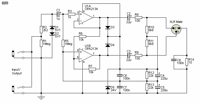
Figure 4 - Active DI (Direct Injection) Splitter (From Project 35)
The above is a splitter, although it's almost never referred to as such. It passes the original signal through (via the jacks), and sends a buffered signal to the mixer via the XLR connector. The example shown is intended for use with phantom power (48V only). The original project included provision for battery supply as well. While this circuit works as intended, the lack of galvanic isolation means that you can get into trouble with earth/ ground loops in some cases. Mostly it will be fine, but there will always be situations where there is a voltage difference between the stage equipment and the mixer. This is less likely in a studio, but it can still happen.
There's another potential problem as well - you can use a TL072 as they have a low supply current, but are not especially quiet. The OPA2134 shown is a low noise opamp, but it draws far more current than the TL072. Fortunately, it also operates happily with a supply voltage as low as ±2.5V so it will function happily from the P48 supply, despite the low current available. This kind of trade-off is essential when you have a limited current available. However, with a low supply voltage the dynamic range is limited.
A similar arrangement can be used with a transformer, but if full galvanic isolation is needed then you have to use either an external supply or batteries. When phantom power is used the shield is the DC return, and it can't be disconnected with a 'ground lift' switch. The phantom power feed resistors are also in circuit, so there are several connections that can't be disabled and still allow phantom power.
When a transformer is used, it should be fitted with a Faraday shield between the primary and secondary windings, as shown in Figure 3. This helps to minimise inter-winding capacitive coupling which can otherwise couple noise between the windings. This is particularly important when long leads are used, or when the mic signal is split to create many separate sends.
When the splitter is used with microphones, there are added complications. The signal level can vary from less than a millivolt up to as much as 1V (RMS) depending on the signal source. To get 1V you need an SPL of a bit over 148dB with a 'typical' microphone, but this is comparatively easy to achieve if the mic is placed close to the cone of a guitar amp speaker (around 100mm or less is very common) or when a loud singer insists on trying to swallow the mic (also very common). This is a vast dynamic range, and is normally handled in the mixer by including a preset gain control and/ or a switchable attenuator pad (usually 20dB).
A splitter shouldn't have gain controls as found on a mixer, but it has to be able to handle the full dynamic range without distortion or noise. It is often advantageous to provide gain, and it has to be high enough to keep the signal above the noise floor, but not so high as to risk distortion from overload. The maximum (adjustable) gain is therefore around 100 (40dB), but switched in 10dB increments (0, 10, 20, 30 & 40dB), which allows enough headroom for all but the highest level input signals (above 1V RMS or 0dBV). Where very high levels are provided, a 20dB pad is also useful. There will be some added noise, and this is unavoidable in any active system. Low noise circuitry is essential. Some commercial active splitters include switchable gain/ attenuation, and this is better than having a fixed gain.
You can use a transformer to provide galvanic isolation for one or more outputs, while using phantom power from the 'master' mixer. This would be useful for a live recording or broadcast with separate mixers for each separate system. A system such as that shown below would be used for public speeches or political debates, where multiple news services all require their own feed from the main microphone(s) to ensure the best transmission quality.
Ideally, a mic splitter will accept the signal from the source microphone, and distribute it to each send in such a way that a fault on any one cable will affect only that signal send. The others will continue to function normally. This way, the fault is easier to isolate (since it affects only one output to the destination with the fault), and in the case of an outside broadcast (OB) or similar situation where a common mic supplies signal to a local PA system and one or more OB vans that either record the signal or send it straight to air (radio or TV).
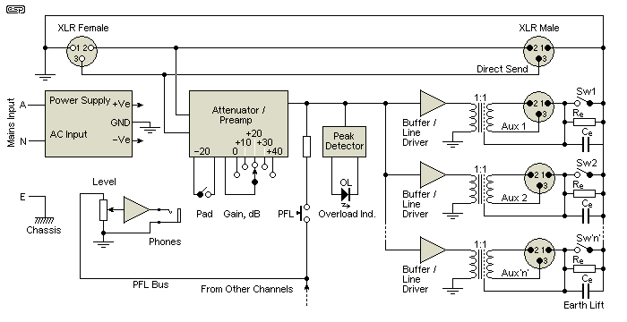
Figure 5 - Active Multi-Output Transformer-Based Splitter
Figure 5 shows the general scheme, but doesn't show the specifics of the gain, attenuation, peak detector or buffer stages. The peak detector is essential, because most of the time the person setting up the splitter won't know what gain is needed. Without the peak detector, the splitter's gain could be too high or too low and no-one would know until it got to the mixer(s). The PFL (pre-fade-listen) button allows an engineer to monitor the signal from each preamp, and while this helps ensure there is a valid signal, it can be difficult to detect clipping in a noisy environment.
Including the buffers has many advantages, because they ensure total isolation of each auxiliary send. However, it also means that a separate transformer is needed for each send, which can get expensive. The gain stage will ideally have switchable gain/ loss (attenuation), pre-listen facilities (so each signal can be monitored via headphones) and any other features desired. It's not difficult to include a detector circuit that will show if an auxiliary send is shorted or has very low impedance. I don't know of any professional system that includes this feature though.
The main send is the 'master', and is straight through as shown here. It can use one of the other sends of course, but then phantom power has to be included. A low noise preamp is needed, and ideally it will provide enough gain to ensure that all signals are well above the noise floor.
The splitter can isolate all the outputs if desired, and it's not difficult to include a sensing system that detects when phantom power is turned on at the master mixer, and turn on the P48V supply to the mic. If phantom power is supplied from any other mixer it should be ignored - only the master should be able to control the P48V system. Using transformers for each send means that if phantom power is applied when it shouldn't be, it will be ignored (or you could have a detector to trigger a warning light or even a siren if you wanted to  ).
).
A single attenuator and preamp is all that's needed for each channel of the splitter. Both have a comparatively high input impedance so the mic isn't loaded excessively, and although open-circuit noise (with no mic plugged in) is compromised, once the mic is connected the preamp in particular will be as quiet as any other mic pre. The circuit is not intended to bring the level up to +4dBV as may be used for 'line level' interconnections, but simply to provide enough gain (or attenuation) to ensure a clean signal to the auxiliary sends.
Note that each preamp shows 100k input resistors, and these are included to minimise switching transients when the attenuator is switched in or out. If the 20dB attenuator pad is not included, these resistors should be reduced to 10k.
two possibilities are shown below. Project 66 is a proven design that's fairly low cost but provides excellent performance. For this application it needs some minor changes because in its normal form it can't be reduced to unity gain (0dB). The modified version shown can run at unity gain with no problems. Note that the power supply bypassing isn't shown here, but it is essential that it's used.
Both circuits require input stage protection against phantom power, and a suitable circuit is shown in Project 96. Both also require a resistor network between the points G1 and G2. These set the circuit gain, and the networks use a different resistor string for each circuit because of different internal component values. A pot can be used for continuous gain adjustment, but in this application switched gains ensure that the gain can be set with good repeatability.
For Figure 6, with all gain switches open, the gain is close enough to 0dB (it's actually about -0.2dB). The gain setting resistors are Rg1 to Rg4. Rg1 (2.2k) provides gain of 10.3dB, Rg2 (560 ohms) gives a gain of 19.8dB, Rg3 (150 ohms) gives 29.6dB and Rg4 (27 ohms) gives a gain of 39.8dB. These gain values aren't exact, but it doesn't matter because the signal from any microphone varies widely in normal use.
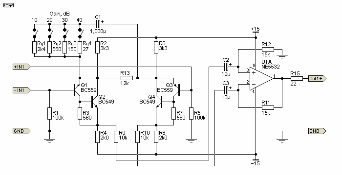
Figure 6 - Mic Preamp Based On Project 66
The second option is to use the INA217 (or the higher cost INA103 which is a little quieter, but needs different gain setting resistors). This is a straightforward circuit, and it looks very simple compared to the modified P66. However, because of the cost of the ICs it will almost certainly cost more (and I don't have PCBs available for the INA217 mic preamp). While it might not look like it, Figures 6 and 7 are functionally almost identical - the internal circuitry of the INA217 performs in exactly the same way as the Project 66 circuit.
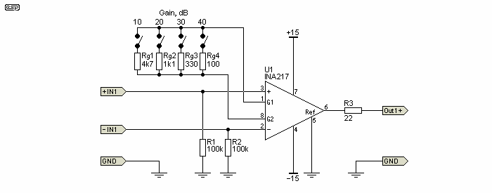
Figure 7 - Mic Preamp Based On INA217
In this version, when all switches are open, the gain is 0dB, Rg1 (4.7k) gives 9.8dB, Rg2 (1k1) gives a gain of 20dB, Rg3 (330 ohms) gives 30dB and Rg4 (100 ohms) gives 40dB. There are quite a few instrumentation amplifiers similar to the INA217, and many of them require different values for setting the gain. If you use something different, you may need to re-calculate the gain-setting resistors, and you'll need to see the datasheet to determine the values needed.
Adding an attenuator is a problem with these circuits, because it needs to have a high impedance to prevent loading the source and affecting the signal to the main mixer. Unfortunately, a high impedance attenuator will add noise, but one way of including an attenuator is shown below. It is a comparatively high impedance, but the signal level will be high too, so that may not be an issue. However, it will cause a problem if phantom power is used, because the attenuators would drain the available current, so C1 and C2 are included to prevent that from happening. Ideally, these would be bipolar capacitors, because there may be times when the voltage across them is reversed. However, this is unlikely to ever exceed around 100mV, and polarised caps can withstand that without failure.
The attenuator networks connect to the 100k input resistors of both mic preamps shown above. The four diodes (D1 ... D4) and associated resistors (R5 and R6) protect the preamp inputs from switching transients created when phantom power is turned on or off or when leads are plugged in or removed. This network is required in all cases, or the preamp will be destroyed!
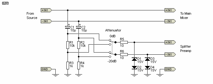
Figure 8 - Switched Attenuator
With most of the ideas shown here, because of the number of circuits, connectors, transformers (in particular) and switches they become expensive. A full system may require 24 or more channels, so unless you have deep pockets, building such a system will be painful. It goes without saying that buying an equivalent system will be even more expensive, so if you plan to put a reasonable PA system together, it might be worthwhile.
The benefits of building gear yourself are well known to anyone into DIY. In particular, you can build the system to do exactly what you need, rather having to accept a commercial system that may be lacking a particular feature that you require, or may have more features than are necessary for your particular application.
With any system that's out of sight of the sound engineer, it's necessary to provide independent clipping indicators. It is too easy for the gain to be set too high so that the remote splitter unit clips, especially if the gain is reasonably high. During the sound check, someone needs to verify that no clipping is evident on any channel. Because it's accepted that the occasional transient may cause clipping, the detector should be set for a lower voltage than might normally be used, so that the clip LED can come on every so often, but the signal will remain free of distortion.
The clipping detector needs to have a fast attack so it can pick up brief transients, and a slow release to ensure that the LED is on for long enough for the operator to see it. It can also be useful to have a 'signal' LED, that comes on to indicate that there is a live signal at the preamp. The threshold is generally arbitrary, but around -40dBV (about 10mV after the preamp) is a fairly sensible level.
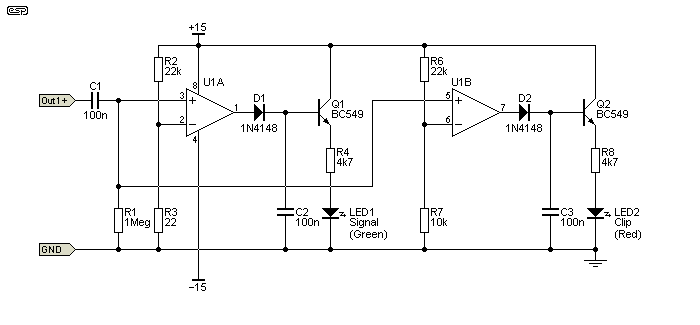
Figure 9 - Signal Present & Clipping Detectors
The detector input comes from the mic preamp. The opamp should be a TL072 or similar, which ensures a very high input impedance and low DC offset. The circuit shown isn't intended to be a precision detector, but it will reliably pick up the fact that a signal is present, and will indicate clipping if the peak input signal exceeds 4.7V (+13dBV peak). The peak detection threshold can be reduced by reducing the value of R7, which as shown sets the voltage at pin 6 to 4.68V DC. The detectors shown are half-wave and only work on the positive peaks. Full wave detectors can be used, but this adds cost and complexity but in this application is unlikely to be a major benefit.
It might be tempting to include compression if the signal exceeds the peak threshold, but this is uncommon and usually a bad idea. Excessive compression is already common, and adding a compressor that is independent of the main mix is not recommended. It's also rather difficult to accommodate so it includes the input preamp, and this is where clipping is most likely. It can be done using microprocessor control of course, but that will only add complexity and is one more thing to go wrong.
For some applications, it might be acceptable to use a transformerless balanced output. One place where this may be fine in practice is where the splitter has a send to a foldback mixer, which will usually be on stage and close to the splitters. They may even be in the same rack enclosure, so earth loops are unlikely is the system is set up properly. A suitable balanced output is shown below, and it's based on the circuit shown in Project 87. The main difference is the addition of output capacitors and the zener diodes. These are intended to protect the circuit from the accidental application of 48V phantom power from the connected mixer.
Active balanced outputs do not have galvanic isolation (so there is an ohmic path between all connected equipment), and this can cause havoc with earth/ ground loops. The capacitors might remove the resistive component, but they do nothing to remove the 'implied' earth that's created by all active systems. Each signal output is referenced to the ground bus of the source equipment, and a transformer is the only way they can be truly isolated. There are optical solutions, but they have comparatively poor performance against a transformer.
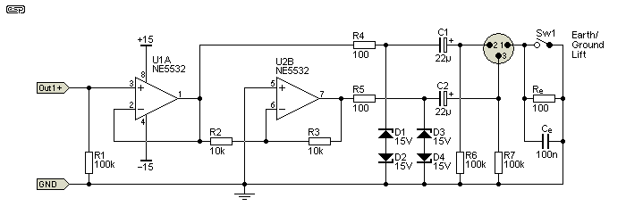
Figure 10 - Transformerless Balanced Output
Using a buffer can make a fairly ordinary transformer behave itself well enough to be usable over the full audio range. It is even possible (but not recommended) to use a negative impedance buffer that effectively counteracts the winding resistance of the transformer. This allows operation to lower frequencies and higher levels than would otherwise be possible, because a transformer driven from a zero ohm source generates zero distortion. See Transformers For Small Signal Audio for a complete description.
However, it's preferable to use a decent transformer to begin with, because it will create fewer problems and just makes your life that bit easier (albeit more expensive). Because transformers have a comparatively limited bandwidth, they also eliminate (or reduce dramatically) any RF interference that may be present. This can be an intractable problem if there isn't complete isolation between the interconnected systems.
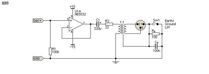
Figure 11 - Buffered Transformer Balanced Output
Assuming the use of a normal buffer to drive the transformer, you can use any competent opamp you like. NE5534/2, OPA2134 or LM4562 are all suitable, as are many others. Because of the very low DC resistance of a good transformer, DC coupling is not recommended, and the transformer should always be coupled via a capacitor. As noted in the reference above, the capacitor needs to be larger than you might think, and the final arrangement must be tested thoroughly over the full audio bandwidth to check for anomalies in frequency response, distortion and/or stability.
Resistor R1 is included in both of these circuits so each can be operated and tested in its own right, but if you were to need (say) 24 separate sends you'd be better off using FET input opamps and you can then increase the value of R1 to 1Meg. This reduces the load on the mic preamp, although even as shown (100k) it's not a difficult load to drive. The earth lift arrangement shown may not require the parallel resistor and capacitor, but this is something that must be tested with the transformers you use. As noted earlier, there are no rules here, but around 1k and 100nF should work well in most cases.
In many cases, splitters will be set up so that outputs can be combined, rather than using a dedicated '1-in-many out' configuration. This provides the maximum flexibility, but of course you may have lots of input gain stages that aren't used most (or all) of the time. A common arrangement is to include 'link' push-buttons that allow an input circuit to feed the next set of output sends. If all the link buttons are used, only the first preamp is active, with its output sent to all outputs. These may be on the front panel or rear panel (or both).
PFL (Pre-Fade Listen) can also be useful, so that inputs can be monitored with a pair of headphones to ensure that there really is a signal present, and not just noise picked up by a faulty lead or other source. The 'signal' LED shown above tells you that there's a signal present, but cannot differentiate between usable speech or music and noise. This requires a human to listen to the input(s). PFL has not been shown on the circuits above, except for Figure 5. The headphone amp can be a small power amp IC (such as an LM385) or a buffered opamp.
It should be readily apparent that ESP is not about to try to develop a project along these lines - this article is intended to look at options, problems and solutions, not to provide a complete system. Mic splitters and stage/ recording mixers are large and expensive projects. Project 30 has been available for many years, and a few hardy souls have made use of the info to build systems of varying size and complexity.
If you wanted to add remote control, you'll probably use relays to switch the gain, and to switch attenuators in and out as needed. This means that you have to use an existing remote control protocol or devise your own. Unless an addressing system is used, it will involve multiple cables. The only real solution to this is to use networked systems, where each splitter has an individual address and commands can be sent via a common signalling system to change the gain, activate or deactivate attenuators and/or phantom power, or even to switch individual sends on and off.
It doesn't take much thought to work out that such a system will become very complex, very quickly. Everything also needs a 'fail safe' setting, so that if communication is lost, the current settings are retained or fall back to a known (and hopefully usable) state. Commercial products exist that range from single transformer based splitters up to complex remote controlled multi-channel units.
While making the essential building blocks of a full-blown stage box with multiple sends is certainly possible, it's rather unlikely that anyone will be tempted to build their own, simply due to the cost involved. A stand-alone mixer is a comparatively undemanding piece of kit to build, but if your splitter is expected to be remote controlled, provide sends to a foldback mixer, FOH mixer, a live recording mixer or perhaps an outside broadcast van at the same time, it has to be bullet-proof. The essential principles are all described here, and the end result will likely be similar to many commercial offerings. Whether there is likely to be a cost saving is another matter entirely.
Yes, I could design a fully featured splitter that would satisfy most applications. No, I'm not about to do so  .
.
 Main Index
 Articles Index