
|
| Elliott Sound Products | Project 35 |
A Direct Injection (or DI) box is a very handy piece of equipment for any public address rig or recording studio, whether for live or studio use. It will allow you to connect the output from guitar/ bass amps, keyboard mixers, tape machines, CD players and just about anything else directly to the mixer, without using a microphone, and with no hum loops.
The unit described will convert unbalanced inputs (such as from a guitar or bass amp) to balanced, allows the level to be set to something reasonable, and comes in two flavours. There is a completely passive version that uses a transformer to create the balanced send, or an active unit which can be operated from a 48V phantom feed or a 9V battery.
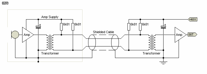
Firstly, for those who may not know about phantom feed, Figure 1 shows how it is done. The 48V supply in the mixer is connected to both signal lines, so it causes no current flow in transformers (since both ends of the winding are at the same DC potential). At the remote end, the current is tapped off the lines using a resistance value suitable for the electronics. Again, this is done with both signal lines to ensure that there is no DC imbalance in the circuit.

After filtering (and in some cases regulation as well), the DC is then available to power the circuit that drives the AC signal down the very same pair that provides the power. In all cases the shield must be connected at both ends, since this provides the DC return path (hence no earth lift switch). In this example a microphone has been used, but the same concept applies to virtually anything that can function on the limited power available. The maximum possible current from 48V phantom power is about 11mA, assuming a 10V supply for the electronics. Short-circuit current is 14mA.
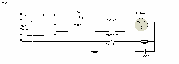
Figure 2 is the passive version of the DI Box, which is very easy to build. The only problem is that to get good sound quality, you will need a good transformer, and these are expensive. As can be seen, the input is simply two 6.5mm phone jacks to allow a speaker or line-level signal to pass through the unit. The output is a male XLR connector, and is balanced. Have a look at the Jensen Transformers (or any other audio transformer manufacturer) web site to track down a suitable unit. There are several other manufacturers, but availability can be patchy, depending on where you live. See if you can find one in your country. The transformer is 1:1 ratio, and needs to be rated for a minimum of 600Ω operation. The impedance itself is immaterial, but transformers intended for lower impedances will not have sufficient inductance to ensure low distortion at low frequencies. Ideally, the transformer will have at least 4 Henrys primary inductance so it will work properly from a range of source impedances.

The switch selects either line or speaker level from the phone jacks, and the 1k pot allows you to set the level when using a speaker source. When using speaker input, the attenuator is variable to allow for the widely differing output levels available from amps. An 'earth (ground) lift' switch is provided - these are often used to completely isolate the signal source, for those occasions where there is a hum loop created between the mixer and the stage equipment. There is also an earth isolation circuit (the 10Ω resistor and the 100nF cap), which will be more than enough except in the most extreme cases. The earth lift is only effective when a transformer circuit is used, and may prove worse than useless in an active unit (battery powered - you can't use a 'full' earth lift with a phantom powered DI box).
Before committing to a completely passive design, I suggest that you read Transformers For Small Signal Audio. In general, most users don't really understand how to get the best from any audio transformer unless they've been working with them for some time (between 'a long time' and 'forever'). While they appear to be simple (and in principle this is true enough), the reality is often different. For a good transformer, expect to pay rather more than you expected. Transformers (even expensive ones) prefer a low-impedance source, and performance is compromised if the impedance is greater than a few hundred ohms. The alternative is to use 'trick' circuitry as described in the linked article. This may not be feasible if you wish to operate from phantom power, as the available current is usually less than 10mA.
Note that jack sockets (¼" / 6.35mm) have been shown for signal input and output, but XLR connectors can also be used (wired for unbalanced mode). Pins 1 & 3 will typically be shorted together within the DI box. Jack sockets are more 'traditional', but are not ideal. Use the connectors that match the equipment providing the signal.
It's possible to include a JFET to drive the transformer and present a high impedance for the source, but if it's to retain the full isolation of a transformer, it has to be battery powered. A 'true' earth/ ground lift is not possible if phantom power is used, and ground loops remain a possibility, despite the transformer. This is an option that I may look at later, but it's not included here at present. Because of the cost of decent transformers, passive or buffered ('semi passive') DI boxes are fairly uncommon. Of course you can get them, but many will be very ordinary unless they are expensive - and even that doesn't guarantee you'll get a 'studio grade' transformer.
The active unit uses the 48V phantom feed available from many mixers, but can be run from a battery if this is not available. To ensure that there is no unnecessary battery loading a LED has not been included. You can add one, and if you do it should be a high-brightness type so current can be minimised. A 10k resistor will limit the LED current to around 700µA.
The connections to the XLR have been shown on all the drawings, and the pin numbers are clearly marked on the connector, designations are ...
Pin 1 Earth (Ground) Pin 2 Hot (+ve signal) Pin 3 Cold (-ve signal)
Note that in some cases (especially with older equipment of US origin), pin 2 is 'cold' and pin 3 is 'hot'. This connection scheme is not recommended, and should not be used. The above is as close to an official standard as you will find, and should be used in all cases.

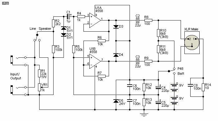
An earth lift switch cannot easily be used with phantom powering, and has not been included. The 10Ω resistor and 100nF cap should be quite sufficient in all but the most stubborn of cases. R14 can be increased, but more than 100Ω isn't recommended. The value of R10 and R11 can be reduced to get more voltage for the opamps. I don't recommend less than 3.9k, as anything lower will stress the opamp outputs and cause distortion. In theory, the input can be up to 2.5V RMS, depending on the opamp supply current (the 'typical' value is around 2.5mA for the 4558 IC [two opamps]).
The opamps require protection from the applied 48V when the unit is connected, and this is provided by the diodes from the opamp outputs back to the power supply. Without these it is possible to damage the opamps as the output capacitors charge. Because some degree of mucking about would be normally be needed for the output capacitors to make the unit truly universal, these are specified as bipolar (non-polarised) types - standard electrolytics must not be used if you include both P48 and battery power. You can use 2×47µF caps in series (negative pins joined) to make you own bipolar cap if you can't find non-polarised types.
If the battery option isn't needed, C2 and C3 can be polarised electros, with the positive terminal to the outputs. This is likely to be the preferred option in most cases, but including battery power is likely to be useful for live work. Note that a 'power-on' LED has not been included, as the available current is already limited. You could use an ultra-bright LED with (say) a 10k limiting resistor, but with a current of only 600μA or so, don't expect it to be highly visible.
All resistors should ideally be 0.5W 1% metal film for lowest noise and best matching. Capacitors must be rated at 35V or more, and the diodes are 1N4148 or similar. The zener diodes will normally be 0.5W or 1W types. D3 and D4 help to protect the opamp outputs if phantom power is used (intentionally or otherwise). If a cable is plugged into a mixer with P48 turned on, the cable capacitance charges to the full 48V, and the discharge current will be very high when the DI box is connected. The diodes prevent the high current spike from causing damage.
It is possible to use a TL072 opamp, but the suggested device is preferred. The 4558 is quite happy with a supply voltage as low as ±3V, although the output level is very limited with such a low voltage and an 18V battery supply is highly recommended. The 4558 opamp has been a mainstay of guitar effects pedals and budget mixers for a very long time, and it's a much better opamp than most people give it credit for. It doesn't come close to 'premium' opamps of course, but it's been selected because it has low current consumption and it can operate from a single 9V battery. There are other possibilities for the opamp, but the total supply current should be less than 5mA to get the maximum output level without distortion.
Higher signal levels can be achieved with two 9V batteries, and as shown the DI box can handle up to 2V RMS input with phantom or battery power. This is reduced to 700mV RMS (0dBm) with a single 9V battery.
Two versions of the active unit used to be shown here, but by using bipolar output caps and protection diodes the unit can be dual-purpose. When plugged into a phantom supply, make sure that the switch is in the phantom position to eliminate unnecessary battery drain. Likewise, always leave the switch in the 'Phantom' position when not in use. This disconnects the battery.
If you want to make the unit phantom or battery only, simply leave out the parts that you don't need. For battery only, you don't need R10 and R11, and D5 (24V zener) can also be omitted. If the unit will only be used with phantom, then you can omit the Phantom/ Battery switch and the battery/ batteries.
 Main Index
 Projects Index