
|
|
| Elliott Sound Products | Benefits of Bi-Amping (Not Quite Magic, But Close) - Part 1 |
 Main Index
Articles Index
Main Index
Articles Index
Firstly, it must be understood by the reader that this article was first published in 1998, well before active speakers were even known to the majority of the public. At the time, only a very few active speakers existed, and they were predominantly reserved for the most esoteric of applications. There were virtually none available from any established manufacturer, and the very thought of having power amps co-located with speakers (often within the same enclosure) was not considered. I built my first active speaker system (a PA for use with a band) in around 1970, and at the time it was quite possibly the first such system ever sold.
Active speakers are still uncommon, with the vast majority of hi-fi systems still using separate amplifiers and passive crossover networks. These have been the mainstay of home hi-fi for so long that active systems are often viewed with suspicion - some owners like to think that they can change power amps to 'change' the sound. This is (despite the many claims to the contrary) almost completely untrue. Very few power amplifiers will sound any different from their peers in a properly conducted double-blind test. Valve (vacuum tube) amplifiers are an exception!
One of the greatest advantages of biamping (or multi-amping) is that the power amps can be optimised for the task, allowing a potentially significant reduction of heat because a single amp doesn't have to be able to provide power over the entire audio frequency range. Smaller amps can be used for tweeters because they don't need as much power as woofers or midrange drivers. These topics are all covered below (and continued in Part Two of this article).
Active speakers don't necessarily have to have the power amps built into the speaker cabinet, although commercial products almost invariably do so. They are now readily available for PA and sound reinforcement, studio monitors and 'true' hi-fi. When you build your own system using the designs featured in the ESP Projects, you can put a system together that does everything you decide is necessary, and in the manner that you prefer.
Although this article concentrates on biamping, with the top end still handled by a passive crossover, there is no reason not to (and many reasons to) use a 3 or 4-way electronic crossover, so that each loudspeaker driver has its own dedicated power amplifier. My home hi-fi is set up as a 4-way active system, using separate amps for the subwoofer, woofer, midrange and tweeter. Even my workshop system is 3-way active. A full 4-way active system is my recommendation, as it provides the best possible performance from any set of drivers.
Fully active speakers are now starting to enter the mainstream, with offerings from many different manufacturers. They have still not been completely accepted by many audiophiles, but the benefits are so compelling that it's extremely hard to justify the time and expense needed to design and build a passive crossover network that can even come close to the performance of even a basic electronic solution. I would never revert to a passive system for serious listening, and most people who have made the transition using my projects feel the same way.
The terms active, passive, powered, and un-powered are often used incorrectly, and in some cases they may (incorrectly) be used interchangeably. It's important to know what, specifically, is being addressed when someone uses any of these terms. Even specifications can be misleading if you don't know what to look for.
Even the term 'passive crossover' is sometimes misused. Some systems have nothing more than a capacitor for the tweeter. This is not a crossover - it's usually an abomination. The arrangements described in this article (and Part 2) refer to active systems, where it's up to the constructor to decide where the amps are situated. Mine are separate from the enclosures, as are most of the systems built by people using ESP projects.
Most people would tend to think that biamping a hi-fi system (or even a sound reinforcement system) is unnecessary, or only for the most powerful systems. This is not the case, as the following article will attempt to demonstrate. There are very real advantages to using bi-amplification instead of the standard arrangement we commonly use, where one power amplifier must drive all the loudspeakers in the enclosure, along with the typical passive crossover network which can - at times - have a mind of its own!
If you are in a position to spend $25,000 or (much) more for a pair of speakers, then this is approaching the 'cost no object' arena, but the majority of people cannot afford such luxuries, and must settle for something a little more pedestrian. As a result, very few systems will be as good as they can be. Biamping is not a simple tweak, and is not to be taken lightly.
Make no mistake though, its application will improve almost any loudspeaker available, with very few exceptions. The optimum is a fully active system - 3-way or 4-way electronic crossovers, and a separate amplifier for each loudspeaker driver. To buy such a system was once extremely difficult, but it's quite easy for any DIY enthusiast to implement. Commercial fully active speaker systems tend to be very expensive, but the DIY approach provides a great deal of flexibility and is (comparatively) cheap to implement.
ESP has sold a vast number of electronic crossover PCBs (and power amps to go with them) over the years, and the results obtained based on customer emails are always better than expected. Most constructors are astonished at the end results, and the Net is now full of information about the use of active systems. When this article was first published in 1999 there was almost nothing about the use and benefits of active systems for home hi-fi. How times have changed. 
For what it's worth, by own system is 4-way active, using separate power amplifiers for each speaker driver. There is a subwoofer, stereo woofers, midrange and tweeters, so seven amplifiers are used in all. The electronic crossovers are early versions of the Project 09 and are 24dB/ octave, Linkwitz-Riley alignment. It's been in daily use since around the turn of the century (that makes it sound really old).
Note
Some of the terms used in the descriptions of various design configurations may be registered trade marks. These terms (where used) are not to be taken as a reference to any particular product, company or corporation - they are used only in their generic or common technical sense and infer no affiliation with any third party.
The following is a technical article, and is not an attempt to sell any product, although ESP does sell PCBs for electronic crossovers and power amps. It is informative and all ideas herein are a combination of common knowledge (and sense), and/or my own thoughts on the subject. No reference material is quoted, since none was used (other than computer simulation of various filter types to ensure that I am not speaking through my hat).
Biamping is a technique which uses one amplifier for the low frequencies, and another for mid and high frequencies. The choice of crossover frequency is not too critical, provided that the amplifier powers are properly balanced to achieve the maximum benefit, and the drivers used are operating well within their frequency and power limits.
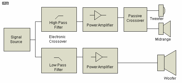
Figure 1 - Biamplification Block Diagram
Figure 1 shows the basic concept in block diagram form. Only one channel of the stereo pair is shown, the remaining channel is identical. Note that the midrange to high frequency crossover retains a passive design - more on this later in the article.
In a simple form (using really simple electronic crossovers and little amps) biamping can be used even for computer speakers, clock radios and the like. The cost of the little amps is low, and the sonic improvement can be quite dramatic. I used to have a sub-woofer on my clock radio (really) and it actually sounded quite decent - at least insofar as a clock radio can sound decent.
As a solution to just about any amplifier-speaker combination, biamping has to be the way to go. At the highest or lowest ends of the audio equipment range, a biamped system will sound better than conventional passive crossovers, and one amp doing all the work.
The most common question I get is ...
"Do I need to disconnect the passive crossover in my speakers?"
The answer is ... Yes, otherwise you are not really biamping at all.
Generally speaking, the mid to high section needs to be retained since a typical biamp setup will only eliminate the bass to mid+high network. These sections are nearly always completely separate networks, although it may not seem like it when you first have a look at the board. The alternative is to go fully active, which means three amplifiers per channel for a 3-way system. Then, all passive networks are removed from the system. While this might seem like overkill, it will provide the best possible performance. 4-way systems can also be done, either by adding a subwoofer, or by building or adapting two fully active 4-way speaker systems.
Equally important is the selection of the electronic crossover frequency. It must be the same as the original, within a few 10s of hertz. The only exception is where you might obtain information from the manufacturer of the speaker that allows the frequency to be modified. In general, I strongly suggest that you determine the original crossover frequency, and stay with it.
When the crossover is modified, make sure that you retain all the parts, along with the original connections. A drawing (including all component values) and photograph will be of great assistance when you want to restore the speakers to normal prior to selling them - it is unlikely that you will ever want to do this for your own use - not after you have enjoyed the benefits of biamping for any length of time.
Passive biamping (where two amplifiers are used in a bi-wiring connection) is, IMO, a waste of money. Although there may be some moderate sonic benefits, they are not worth the expense of the extra amplifier.
In writing this article I have endeavoured to keep technical terms to a minimum. Unfortunately, this is quite impossible (for me anyway), so if you are not familiar with the terminology used, please refer to the Glossary of Terms, now in a separate page.
This includes some terms which are not in the body of the article, but are useful nonetheless since they may be encountered elsewhere.
Initially, let us look at an 'ideal' situation, where the loudspeakers for low and midrange plus high frequencies have the same sensitivity (say 90dB / watt @ 1 metre). This means that in free space (without reflections from walls etc.), the speaker will provide an output of 90dB SPL (Sound Pressure Level) measured at a distance of 1 metre with an input power of 1 Watt. This will usually be measured with band limited noise, so the speaker's little peaks and dips will not overly influence the measurement.
The high frequency driver (tweeter) is of minimal interest at this point in the discussion, so will simply be lumped in with the midrange to give mid+high.
With typical program material (whatever that is), it has been determined that the 'equal power' frequency between low and mid+high is between 250Hz and 350Hz. This is defined as the frequency where the bass and mid+high amplifier power requirements are equal. So with our 90dB/Watt/Metre speakers above we could assume that 100W amplifiers might be appropriate.
This will allow an absolute maximum of just over 110dB at one metre. You may think that is loud (you would probably be right, too), but this is the peak single-frequency SPL, and allows for transient signals - ensuring that at no time does the amplifier clip (cut-off the tops or bottoms of the waveform). This introduces distortion which quite apart from sounding awful, causes listener fatigue and places loudspeaker drivers at risk of damage.
The Speaker Damage popup has more information on this topic for those who are interested. In addition, it is suggested that you look at the article Why Do Tweeters Blow When Amplifiers Distort? for further details
The actual (averaged) SPL at one metre will be somewhere in the vicinity of 90 to 100dB, depending upon the program material. The average SPL at the listening position cannot be determined without complete analysis of the room's acoustics (for a typical room you will lose another 6 to 10dB), so for simplicity we will use the 1 metre SPL as a reference value.
Thanks to a reader, here is a small table that shows the power distribution at different crossover frequencies. The table came from a loudspeaker manual 'LOUDSPEAKER ENCLOSURE DESIGN AND CONSTRUCTION' published by FANE.
| X-over Frequency (Hz) | Power to Bass (%) | Power to Mid+High (%) |
| 250 | 40 | 60 |
| 350 | 50 | 50 |
| 500 | 60 | 40 |
| 1,200 | 65 | 35 |
| 3,000 | 85 | 15 |
| 5,000 | 90 | 10 |
Note that according to this table, the equal power point is 350Hz (which I calculated, since it was left out of the original). This is slightly different from my own measurements, but the error is of no consequence, regardless of who is right. As can be seen, the power requirement falls quite rapidly after 1200Hz, and although not shown, it also falls off with reducing frequency.
Since the last statement will possibly cause some discomfort or indeed confusion (after all, everyone knows that a subwoofer needs more power than the main speakers), I should explain myself. Most of the time in this article, I refer to power as average power, and indeed the average power falls with frequency below about 100Hz or so. The peak power is a different matter, and depends to a very great degree on the type of music.
The table assumes equal efficiencies for the bass and mid+high drivers. Should they be different, then a correction factor must be added in. For example, if the bass driver were to be 3dB less efficient than the mid+high drivers, then the bass power must be doubled (and of course vice versa). If the difference is less than 3dB, you may safely double the power anyway, or calculate the actual power needed - this I shall leave as an exercise for the reader.
This is a very important point, and cannot be over-emphasised. Some subs (particularly those using the 'Extended Low Frequency' ELF™ technique) will need a huge amount of additional power at the bottom end because of the way they are driven. It is not easy to give a simple formula (so I'm not going to  ) to calculate the power needed, because there are so many variables.
| Do not be tempted to reduce bass power below about the 40% level regardless of crossover frequency, because although the average power might be quite low, it is usually of
relatively high peak amplitude. The wide dynamics of the bass content require an amplifier capable of far more power than might be imagined if clipping is to be avoided. Clipping
is something that one should avoid at all costs, because apart from sounding horrible, the average power level is increased, placing loudspeakers at risk. Having said that, some
peak clipping in a subwoofer may be inaudible, provided the remainder of the signal is clean. In general, I suggest that the bass amplifier should have at least the same power as that used for the mid+high frequencies, but if any equalisation is used (such as the Project 71 Linkwitz Transform circuit), this may need to be increased dramatically. A boost of only 6dB at (say) 30Hz may require that amp power be increased by 4 times. |
If we assume that our 100 Watt amplifiers will be handling exactly the same peak amplitudes with typical program input, then we have a total of 200 Watts for the combined program material. So, where does the magic come into this? This amp combination will sound (and measure) as if it were 400 Watts - twice as much 'effective' power as there is real power. This is a highly simplified explanation though, and you may or may not realise the full benefit depending on a great many factors. For this to make sense, we need to back track a little.
Imagine a sine wave signal of 100Hz at an amplitude of 28V RMS. For an 8 ohm load, this equates to about 100W (98 actually). The same amplitude at 1000Hz will be exactly the same power. Now add the two signals together, in the same way that signals add together in music. We are interested only in the peak amplitude, the RMS value indicates that the power is only 3dB higher, but it is only when an oscilloscope is used that the true picture emerges.
We will now see a low-frequency waveform, with a higher frequency waveform superimposed - the high frequency signal will be riding up and down the path of the low frequency signal. If we were to perform a calculation (or simply measure the combined signal with an oscilloscope), we will see that the peak amplitude has doubled. The effective RMS value (most multimeters will get this wrong unless they are true RMS types) is 40 Volts, and this would imply 200W. Although this is the real RMS voltage, it totally underestimates the amplifier power needed to reproduce it cleanly. An oscilloscope shows 80V peak for the same waveform, so the amplifier must be capable of passing an 80V peak signal - a 400W amplifier.
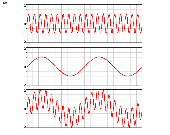
Figure 2 - Addition of Waveforms
To illustrate this point, Figure 2 shows two signals, each of 1 Unit peak amplitude. As can be seen, when the two are combined, the amplitude is much greater. The maximum peak amplitude is now 2 Units - double the peak voltage and four times the peak power of each signal individually. Power increases as the square of voltage, so twice the (peak) voltage is four times the power. Real ('RMS') power increases by 3dB or double the power, but this is a misleading figure and cannot be used. An oscilloscope is essential because amplifier clipping depends on the peaks of the signal, not the RMS value.
Note: Peak-to-peak amplitude is actually double the values quoted above, but since amplifiers are generally symmetrical (capable of equal positive and negative voltage swings) it is more convenient to simply refer to the peak amplitude only.
This is not to say that the actual music will be symmetrical. It isn't, but it is completely unpredictable in nature. As a result, it is possible (for example) to set up an amplifier asymmetrically and adjust the phase to suit with a switching circuit, since it will change. AM radio actually does this (or they used to) - a circuit is used to switch the phase so that slight over modulation causes more transmitter power, but never reduces it below the acceptable minimum. I shall not be going into details, since I believe few audiophiles would find this acceptable - I know I wouldn't.
All signal sources have the same characteristics as shown above in Figure 2, even a solo voice or musical instrument. In these cases, the fundamental frequency forms the low frequency component, while the harmonics 'ride the wave' as it were. Not surprisingly, the 'equal power' frequency will change (often dramatically) from the 250 to 350Hz range quoted above, but the basic principle does not alter.
Completely beside the point (but interesting anyway) is that in many musical instruments, the harmonics are actually at a greater amplitude than the fundamental. (File this away under 'Useless Information'.)
Note: It must be explained here that the 3dB effective power increase is the absolute maximum that can be obtained. In most cases it will be less - I have examined sections of music where the power gain was less than 1dB, and it can be reasonably safely assumed that the real gain will lie somewhere between 1-2dB in most cases. The real figure depends a lot on the type of music, the actual crossover frequency, and the peak to average ratio of the two separated signals. Just this topic alone is sufficient for a complete article in its own right.
A passive crossover will separate the two signals shown above and feed each to the appropriate loudspeaker in the system. The amplifier must be capable of handling the entire composite waveform, so for our previous example of 100 Watts for each signal individually, must be capable of 400 Watts to reproduce the waveform without distortion.
If we now we separate these signals again - prior to the power amp - and using an electronic crossover, we have an entirely different situation. (Note: It is assumed for the sake of this article that the crossover frequency is near the halfway point between the two discrete frequencies of Figure 2.) Each signal is now supplied to its own 100W amplifier (there will be but a hint of the other frequency still visible on an oscilloscope, since the filters are not 'perfect') and thence to the loudspeakers. The amplifiers are not clipping, both signals are reproduced at their original power, and the effective result is that we are emulating a 400 Watt amp with two 100 Watt units.
By way of comparison, the waveforms in Figures 3A, 3B and 3C show what happens if the composite waveform is fed into a single 100 Watt amplifier, and we try to obtain the same power output as before. Once the amplifier's output voltage attempts to exceed the internal power supply voltage, the amplifier clips the tops and bottoms of the waveform - resulting in harsh distortion and placing tweeters at extreme risk due to the additional high frequency energy which is created by the sharp transitions of the clipped waveform, and even more so by the compression of the signal (see Speaker Damage). This also adds a considerable amount of intermodulation distortion to the signal, so the distortion is not just harmonic, but can also be discordant (not harmonically related). This is the worst kind of distortion, and sounds really gross.
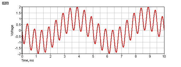
Figure 3A - Unclipped Waveform Expected from 400W Amplifier
Using the same principle outlined above, we add a 200Hz signal and a 2kHz signal, each having 1 unit (1V) amplitude. The result is a combined signal with a peak amplitude of 2 units. Again, if we equate 1 unit (1V) with a nominal 100W, then 2V is 400W.
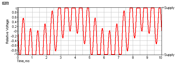
Figure 3B - Clipped Waveform From Underpowered Amplifier
The result of feeding a 2V input signal into an amplifier that is capable of reproducing 1V is shown in Figure 3B. The waveform in Fig 3B is exactly the same as that in Figure 3A, except the amplifier has limited the peak amplitude to ±1V, so causing the signal to be clipped. It is not immediately apparent, but both the low and high frequencies are distorted by the clipping action, and it is obvious that a significant part of the signal detail is no longer available as it has been 'clipped' off.

Figure 3C - Spectrum of Clipped Waveform
It is quite obvious that some of the signal has gone missing because of clipping. Not so obvious is that additional new frequencies are created, and this is shown in Figure 3C. This is a spectrum of the clipped waveform. The normal (unclipped) spectrum simply shows two peaks - one at 200Hz and another at 2kHz, with both being exactly 1V in amplitude.
Figure 3C shows that there is a multiplicity of 'new' frequencies. The original frequencies are each reduced to 714mV, and new frequencies are added. We have simple distortion, adding 600Hz to the signal, as well as sum and difference frequencies. These add 1.8kHz and 2.2kHz (at over 10% distortion level), as well as 3.8kHz and 4.2kHz. 6kHz is added (the third harmonic of 2kHz at the same level as the new 600Hz signal), plus 7.8kHz and 8.2kHz. All of these signals are above 10mV in amplitude (1% distortion referred to 1V), but there are a great many more new frequencies below that level. The end result is a very harsh noise - it no longer qualifies as wanted sound (or music).
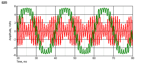
Figure 3D - Clipped Waveforms - LF & HF
Figure 3D shows exactly what happens to the HF signal. There is severe amplitude modulation on the red trace (1kHz) based on the (moderate) clipping shown on the full-range signal (50Hz + 1kHz, 4:1 ratio, green trace). The red trace has been amplified so it's easier to see, and the effect is very clear.
While it may seem that a biamped system gives you 'something for nothing' in the power department, this is not really the case. Four 100 Watt amps (2 x stereo 100W / channel) are going to be about the same price as (or perhaps more than) two 400 Watt amps (1 x stereo 400W / channel), but they will not be as highly stressed by high voltages, will probably run cooler, and each only has to handle a more limited frequency range. (For more good ideas on this concept, see Summary, below.). An electronic crossover is also needed, and this adds to the total cost of the system. Of course, the low frequency passive crossover isn't needed, so this offsets the overall cost somewhat. While you never get something for nothing, biamping probably comes as close as you'll get.
The basic principles described above also apply to the way high frequency signals are superimposed upon the low and middle signals. The main difference is in the energy (power) of the respective frequency bands. There is normally a relatively high amount of energy in the midrange band (see Crossover Frequency Selection in Part 2) as well as in the low frequency band. However, as the frequency increases beyond the upper fundamental frequencies of most musical instruments, the amount of energy falls off. Typically this will occur from about 800Hz and up (but will vary widely depending upon the type of program material), and the energy content will be seen to drop at a rate of about 3dB per octave (and more rapidly again above about 5kHz).
Since with a 3-way system the midrange to tweeter crossover frequency will be at perhaps 2500Hz or so, we can expect that the energy content of the high frequency band will be 9dB to 12dB down compared with the low and mid ranges. If we translate that back to our original 100 Watt amplifiers, this equates to somewhere between 7 and 12 Watts (peak) - giving an average power of around 1 Watt.
Because the high frequency energy content is such a low value (about 1/10th that of the midrange band), there is not a lot to be gained by using another electronic crossover network to separate this from the midrange signals. If the goal is to obtain the absolute maximum SPL (such as for sound reinforcement) it will be well worth the effort, but for hi-fi the law of diminishing returns indicates that it is not generally worthwhile. However, for optimum clarity, there is no comparison. An electronic crossover is not affected by driver impedance, and is (comparatively) infinitely stable.
One area where it is certainly better to use the additional electronic crossover and more amps for the tweeters, is where the sensitivities of the midrange driver and tweeter are more than 2 or 3dB different. In this case, using a separate amp will allow the levels to be matched far more easily, and will eliminate the use of resistive pads in the crossover network. There is also the potential for a useful reduction in intermodulation distortion, although with good quality modern amplifiers this is normally very low.
Intermodulation distortion in an amplifier is a form of distortion created when two different frequencies are being amplified simultaneously. The effects of intermod are most noticeable when one of the frequencies is much lower than the other, and the high frequency signal is actually modulated by the low frequency. This is quite different from the signals simply adding as they are supposed to. The effect (musically speaking) is that the sound is muddied, and the highs lose their transparency. Individual instruments become difficult to separate as their harmonics all start to blend into a 'wall of sound' (have another look at Figure 3B - this is intermodulation distortion at its worst).
As described above, intermodulation distortion is not harmonically related, so its effect is worse than simple harmonic distortion. Transient Intermodulation Distortion (TIM or TID) is (supposedly) created when fast transients exceed the amplifier's ability to change its output voltage fast enough. Although uncommon in modern amplifiers, TIM is still theoretically possible, although it is very rare to find any programme material that will cause any reasonably competent amplifier any stress.
These effects can be hard to quantify, but by using two (or more) amplifiers, any problems will be greatly reduced.
By separating the low and mid+high frequencies from each other prior to the power amplifiers, we reduce (to a large degree) one of the major sources of intermodulation. This is a great benefit to the music lover, since the sound instantly becomes more open and cleaner.
 | So far we have identified two major plusses - effectively more power, meaning that transients are less likely to cause amplifier overload (clipping), and reduced intermodulation distortion. But wait, there's more .... |
For those who are unfamiliar with the setup of a three-way passive crossover, please refer to Figure 5, which shows (and the text explains) the connections. The diagram shown is for a 'bi-wired' system, but includes the conventional connections.
When an amplifier reproduces the entire musical range, coils (inductors) and capacitors are used in the speaker cabinet to separate the high and low frequencies so that each may be supplied to the appropriate loudspeaker driver. A loudspeaker can be a difficult load for any amplifier, but when additional inductance and capacitance enter the equation, this often makes matters worse. Add to this the fact that all passive crossovers introduce some degree of loss (in some cases as much as 3dB - which means that they are 'stealing' half the available power), and one can see that getting rid of them cannot be such a bad thing.
Look at the impedance graphs for almost any speaker system, and it will be seen that there is almost always a dip in impedance (sometimes severe) at the crossover frequency. This is caused by the interactions of the loudspeakers and their inductor/capacitor networks, and in some cases can cause amplifiers considerable grief - especially at high power levels. Although few amps will fail, one can expect a reduction in effective output power as the protection circuits limit the maximum power available due to the loading of the crossover network.
These vague thoughts are brought into stark reality when one learns that the inductors and capacitors needed for the low frequency crossover are quite large values, which leads many speaker designers to compromise in the interests of economy. The inductors may have an iron or ferrite core - which improves its inductance, but ruins its linearity. So now the crossover behaves differently depending upon the amplitude of the signal. High value high quality capacitors are expensive, so again, bi-polar electrolytics are often used. It is often stated that these sound awful, although this is a somewhat contentious issue, but without any doubt their characteristics change with temperature and age. They also have rather mediocre accuracy against their claimed value (+20/-50% is typical), so a 10µF crossover cap may be 12µF, or as low as 5µF. However, it must be noted that they are usually much closer to the claimed value than the tolerance would imply. The poor tolerance and aging characteristics don't not make for an accurate crossover network though, and most reputable speaker manufacturers will not make this sort of compromise, at least not for their top-of-the-line models.
In addition, at high powers, the impedance of the voice coil rises because of the temperature rise in the voice coil. This is not stable, and varies widely with the music. So with loud passages, the voice coil temperature might rise significantly, which will severely impact the performance of the crossover - relying as it does on the load impedance being a constant. A loud bass solo followed by a relatively quiet but complex passage might create an interesting shift in the crossover frequency and phase response as the voice coil cools, which is unlikely to enhance the listening experience.
In contrast, the electronic crossover uses active filters in the low-level signal path. These suffer none of the 'power eating' problems of the passive variety, and are far more easily tuned to exactly match each other - both within the same unit (between low and mid+high), and from one unit to the next. Indeed, it is so easy to tune an electronic crossover that they could be (and often are) set up individually for the exact loudspeaker drivers installed in a given cabinet.
In the sound reinforcement industry, crossover frequencies may (or should) be changed to suit the type of music, or even to suit the acoustics of a particular venue.
There are no issues with the crossover frequency shifting, since it is stable and not at all reliant on the voice coil impedance. This will still change with the power level, but the effects are unlikely ( or at least less likely) to be audible.
| | Now there are another two plusses to add to the list - elimination of the low frequency passive crossover, resplendent with its inherent losses, potentially poor linearity and crossover point inaccuracy (either as manufactured or with time, or both), and the reduction of the difficulty of the load presented to the power amplifier. Both of these result in more effective available power, ensuring that transients are preserved and overall linearity is improved markedly. |
This rated a brief mention above, but is a highly contentious issue and can cause (does cause?) many a fine speaker system to suffer from a relatively low overall sensitivity. When a speaker manufacturer chooses drivers for an enclosure, they should be the very best available for the intended final product. In many cases, although other characteristics may be ideal, the chosen drivers will have different sensitivities. This is generally solved by 'padding', using resistive dividers to reduce the sensitivity of the more sensitive driver to match that of the least efficient. So if our hypothetical drivers (as described above) were to have the following efficiencies:
It is immediately apparent that the midrange loudspeaker requires only half the power of the low frequency unit for the same output SPL. (It is 3dB more efficient, and 3dB equates to half (or double) the power.) This will never do for a quality unit, so it must be padded back by 3dB if the midrange is not to be prominent. Likewise, the efficiency of the tweeter is also too high, so this must be padded by 2dB to bring it into line with the others.
This represents power being thrown away, simply dissipated as heat in resistors in the crossover network. But wait! Amplifier damping factor is a much quoted and highly sought after commodity. It mainly affects the low frequency drivers, but midrange loudspeakers are just as likely to have their own little resonances, too. Admittedly, these are much easier to control than the low frequency nasties, but it does seem to be such a shame to use all that expensive cable to ensure the best possible response and damping factor, and there it is - gone - filched by a couple of resistors (pretending to be inductors).
Oh, and speaking of resistance. Remember the inductor for the low frequency crossover? Well the resistance of that is probably between 3 and 20 times greater than the resistance of your expensive cable - assuming of course that you believe in the cable nonsense on the Net. Don't assume that bi-wiring helps this either, because it doesn't (more on that a little later).
With our biamplified model, we can simply adjust the relative gain of the amplifiers (and their power too, if maximum SPL is the goal) to bring everything back into balance. No power is lost as heat in redundant passive components, and we can ensure that the damping factor of both low and midrange drivers is not compromised by the crossover components. The low frequency loudspeaker in particular is driven directly by the power amplifier with only the speaker cable in between. By using an amp with 3dB more power for he woofer (double the power) the woofer and midrange are now equalised. The tweeter amp is of no consequence in terms of power, since the input to the tweeter amp can simply be reduced by 2dB.
There are also some loudspeaker drivers that, for various reasons, will sound better if driven from a finite impedance. This may be to correct the Thiele-Small parameters, or (as has been suggested by one reader who referred me to a web site - in Russian) to reduce driver intermodulation distortion. This is an area that I may investigate at some time, but I have been using this technique for many years. If a driver is installed in a box that's a little too big, the Thiele-Small parameters can be electrically corrected by using an amplifier with a carefully defined output impedance.
For more information on matching the amplifier power to the speakers, see Correcting Crossover Filter Amplitude Response, below.
| | Add two more plusses. No padding is required to align the driver sensitivities, so we are not simply wasting power, and the damping factor is greatly improved for both the low and midrange loudspeakers (or can be individually set to the impedance that makes the speakers the happiest). |
This one is nearly as big a 'killer' as the power gain - and from a musical point of view it may well be seen as even more important. The phase response of any crossover is quite predictable, as long as the source and load impedances are well defined and stable. In a passive crossover, this is rarely the case, and the results can be quite nasty. There is a phase transition around the crossover frequency, and with 12dB/octave filters there is a phase reversal between the low frequency and the mid+high frequency outputs. This can be seen if one examines the wiring of a speaker using a 12dB crossover network, and it will be observed that the midrange driver is wired out-of-phase with the woofer. The same thing happens with the mid to high crossover, except that the tweeter is now back in phase with the low frequency driver. Note that 24dB/octave crossovers not suffer a phase reversal.
It must be noted that the phase reversal is required only to ensure that the drivers are in phase at the crossover frequency. A couple of octaves each side, and with the inductive and capacitive load presented by a loudspeaker, the signals may be out of phase to a greater or lesser degree due to the impedance variation with frequency of the drivers.
See Project 09 for a Linkwitz-Riley aligned 24dB/octave crossover that is phase coherent, and has the added benefit that there is exactly equal power at all times from the two drivers. A conventional (Butterworth) crossover by way of comparison has a 3dB peak at the crossover frequency when the two outputs are summed.
Figure 4 shows how the phase reversal in a 12dB/octave crossover comes about. At the crossover frequency, each waveform is subjected to a phase shift of 90°. Since one is positive (called 'leading' phase) and the other negative (lagging), the net result is that the two waveforms are 180° apart - exactly out of phase. Notice that at frequencies significantly lower than the low-pass filter's cut-off frequency (defined as the -3dB frequency), there is little phase shift at all. The converse applies to the high-pass filter, so at significantly higher frequencies there is again little phase shift.
This gives rise to the phenomenon described above, where the driver phase reversal is needed to prevent massive cancellations at the crossover frequency. The cancellations will occur at other frequencies too, but are not audible because the level difference is so great.
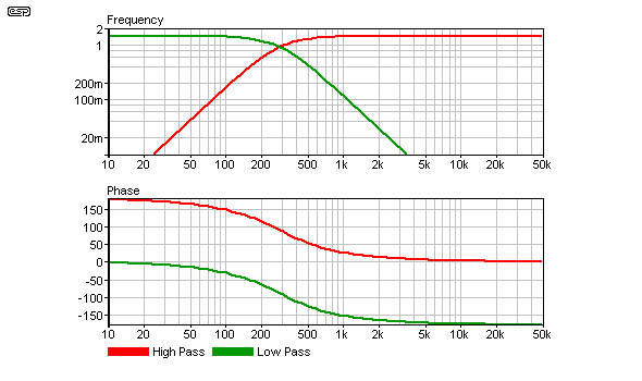
Figure 4 - Frequency And Phase Response of 12dB/Octave Crossover
It has been demonstrated by many workers in the field of acoustics that absolute phase is inaudible. Indeed, if this were not the case, then moving one's head 300mm closer or farther away from a sound source would give rise to a massive change in the perceived sound. As we all know, this is not the case. It has also been shown that some waveforms sound different if the phase is reversed, but the definitive word here is 'different' - there is no right or wrong involved. This topic is dealt with in greater detail elsewhere on the ESP site.
However, we are not talking about absolute phase but relative phase - the situation where the phase of a signal is radiated from two different sources - each with a different phase relationship from the other! For this reason, many speaker manufacturers attempt to 'time-align' the drivers so that the radiated signals are in the same physical plane - the idea being to combat additional phase distortion created by the loudspeaker drivers themselves. As the above shows, this is something of a lost battle - the crossover has already done plenty of damage to the phase response.
The only crossover which is relatively immune from the rapid phase transition around the crossover point as described above is a first order (6dB/octave) network, which is regrettably generally unsuitable for most loudspeakers because too much power is applied to the drivers outside their operating range. This can add considerable intermodulation distortion (this time loudspeaker induced), and is rarely an option in any system, especially between the low and mid+high frequencies. It may be an option with careful driver selection or with a low-powered systems, but mostly this will only be applicable to the midrange to high frequency crossover (see below).
Although easily and cheaply built as an electronic filter, a passive third-order crossover is complex and expensive, and is more sensitive to variations in load impedance than the second-order filter.
No calculation is needed to demonstrate that if a speaker is pushed hard, its impedance will change - and this is completely aside from the reactive load presented by the loudspeaker drivers. Most voice coils are wound using copper, and like all metals, copper has a positive coefficient of resistance. When you look at the specifications for most quality drivers, they will boast that they use a high temperature voice coil former - a good idea, since the voice coil can easily reach 150°C (Celsius) or more. This temperature change must cause a change in resistance, and any change will have an adverse effect on the alignment of the crossover, since impedance will change too.
Copper has a thermal coefficient of resistance such that its resistance increases by 0.39% per °C. Given a typical 6.6 ohm (DC) voice coil for an 8 ohm nominal speaker, at 150°C, the resistance will rise to over 10 ohms - naturally the impedance must be greater than this figure, so the loading on the crossover network is radically different from the design figure of 8 ohms.
At this point, the characteristics of the crossover are so far outside the design boundaries that any further calculation is futile.
It is possible to design a phase-coherent crossover (electronic, naturally), which exhibits none of the problem characteristics of the passive types. In an ideal world, the residual output (i.e. high frequencies below or low frequencies above the crossover point) would be in phase with the main output at any frequency in the spectrum. This ensures that there will be no cancellations or reinforcement of the signal as the outputs of the loudspeaker drivers re-combine in front of the cabinet. Regrettably, this is not the case with some passive crossovers, although most (competent) electronic crossovers exhibit this desirable characteristic.
It should be noted that the original phase-coherent crossover designed by the author was built in the 1970s, and resides in a loudspeaker test amplifier (mono, tri-amped, with sweepable crossover frequencies, variable output impedance - the lot) and is still in regular use. See Project 148 for details of a variable frequency crossover that's virtually identical (performance-wise) to the one I use.
Project 09 (2-way) and Project 125 (4-way) are Linkwitz-Riley aligned 24dB/octave crossovers that are also phase coherent. The question of phase coherency seems to have come of age, as it were. I have seen several designs advertised that are phase coherent, and more speaker designers are striving to achieve this goal. This is as it should be, and I am most pleased to see this happening at last. Although the filter whose graphs are shown in Fig 4 is phase coherent, it requires a polarity reversal to ensure correct phase response.
Most electronic crossover networks will be phase coherent. The same cannot be said for passive networks, where amplitude and phase response is often dictated by the variable impedance of the loudspeaker drivers. While networks can correct these errors to a degree, they are not always used, and are not always sufficient to make a full correction.
Advertisers, reviewers, manufacturers and the listening public do not seem to have seen the benefits of a phase-coherent system, and many of the available models of electronic crossovers used to be electronic versions of ordinary passive crossovers. Although these units still provide many of the advantages listed in this article, phase-coherence is not necessarily included unless the manufacturer specifically states that this is a feature of the design. Most modern gear has no issues.
| | Phase Response - A big gain for the biamped system, since it can be driven from a phase-coherent crossover eliminating the rapid phase variations around the crossover frequency, and no phase reversals between drivers. Transients are cleaner and the sound is more open than can ever be achieved using passive crossovers. |
Many speaker systems now cater for bi-wiring - running a separate speaker lead from the amplifier to the low and mid+high crossovers via separate terminals on the back of the enclosure. The benefits of this technique are said to be improved imaging due to the reduced interactions of the loudspeakers and their respective crossover networks, since the amplifier acts as an essentially zero impedance source for each section (the speaker cable now has no influence on crossover performance).
Some people equate bi-wiring as a cheaper method of achieving the same gains as one would with biamping. This is quite obviously not the case - there are gains to be had, but they are comparatively minor. This is not to say that the 'minor' gains are not worth the effort, because as you will see this is not true at all.
For those who may not be sure of how bi-wiring really works, Figure 5 shows the setup. The broken line indicates where the connection would normally be made internally (i.e. inside the speaker cabinet). When bi-wiring is used, this connection is removed (usually with links on the connection panel), and a separate cable is run back to the amplifier.
This diagram also illustrates the composition of a 3-way crossover network. Low frequencies are fed to the woofer via a low-pass filter. The remaining signal is then fed through a high-pass filter to remove the bass energy. This is the mid+high component. To ensure that the midrange loudspeaker does not receive high frequencies as well (which it would otherwise proceed to mangle), a low-pass filter is used to filter out the high frequency component. Finally, to ensure that the tweeter is protected from the midrange signals, another high-pass filter is used.
The cutoff (i.e. crossover) frequencies for the two filter 'groups' will typically be in the range of 300Hz to 800Hz for the low/mid+high section, and 2kHz to 6kHz for the mid/high section. Crossover frequency selection is discussed in a following section. (A Short Dissertation On Crossover Frequency Selection)
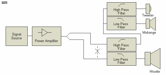
Figure 5 - Bi-Wiring Connections
As can be seen, the low frequency energy is now separated from the mid+high frequency energy in the cabling. The amplifier must still handle the full frequency range, but each section of the crossover has its own cable feed, which may prevent some of the interactions between the crossover sections. Mostly, passive biamping (and/or bi-wiring) is a waste of time and rarely achieves any of the claimed benefits.
The overall effect is often (or so it has been said) a 'vast improvement', largely because of the fundamental imperfections of passive crossover networks. These networks (regardless of their cost or complexity) have a few basic weaknesses which determine their overall performance. Basically, these are:
Many people have said that bi-wiring improved the sound quality, and although I have not used it myself (fully active systems being so far superior), I will reserve judgement until further notice. While there may be some measurable differences, if sensibly sized cables are used the difference is unlikely to be audible unless the loudspeaker's crossover network has serious anomalies.
For more detailed information on the design of passive crossovers, and the many pitfalls involved, read the article Passive Crossover Design. While a mid to high passive crossover can be made reasonably economically and if well designed can sound very good (even excellent), there is often much to be gained by using a fully active system, where each driver has its own amplifier.
Note 1: It must be said that speaker cables in reality contribute little in the way of problems in hi-fi equipment. Much has been made of 'super' cables and the like, but in reality although measurable at audio frequencies, there is no proof that these effects are audible to the majority of listeners. The levels of performance variation caused by the cables are in fractions of a dB, so provided a sufficiently sized cable is used, it matters not whether it cost $2.50 / metre or ten times that amount - except to one's bank account, of course.
Note that the above may not necessarily be the case ... most speaker cables are benign, but some can easily cause a marginal amplifier to oscillate. In particular, be wary of those marketed as having a characteristic impedance of 8 ohms or others offering very low inductance. For more information on this topic, see Cable Impedance. There are solutions for these pointless (IMO) constructions, but it's best to avoid them altogether. Any cable that is capable of making an amplifier unstable cannot offer an improvement, but can easily cause potentially serious problems.
To summarise this section, the complexity of a well designed passive crossover will be such that it will add significantly to the price of the speaker system, while still resolutely presenting the same old problems - power loss, interaction, imperfect impedance matching and rapid phase shifts around the crossover frequency. Variations of loudspeaker driver performance caused by ambient conditions (temperature and humidity for example) will affect all speaker systems (including biamped), but will only cause crossover frequency shifts with a passive network.
| | So now we can add a couple more plusses for biamplifying one's system - complete freedom from any interaction between the loudspeaker driver (and its environment) and the crossover network, and a potentially large cost saving for the now redundant complex passive crossover network. Add to this the benefit that many listeners already claim to experience from bi-wiring - since a biamped system must be naturally be biwired since this is a fundamental part of its operation! |
So far I have only described the low to mid+high frequency crossover, because this is traditionally the most complex and power-hungry part of the network. There are potential gains to be had by tri-amping a system, but they become hard to justify when the added cost and complexity are considered.
The midrange to high frequency crossover still suffers from the same ailments as the low to mid+high, but they tend to be overshadowed by response aberrations created by the edges of the enclosure, grille cloth frames and other discontinuities. For this very reason, many manufacturers now use felt pads around the tweeter to reduce these effects. To some extent, the loudspeakers themselves will generally not be quite as difficult at higher frequencies, because the effects of cabinet resonances, cone mass and other mechanical factors are not as severe as at the low frequency end of the spectrum. This is admittedly a simplification, but the effects are more subtle unless the designer happens to be pushing loudspeakers beyond their limits.
Ferro-fluids are often introduced into the magnetic gap of mid and high frequency drivers, improving magnetic coupling and reducing resonances by way of the additional damping. This technique cannot be used on low frequency drivers, because the excursion of the voice coil is too great and the fluid would simply be flung from the gap as the cone moved.
Since the loudspeakers are actually more controlled at high frequencies, the complexity of the crossover is reduced. Some impedance correction is nearly always needed for the midrange driver (as its impedance will tend to rise with increasing frequency), but this is not especially arduous.
Likewise, padding may well be needed to make the driver sensitivities effectively equal, but especially in a biamped system this should only ever be done to reduce the sensitivity of a tweeter to match the midrange - never the other way around.
If one were to obtain drivers whose frequency response and power handling allowed it, a first-order 6dB/octave crossover network is ideal - good transient response (the best of all filter types, in fact), freedom from phase aberrations, no polarity reversal of drivers - the list goes on.
During this article, I have given great account of the benefits of biamping, but nary a word about any negatives in the equation. There are some, of course, but they have actually been described already ...
An ideal solution would be to incorporate the power amplifiers and electronic crossover within the speaker cabinets themselves. This has been done by many manufacturers (including the author, many years ago), and is becoming quite common for high-end studio monitor speakers, especially some of the new 'near-field' systems.
Even using conventional amplifiers and a separate electronic crossover network, real advantages are to be had. Imagine the best of all worlds - a really good transistor amp for the low end, providing tight and well controlled bass, and a valve (tube) amplifier for the midrange and high frequencies. With its 'soft' overload characteristics and the renowned (by believers at least) openness of a good valve amp, with none of the standard valve amp failings - woolly bass (generally due to the rather poor damping factor of valve amplifiers), and low frequency intermodulation distortion, caused primarily by the output transformer.
In case you might imagine that I actually believe the nonsense that you will read about the alleged 'superiority' of valve amplifiers I hasten to assure the reader that I believe no such thing. Having been taught valve technology at college and after working with valve amplifiers for many, many years, I have no illusions. They can be made to be very good - the very best valve amps were almost as good as a modern transistor amp, but that was when decent valves were available. The quality of valve offerings from the few remaining manufacturers is such that I won't have anything to do with them.
| | Another great benefit has revealed itself. Complete flexibility to choose amplifiers which are at their very best within a defined frequency range. Now the amp which all the reviewers said has "magnificent bass - but is disappointingly lacking at the top end", and the other one which is "glorious at the higher frequencies but suffers from lack of bass extension and tends towards woolliness" at low frequencies can find homes where they really excel! ¹ ¹ Note that claims such as those described are almost always horse-feathers, and no competent amplifier will have any of the 'deficiencies' that reviewers often claim for them. These are subjective terms that have no meaning in a technical sense. |
I could go on (and on) here, but I shall resist the temptation. There is (IMO) no reason to not use biamping wherever possible, from small (i.e. computer) speakers through to top of the line hi-fi. The benefits far outweigh the disadvantages in all cases.
I have seen many claims that loudspeaker manufacturers often go to extraordinary lengths to design the best possible crossover network for their products. I do not doubt that for many high-end systems, this is certainly the case. It must also be considered how much extra this costs, and we can be assured that many systems have a less than ideal network, simply to keep costs reasonable. Several times, I have seen reviews and speaker crossover schematics where expensive speakers use ferrite cored inductors for the low frequencies, and bipolar electrolytics are also common.
I do not consider these to be optimal or appropriate for a high quality system, and nor do many others. The truth is that cost considerations are nearly always made in any system, and much more so when the selling price becomes a consideration.
As I stated at the beginning, if you spend $25,000 - $250,000 (or more) for a pair of speakers, then we are into the 'cost no object' area. Most people cannot afford such luxuries, and as a result they must settle for something they can afford. Only a very few systems will be as good as they can be, and you will pay dearly for it.
Biamping is not a simple tweak, and is not to be taken lightly. Make no mistake though, its application will improve almost any loudspeaker available, with very few exceptions.
There is one area where you may find that changing to a biamped system cases an apparent loss of bass response. This is rare, but in some cases the cabinet design may have been optimised for the woofer, including the resistance of the series inductor in the passive crossover. This is especially true for very well designed ported boxes and transmission line enclosures. The result is that a biamped system is slightly over-damped by comparison, resulting in a loss of bass response.
There are two solutions for this ... either allow the system to 'break in' (which actually means that you get used to the new sound after a while), or increase the output impedance of the power amp. See the ESP articles index for more information on how to go about this. In general, the impedance variation is small, but it is certainly worth doing if you wish to get the best possible response from the system.
Main Index
Articles Index