
|
|
| Elliott Sound Products | Project 09 |
 PCBs (revision C) are available for this project. Click the image for details. (See Also Project 81 for details of the 12dB/octave version).
The Linkwitz-Riley filter featured here has (almost) perfect phase-coherency, with no peaks or dips at the crossover frequency. The design is adaptable to 2-way or 3-way (or even 4-way) operation, and all formulas are provided below (or use the ESP-LR component calculator program). This has been a very popular project since it was published, and that popularity continues to this day. With good opamps, it's performance will generally be better than (supposedly) equivalent DSP (digital signal processor) implementations, because there's no requirement to convert the signal from analogue to digital and back again.
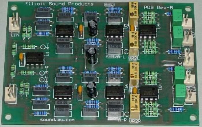
Please note that the PCB version of the P09 crossover is a stereo 2-way design, and has balanced input buffers (which can be connected as unbalanced if preferred), high and low pass filters, level controls and output buffers for each channel. Each output buffer is configured for variable gain to allow your system to be set up correctly. The suggested power supply is the P05 Rev-B, which also has an auxiliary output suitable for operating muting relays (see below for reasons you may want to include muting).
Figure 1A shows the general concept for a full stereo version, with two identical filter sections (but without balanced inputs). With the component values shown, these have a crossover frequency of 310Hz (refer to the article on Bi-Amping to see the reason for my choice of frequency). This unit will provide a completely flat frequency response across the crossover frequency, with the signal from both filters remaining in phase at all times. Note that the frequency shown here is simply an example - it can be anything you like within the audio range.

Note that the PCB version is almost identical, but offers the choice of a balanced or unbalanced input stage. It's not switchable, but the mode is selected before construction, and links or resistors are installed as needed.
The 2-Way unit is separated into 3 sections per channel ...
It is important with both versions that the filters are properly matched, both within the individual filters, and between channels. While small variations between channels will not be audible, if the high and low pass sections are not accurately matched, then phase and amplitude errors will result. In practice, normal component tolerances cause surprisingly small errors, but matching the capacitors is recommended.
Figure 1B shows the way to connect a 3-Way crossover. This unit produces excellent results, with good phase coherency and a flat response across the entire frequency band.

Figure 1B - 3-Way Mono LR Crossover (2 Needed for Stereo)
I know the circuits look complicated, but each is basically repetition of a common circuit block - the filter section. Since the opamps are all used as unity gain buffers, the use of premium devices is not really essential, so the TL072 type would be quite serviceable in this role (however I do recommend that you use something 'better'). Needless to say, if you want to use better devices (even discrete opamps) you can easily do so. Make sure that any device used is stable for unity gain - this is not always the case with some devices, especially when external compensation is used. In this case, use the manufacturer's recommended value of stability cap for unity gain operation.
 |
Power supply connections (and bypass capacitors) have not been shown, but the diagram shows the standard connections for a dual opamp. The IC is viewed from the top. The ±15V power supply described (see Project 05 - Power Supply For Preamps) is suitable for this crossover as well, and will easily power your preamp and a 3-way version of the crossover. For dual opamps, power is connected to Pin 4 (-ve) and Pin 8 (+ve). Most opamps will function just fine with supplies between ±5V and ±15V |
NOTE: Only one channel is shown for the 3-Way - for a stereo setup, two identical filter circuits are required.
As can be seen, the 3-Way unit is separated into 4 sections ...
In 3-Way mode, the bandpass section must have a high pass section whose frequency is exactly equal to that of the main low pass (bass) filter, and a low pass section whose frequency is equal to the main high pass (treble) filter. (No, this isn't confusing, it just looks that way.) See the chart above for clarification if this doesn't seem to make sense.
If it helps, I have included a block diagram that may make things clearer. This is shown below, and has all the sections for a 3-way crossover network. Again, this is mono, so two complete blocks are used for a stereo system.
Frequencies shown are for reference only, and are the same as described above. Naturally, these will need to be changed to suit your application. Note the dotted connection between the input buffer's output and the input to the low-pass filter. If you were to connect the filters like that (rather than as shown), phase shifts through the system will cause the summed output to be different from what you expect. The sections are connected together to give the best outcome - changes will cause unexpected variations, none of which is likely to be good. Opamps always add some phase shift (albeit small), which can make matters worse.
The frequency responses of each section are shown below, note that the crossover frequency is at the -6dB point, and not at the traditional -3dB frequency. This is an important difference between a Butterworth and Linkwitz-Riley filter, and allows the signals to be in phase across the audio band, regardless of which filter section they are being passed by. The electrically (and acoustically) summed output of this filter is flat, there are no peaks or dips (unless you count 0.11dB as a 'dip'), and no phase reversals are produced (unlike 12dB/octave filters).
A simple test with any electronic crossover is to connect a 10k resistor to each output, and join the other ends together. Run a frequency sweep from an audio oscillator into the input, and observe the output level at the output of the resistor summing network. Most traditional (typically Butterworth) crossover networks exhibit a 3dB increase at the xover frequency, and drop back to the reference level about an octave or so each side. This is a less than ideal situation, since in most cases a similar effect will occur from the speaker's summed acoustical output - assuming that the drivers are 'time aligned' so the output of each is in phase (acoustically speaking) at the crossover frequency. If time alignment is not done, and the physical distance difference between speaker voice coils is large (more than 0.1 wavelength of the frequency concerned), then other acoustical differences caused by phase will tend to overshadow any anomaly in the crossover network.
Frequency response is shown from 20Hz to 20kHz, although the bandwidth is much wider (less than 1Hz is easy, and 100kHz or more can be expected with fast opamps. Insertion loss is 0dB, since there is no gain or loss introduced by the filters in their pass-band. The crossover points are defined by the -6dB points of each filter, and are at 310Hz and 3.1kHz (as expected from the above schematics). The summed response is flat, other than a tiny (0.11dB) dip at just below 3kHz. This is caused by phase shift in the high-pass section of the low frequency crossover.
The connections shown must be used as indicated. As noted above, phase anomalies will cause usually minor (but easily measured) response variations if the filters are not cascaded. If you use the ESP boards, the correct wiring is shown in the construction article. There are other connection possibilities, but the one shown has been used by hundreds of constructors and is known to work very well indeed. one of the goals was to ensure that the treble passes through the minimum number of opamps, because there is less feedback at high frequencies, and distortion may be a little bit higher as more opamps are included in the signal path. This is rarely an issue in practice, but it seems to be a worthy goal  .
.
Note that the above comments only apply to the 3-way version, and do not affect the 'standard' 2-way crossover. It has a summed response that is dead flat, regardless of the crossover frequency.
When you use an electronic crossover, you need some way of equalising the levels from each output to match the power amp sensitivity and speaker efficiency. The circuit for a suitable buffer is shown in Figure 3. There is nothing special about it, but it is designed to give a gain of 2 to allow maximum flexibility, and ensures that the impedance of the pots does not cause any high frequency loss with long interconnects. The gain can be changed by varying the resistor values (Rf1 and Rf2). For unity gain, omit Rf2 and use a link for Rf1.
These buffers should use high quality opamps, and provision for them is included on the PCB, including the trimpot (see the photo at the beginning of this article). If you fine that more gain is required (most likely for the low-pass outputs), simply reduce the value of Rf2. If you need around 6dB more gain, use 3.9k resistors (a gain of 4 or 12dB). You're unlikely to need more as this is twice the gain with 10k resistors.
Several people (including me) have found that the crossover unit has a short 'chirp' or 'snap' (depending on the opamp characteristics) as power is removed, and this may be accompanied by some DC swing. If you use the new version of the P05B preamp power supply, the auxiliary output can be used to activate a 6-pole relay (or as many smaller relays as needed) to short all outputs to earth when there is no power. The normally closed contacts simply short the outputs to ground, and when power is applied the short is removed. P05 (Rev-B and above) boards have a power-on delay and a loss of AC detector that will mute the crossover for a few seconds at power-on, and almost immediately when power is turned off.
Because all common opamps have short circuit protection, this will not cause any damage, and current is limited further by the 100 ohm output resistors.
As you can see from the main circuit diagram, a 4th order Linkwitz-Riley would be difficult to make into a variable network, due to the large number of resistors which need to change. Use of multi-ganged potentiometers is discouraged, because of the matching requirements. Sufficiently accurate 8-gang pots are unlikely to be readily available!
If you absolutely insist on performing the calculations yourself, the formulae are shown below. It's quite easy to set this up using a spreadsheet (OpenOffice, LibreOffice, Excel, etc.) or you can use the calculator program I wrote (see below for details).
(1) R = 1 / (2π × 1.414 × f × C)Where R = resistance in Ohms, π = 3.14159, 1.414 is √2, f = frequency in Hertz and C = capacitance in Farads
(2) C = 1 / (2π × 1.414 × f × R)
(3) f = 1 / (2π × 1.414 × R × C)
(1) This assumes that you have selected the capacitance first, which is the most sensible. Caps are available in fewer different values in each decade than resistors. Capacitors generally follow the 'E12' series, which has 12 values per decade, so:
1.0, 1.2, 1.5, 1.8, 2.2, 2.7, 3.3, 3.9, 4.7, 5.6, 6.8, 8.2, 10
These are multiplied by 10, 100 (etc), to obtain all the values from 1nF - 10nF, 10nF - 100nF, and 100nF - 1µF. Values above 1µF and below 1nF are generally not as readily available in all values, and should be avoided for this design, since very large or very small values will create impedances which are too difficult to handle. Very low capacitor values mean high resistor values (noisy), and even small amounts of stray capacitance on PCB tracks or wiring will create errors. Large values of capacitance mean low impedances, which many opamps may not be able to drive without excessive distortion or clipping.
(2) Is the least useful, since the range of capacitor values is less than half that of 1% resistors (especially if you have access to the 'E24' series resistors - 24 values per decade). Really strange values can be assured, which will require parallel combinations of smaller caps - messy and not necessary.
(3) Is useful to check that the components selected will give you the frequency that you first thought of, or something reasonably close after standard component values have been substituted for the theoretical values you will get with the calculation. In general, a variation of less than 1/3 octave will not cause any problems.
The calculator program is far easier and more fun, too. (Of course I like it - I wrote it  !)
!)
Capacitor values need to be accurate - the standard offering is ±10%, which is not really good enough. If you have (or can get access to) a capacitance meter, simply buy more than you need (they are inexpensive), and select the values to be within 2% or better if possible. My experience is that the tolerance of most MKT and MKP caps is actually better than that quoted, but you do need to check! The absolute value is not particularly important, but fairly close matching is needed to ensure flat response across the crossover frequency, and to preserve the stereo image.
The easiest way to get the '2C' value is to use two capacitors in parallel, each of value 'C'. The PCB is designed for this. In addition, the PCB also provides two places for each '2R' value, and they are in series. This means that you can always get the exact '2R' value, without having to resort to E48 or E96 values which still may not provide the exact value needed.
Resistor values also need to be accurate, and 1% metal film resistors are perfectly acceptable. These are generally available in the E24 series (24 values per decade), allowing a much wider choice of values. Both the E12 and E24 series values are available in the Component Calculator (Help-Preferred Values) for reference. In some shops (oh, really?) you might even be able to get resistors in the E48 or E96 range - these offer an almost limitless range of possibilities (48 or 96 values per decade - awesome!), just don't count on it. There's also the E192 series, but these are likely to be harder to find.
I have heard a report (apparently voiced elsewhere) that there is supposedly a problem with phase shift. The short answer is "nonsense", but a slightly more detailed explanation is called for. There may indeed be a small phase difference between the high and low pass sections, and if so it's because of component tolerance (especially capacitors). for example, if two of the caps in the high pass section are 1% high (10nF and 10.1nF caps used), you'll get less than 1° phase shift between the high and low pass sections. This will cause a peak of 0.036dB - hardly worth getting excited about.
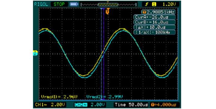
The above shows the measured response of one channel of my prototype P09 board (the one in the photo at the beginning of this page). The cursors indicate that there is a 10us difference between the two signals (yellow is low pass, blue is high pass). At 3kHz, 1 degree corresponds to a time delay of 926ns, so 10µs is a little over 10°. A 10% difference of two of the caps causes a phase shift of ~7°, and causes a 0.36dB peak or dip. Your loudspeaker drivers will have far greater response deviations even under ideal anechoic conditions, and when combined with the room acoustics it's unreasonable to expect normal variations to be less than 1dB (but usually much more).
To minimise phase shift, simply match the capacitors as accurately as possible. If you choose not to bother, it is highly unlikely that you will hear any difference whatsoever. The prototype was built with no attempt to match the caps, other than to ensure they were from the same batch (they were taped together because I buy in bulk). The shift in the crossover frequency is negligible, to the point where it's difficult to measure accurately without sophisticated test equipment. You may be able to measure a small dip (about 0.11dB) just below the mid to high crossover frequency. Since all speakers will be far worse than this, it's not worth getting excited about. The filters can be reconfigured to move it to just above the low to mid crossover frequency, but then you have more opamps in series with the tweeter signal, possibly leading to slightly increased distortion and/or higher noise.
The completed Linkwitz-Riley component calculator is available for you to download. It includes the circuit diagrams for both the high-pass and low-pass sections, and has the following features:
This program (ESP-LR13.EXE) is the actual executable file. This is version 1.3 of the program, and is 88kB, so it is not overly large. There is no setup program, so you simply have to decide where to put it, and create your own shortcut. Feel free to distribute the program to friends, since I have released it as freeware - just don't change the program in any way is all I ask.
The program requires the Microsoft VB6 run-time library, which can be obtained from Microsoft's web site if it is not installed on your machine. Note that the program is 32-bit, so it won't run on pre Win98 operating systems. The following is a guide as to where the DLL (dynamic link library) file should be installed ...
Operating System VB6 Support File Location Windows95 Not supported Windows98 c:\windows\system WindowsNT c:\winnt\system32 XP c:\windows\system32 Vista Should be pre-installed Windows7 See below Windows10/11 Normally pre-installed
The VB6 Runtime Library contains the following DLLs:
Asycfilt.dll
COMCAT.DLL
msvbvm60.dll
OLEAUT32.DLL
OLEPRO32.DLL
STDOLE2.TLB
In all cases, the above assumes that the C: drive is the installation drive. This will usually be the case, but some installations may differ. For Windows7 users, Microsoft suggests elsewhere that the VB6 run-time library will work, but it's not supported for 64 bit versions. I use it on a 64-bit machine though, and found no issues (programs work normally).
Note: Although all care has been taken to ensure the file is virus free, ESP cannot absolutely guarantee that this is the case - I don't appear to have any viruses on my machine, but one cannot be too careful. As with all executable downloads, use your own virus scanner to check it before execution.
 Main Index
Projects Index
Main Index
Projects Index