
|
|
| Elliott Sound Products | Baffle Step Compensation |
 Main Index
Articles Index
Main Index
Articles Index
The so called 'baffle step' is an increase in output from a loudspeaker as the size of the baffle becomes significant in terms of the wavelength of sound for a range of frequencies. At low frequencies, where the baffle (the panel the loudspeaker is mounted on) is small compared to the wavelength, the speaker is assumed to be operating with a spherical radiation pattern. While this may be the case should the speaker be situated up a tree in the middle of a field, it hardly qualifies as true when the same loudspeaker is installed in your listening room. There may of course be something about you that I don't know (for example that your speakers really are up in trees), but for the majority this will not be the case.
As frequency increases, the size of the baffle becomes significant, and the spherical radiation pattern no longer applies. This is also partly to do with the loudspeaker drivers themselves - as frequency increases, typical cone drivers become more and more directional anyway - this occurs as the dimensions of the cone become significant with respect to wavelength.
While many people will claim that baffle-step EQ is essential, that's not always the case. With speakers that are against (or close to) a wall, there will be other reinforcements and cancellations that often have far greater effect than any baffle-step. If the system is active (i.e. electronic crossover) and has a bass to midrange crossover at the same frequency as the baffle-step, it's just a matter of adjusting the bass level a tad higher. For example, if the baffle is 300mm wide and the crossover frequency is around 380Hz, that is a perfect match.
It has been shown by Olson et. al. that the optimum enclosure for a loudspeaker driver is a sphere - that is to say that there is no 'baffle' as such, but that the driver is installed in a spherical enclosure. While this is all very well in theory, spheres are hard to build, and even harder to include in a typical lounge room unobtrusively.

Figure 1 - Response Behaviour - 300 mm Sphere (After Olson)
The increase in output can be seen as the dimensions of the sphere approach the wavelength of the reproduced frequency. Once the wavelength is smaller than the diameter of the sphere, the response flattens out again, having risen by 6dB from the low frequency level. The radiating efficiency of the driver starts to increase earlier than one might imagine - there is a 1dB increase in SPL at the frequency where the baffle is about 0.2 of a wavelength, and the baffle step effect has no influence when the baffle width is greater than 3 wavelengths. At this point, the driver is effectively radiating into a hemisphere.
The absolute worst enclosure is a circular tube (cylinder), with the driver mounted in the exact centre of an end-cap. The response ripples caused by this are extreme, but with most systems this is not an issue, since this would be a very unusual shape for an enclosure. The response for a cylinder with the driver mounted at the end shows fluctuations in level that are quite unacceptable, and it is not a shape I would recommend to anyone. A cube is little better, and again the effect is made very much worse if the driver is mounted in the centre. Because these shapes are (or should be) avoided altogether, I have not included any response graphs. For this reason, it's best to try to ensure that midrange and tweeter drivers (in particular) are installed so they are a different distance from each edge of the baffle.

Figure 2 - Response Behaviour - 300mm Wide Rectangular Box (After Olson)
The overall behaviour is greatly improved with any mounting method if you ensure that the centre of the driver is a different distance from each edge of the box. These distances should be 'non-harmonic', which is to say that they should be different, but in such a way that no one distance is an even multiple of any other. Options include a ratio of 1.414:1 (√2) or the 'golden ratio' (1.618:1). For more information on this, see Loudspeaker Enclosure Design Guidelines.
When the distances from the driver centre to three sides are equal, the response will be much like that shown in Figure 2. This is better than a cube or cylinder, but much greater improvements can be made, just by changing the position of the driver. In addition, rounded edges will cause less refraction than square or raised edges, further improving the overall response, and particularly at the higher frequencies.
The baffle step is easily compensated for where the speakers are mounted in trees or are in other (more sensible) outdoor environments, but becomes much more difficult as a normal listening room is introduced. Adjacent walls, cabinets and other furnishings will all have an effect, and the outcome is unpredictable at best.
It has been determined that the baffle step may only be a couple of decibels in some circumstances, and sometimes less. In a normal room, it is unlikely that the step will be greater than 3dB, unless the speakers are a considerable distance from the walls.
To this end, I have determined a simple passive network that allows you to adjust the level with a pot, until the response is optimum. The frequency is fixed, and is easily determined based on the width of the baffle. The equaliser circuit should be placed between the preamp and power amp - it is not suitable for use in the speaker lines. Although circuits exist for use in the speaker lines, I would not recommend them in any situation, since power losses are very high, and they cannot be adjusted easily to suit your listening environment.
Based on an excellent formula developed by John Murphy (True Audio), we can calculate the frequency easily for the box ...
f3 = 115 / WB (where WB is the baffle width in meters) f3 = 380 / WB (where WB is the baffle width in feet)
Needless to say, I will use metres, and as shown in the graphs above, I will use a baffle 300 mm wide. The frequency is therefore ...
f3 = 115 / 0.3 = 383 Hz
A circuit is needed that will provide a typical 3dB decrease in level at the calculated frequency, and the (very simple) schematic is shown in Figure 3.
The value of C1 is determined by the following (1/2 of the pot value is added to the resistor value, since both are in series, and a typical situation will have a pot setting of around halfway - there will always be some error, but it will normally be quite small in practice) ...
C1 = 1 / ( 2π × ( R1 + VR1 / 2 ) × f ) C1 = 1 / ( 2π × 15k × 383 ) = 27nF
Since the formula will regularly give values that are not obtainable, we may use the closest available value with little error. Certainly the error will be very much smaller than that created by the room acoustics and other influences. The sample circuit is shown in Figure 3, and as shown is valid for a box with a 300mm wide baffle. The only change that you will need is to the value of C1 according to the above formula.
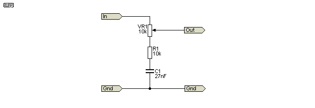
Figure 3 - The Baffle Step Correction Circuit
It is essential that the compensation circuit be driven from a low impedance source, and the load impedance should be reasonably high. There will be little error with loading above 20k, but basically the higher the impedance, the better. Opamp buffers at the input and output may be used if you cannot ensure that the source impedance is 100 ohms or less, and that the load impedance of the following stage is ideally greater than 100k. My recommendation would be to use a buffer stage at the output with an input impedance of at least 100k. Note that the pot must be linear!
An alternate is to use a 1k pot and 1k resistor, along with a 270nF capacitor. This is more tolerant of 'typical' input impedances for power amps, but the preamp must be able to drive the 2kΩ load. Most will, but valve (vacuum tube) preamps will have problems. The formula is the same as shown. You can use any pot value between 1k and 10k, with a resistor the same value as the pot. This allows more flexibility and may allow you to use a pot you have available.
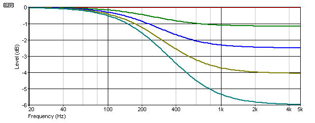
Figure 4 - Typical Frequency Response at 25% Increments
As shown in Figure 4, the pot may be moved from a flat response right through to full 6dB compensation. The graph shows 25% increments of the pot. When the pot wiper is at the top of its travel (based on the schematic), the circuit is inactive, and maximum compensation occurs at the opposite end of the pot's travel. Nearly all normal listening room environments will use a setting somewhere in between.
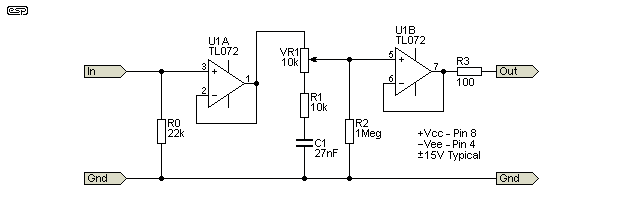
Figure 5 - Active Baffle Step Correction Circuit
The circuit above isn't 'active' in the normal sense, as it simply includes an input and output buffer. Although I've shown a TL072 opamp, many people are likely to want something 'better', although it's highly unlikely that there will be any audible difference. You could use an NE5532, OPA2134 or your preferred type. Since they are unity gain buffers and have 100% negative feedback, it's doubtful that the performance of any opamp will be found wanting. The second stage has a 1MΩ input resistor, which is only present to prevent very (very) loud noises if the pot develops a high-impedance fault. No-one wants the output of a preamp to be high-level DC ! The frequency response is unchanged from that shown in Figure 4.
The arrangement shown works well, but in some cases it may be felt that the impedance is higher (or lower) than you may prefer. Provided you use an opamp to buffer the input (or it's fed from a low impedance source), you can reduce the resistor and pot values to suit what you have available or think is preferable. A reduced impedance will be helpful if the input impedance of the following stage is less than 100k (either a power amplifier or electronic crossover). Obviously, you can use a buffer stage after the baffle-step EQ circuit (as shown in Figure 5), which ensures that there is next to no loading at all.
If you use an opamp such as the OPA2134 as the input and output buffer, the total impedance of the network can be as low as 600 ohms, and using a 1k pot, 1k resistor and a 270nF capacitor gives the exact same response as the network shown above, but it has a far lower output impedance. The values can be changed to suit what you have available, but I don't recommend that you use pots/ resistors greater than 10k or less than 1k (the latter because they are too hard for most opamps to drive).
Note that John Murphy's article was the inspiration for this offering, and there are many other references quoted in his original article (See http://trueaudio.com/st_diff1.htm)
Main Index
Articles Index