
|
|
| Elliott Sound Products | Effects Of Source Impedance on Loudspeakers |
 Main Index
Articles Index
Main Index
Articles Index
This is not the final word on this topic, and I am sure that others with more (and better) equipment than I have could do much more. An hour or so of testing is hardly a fully scientific study, but the results agree with expectations for voltage and current drive - what came as a surprise was just how nasty negative impedance really can be.
The general idea of current drive (or at least a reasonable value of positive impedance) has been with us for a long time. Most valve (tube) amps operate with a non-zero output impedance, and it typically varies from as much as double the nominal speaker impedance, to perhaps half of the speaker's impedance. Some of the very high-end valve power amps towards the end of their reign managed to get output impedance that is comparable to that of many transistor amps. I started playing with current drive for hi-fi sometime around 1975, but I'd been using it for some time before that.
There are now quite a few people expounding the great benefits of current drive, including suggestions that conventional voltage drive is so incredibly flawed that it cannot possibly work properly. This is obviously nonsense, and it it were true, no loudspeakers from any manufacturer could reproduce a hi-fi performance. The fact is that virtually all modern loudspeaker drivers are designed, manufactured and specified for operation from a voltage amplifier - one having a near zero output impedance.
Does this mean that current drive can (or should) not be used? Of course not - current drive can do some useful things for loudspeakers, but none of these things are magic, and none will reduce the loudspeaker's distortion by any useful amount or create sound that is otherwise unattainable.
This article was originally prompted by a reader who did some simulations of a loudspeaker having no voice coil resistance. Of course, this is not possible, but driving with negative impedance can theoretically accomplish the same thing.
Negative impedance has been around for quite some time (probably about 50 years, maybe more), but I suspect that I have one of the few amplifiers around that can be preset to any impedance between -16 Ohms and +32 ohms. To this end, it was reasonably easy to test, and I used 42Hz as the test frequency - being representative of a typical bass signal (open 'E' on a bass guitar). Just to make matters as bad as they could be, this is also very close to the resonant frequency of the test loudspeaker and enclosure.
I used a sound level meter at close range (100mm) connected to my oscilloscope to see the actual loudspeaker waveform. The speaker is a 4 Ohm 300mm Cerwin Vega subwoofer, in a 28 litre sealed box. This box has been used many times as a test system for the Electronically Assisted Subwoofer (see EAS project), described on these pages.
During these tests I deliberately made no attempt to use zero crossing switching, since this was difficult for a quick test, and would obscure some of the effects that are only triggered by a transient. The lower trace is the output from the signal generator, and switching could - and did - take place whenever I switched the signal on and off.
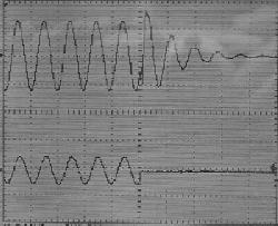
The upper trace of each oscilloscope screen photo is the signal taken directly from my sound level meter, and the lower trace is the input signal. I made no real attempt to maintain any specific level, since it was immediately apparent that this made little difference.
The waveforms displayed are exactly as measured, and the phase and timings were not tampered with in any way. The input signal was not bandwidth limited, nor was the amplifier output - the test results are therefore 'worst case'.
Transients are generated at the moment of switching - it is predominantly these that are of interest - a photo of an oscilloscope trace of a 42Hz waveform is fundamentally boring, whatever the source. The oscilloscope traces shown were captured with my digital camera - less than ideal, but it works (other than the ghostly image of the camera reflected in the front of the display). Note that these tests were carried out before I got a digital scope with the ability to capture the waveform as an image.
Voltage drive is the most common way to drive loudspeakers. In theory, a 'perfect' voltage amplifier has zero ohms output impedance, but this is never achieved in practice. Output impedances of 0.1 ohm or less are not uncommon at low frequencies, representing a 'damping factor' of 80 or more.
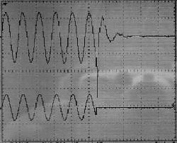
Voltage Drive - Z = <0.5 Ohms
One might say that this is text book performance. There is evidence of the switching transient, but overall this combination is well behaved. This is the most common connection for loudspeakers, and seems to be about as good as it gets. Overhang (ringing after the signal has gone) is almost non-existent.
With a pure current drive signal, the input determines the current that flows through a loudspeaker (or other) load. This is rarely used in practice, as it is unsuitable for driving speakers. Using a defined impedance means that the amplifier's output is dependent on the load impedance at any given frequency, but in a way that is predictable. This can be used to advantage, but is most commonly (and IMO incorrectly) frowned upon. Generally, I would suggest that the amplifier's output impedance should be no greater than the speaker impedance (and preferably less). This arrangement is particularly suited to guitar amps, and is greatly preferred by most guitarists. Many bass players also prefer a modified current drive signal. All currently available valve guitar and bass amps will be very similar to this test.
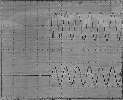
Current Drive - Z = +3 Ohms
The switching transient is still in evidence, as is to be expected - the big spike is a result of the switching point, and is not unique to current drive. The attack is almost perfect, but a slight ringing is apparent when signal is removed. Although this is quite visible, it is inaudible (at least in my workshop), and since bass signals don't normally stop partway through a cycle, it is unlikely to be audible in a typical room, the response of which will be far worse than the speaker.
This is the same as the previous definition, but in this example, the output impedance was increased to 32 ohms - this is 8 times the quoted impedance of the speaker I used. We are getting close to true current drive, since a change in the speaker impedance (with frequency) has little effect on the voicecoil current.

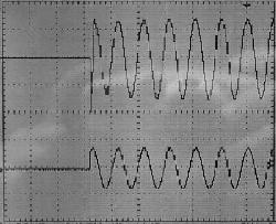
Current Drive - Z = +32 Ohms
This is an extreme impedance, and would rarely be used in practice - never for anything that aspired to high fidelity. There is a slow attack, with the signal building up to the steady state level. Considerable ringing is apparent when the signal is removed. This is both visible and (in my workshop, only just) audible. This is not a good combination for hi-fi, but may be quite acceptable for a guitar or bass amp (for example), as the colouration simply adds timbre to the sound of the instrument. The switching transient is almost non-existent, as the energy is converted into underdamped cone movement instead.
This is 'slow' bass, with a woolliness that may be attributed to some valve amplifiers - especially those with no (or very little) feedback. There are many people who like the sound like this, and this is perfectly OK. Each to his own, and all that. In general, the impedance is too high in my opinion, although it is not especially uncommon for guitar amplifiers.
Negative impedance does exactly what it implies - when the load is increased (with a lower impedance), the signal applied to the load increases (i.e. the exact opposite of what normally happens). This results in an intrinsically unstable system, and great care must be taken to prevent the creation of an oscillator.
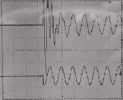

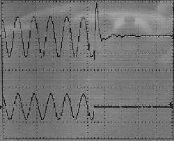
Negative Impedance Drive - Z = -3 Ohms
The performance of this combination is completely unacceptable in every sense of the term. This combination could never be used in practice, for any reason. There is a vicious attack, with the signal doing something at a frequency completely unrelated to the input signal - unrelated in any way that I can determine, at least.
Considerable ringing is apparent (again at an unrelated frequency) when the signal is removed. This is highly visible and audible, and the sound of the attack and decay is grossly inferior to any other combination. The others (using positive impedance) have some character, but it is related to the signal, and makes some sort of musical sense.
To add insult to injury, the amp decided to become an oscillator (at about 15Hz) on a few occasions, this being one of the risks of negative impedance. It subsided, but was a little disconcerting. I doubt that this is high on the 'desirable' list for most audiophiles. Although negative impedance systems have been used for obtaining bass extension, there is a fine line between proper operation and instability. Frequency shaping filters are generally used to limit the negative impedance to a specific frequency range to minimise instability and/or other undesirable effects.
Reducing the negative impedance to -1.5 Ohms stopped the oscillation entirely, but the effect on the attack and decay performance was merely a minor reduction of the many artifacts created, and was still quite unacceptable. Filters and other treatment may give results that are usable, but negative impedance is generally something to be avoided.
As a side note, it's worth pointing out that some amplifiers may show very slight negative impedance during testing. This is almost always because of a poor choice of internal cable routing, but where it happens the actual amount of negative impedance is tiny (a small fraction of an ohm) and will not normally cause any audible problems. However, it may account for some of the differences heard between amplifiers that should have no audible differences. This is in no way a certainty though - I suspect that most people will hear no difference at all in a double-blind test.
A simulation can't be the same as the acoustic output, but it's still useful to see how the voltage across a loudspeaker changes when the source impedance is modified. The simulated speaker is shown first, so you can see the equivalent circuit of the speaker that was used. Resonance is at 46Hz, and the signal was provided at a frequency of 44Hz. Unlike the photos of oscilloscope screens shown above, the signal was gated to allow 5 cycles on, and 5 cycles off, with the switching done at close to the zero crossing. Five cycles is sufficient to ensure steady state conditions are achieved before the signal is turned off.
Simulated Speaker
This speaker equivalent circuit has been used in several other ESP articles. It is a reasonable representation of a loudspeaker, but of course it can't show the acoustic output. Resonance is 46Hz, reaching a maximum impedance of 50 ohms, and nominal impedance is 8 ohms. It includes the cone mass (18mH inductance), suspension 'spring' (660µF) and semi-inductance of the voice coil (1mH || 12 ohms). Voicecoil DC resistance is 6.8 ohms.
Zero Ohm Source
With a zero ohm source, the signal across the speaker exactly matches the amplifier output. This same signal was used for the other simulations. You can see that the signal is switched at very close to the zero-crossing point. The simulations were allowed to run for 200ms before the output was plotted to ensure that steady state conditions were established.

+8 Ohm Source
With partial current drive (8 ohms output impedance) the (relatively) slow voltage build-up when signal is applied is clear, as is the ringing when the signal stops. This is normal when a loudspeaker is driven from a high impedance source, but these effects are not normally visible. They show up clearly here because the signal was set for a frequency just below speaker resonance. This effect is audible, but it's not objectionable. Adding heavy acoustic damping to the enclosure makes much of the audible artifacts go away, but there will always be an apparent 'improvement' to bass response. The result is sometimes described as 'musical', in that the result sounds 'nice' (at least at first).

-2.7 Ohm Source
The application of -2.7 ohms negative impedance pretty much reverses the effects seen when a 'normal' high output impedance is used. The first half-cycle is now greater than the steady state level, and the polarity of the ringing (after the signal stops) is reversed. That's the point where things go pear-shaped, and the effect is audible. Damping the enclosure doesn't help a great deal, and the sound is un-natural and definitely not musical.
If the effects of random switching are taken away, these simulations are much closer to the measured results than I expected. Naturally, the effects are very different with music or other programme material (e.g. speech), because most natural sounds cannot (and do not) start and end abruptly. The results clearly demonstrate that simulations can easily reproduce reality if done carefully.
As I mentioned in one or more articles on these pages, I have never found a cone speaker that 'likes' negative impedance. Horn compression drivers seem quite happy and this is a test that I will have to run at some stage to measure the results, and how it affects the sound (other than an apparent improvement in bandwidth).
The net result of these tests indicate what has long been known - that voltage drive remains the best choice for most loudspeakers, regardless of some desirable characteristics of defined current drive. With additional internal damping, moderate current drive can modify the Qts of the loudspeaker driver, and allow an enclosure design that is (typically) larger than optimal for flattest amplitude (Butterworth) response.
It should be noted that the simulation and measured results compare quite well, and somewhat better than I expected. We don't see the wild excursions with negative impedance in the simulation, but remember that the simulations all used (close to) zero-voltage switching. It's very difficult to simulate the random make/break action of a mechanical switch in any simulation, but the trends are still clear. This is despite that fact that only the voltage across the speaker was monitored, because there is no way for the simulator to even pretend to monitor the acoustic output.
There was recently an article in Electronics World, where it was claimed that current drive helps to compensate for the resonant peak and voice coil inductance in a driver. While this is undoubtedly true (I've been doing it for many, many years), the designer must be very careful to ensure that the enclosure is particularly well damped, to avoid 'overhang' when the signal is removed. This will typically manifest itself as poorly defined bass, particularly on transients, since the speaker must rely primarily on its own devices for damping.
Overall, this exercise has simply proven that which has already been proven by so many before me ...
For further reading on the subject of modifying amplifier impedance, see the Impedance article, and Project 56 (Variable Impedance) shows you how to accomplish this.
Main Index
Articles Index