

|
| Elliott Sound Products | Project 56 |
Is this a project or an article? Since you may have arrived here from either index, you might be a little confused. This is fine, as it has elements of both, but lacks the in-depth analysis of other articles, and also lacks the application of a final design that is common to my projects. This is for the experimenter. No further work will be done to refine formulae or produce 'magic' spreadsheets to allow you to determine the impedance that is best for a speaker/ enclosure combination or anything else. Readers' contributions are of course welcome, and I would be interested to hear about any massive improvements that were made to systems using these techniques. (Or minor improvements, for that matter.)
The idea of being able to vary the output impedance of a power amplifier has been around for a long time. I have used these techniques since the early 1970s in various designs, and much as I would like to be able to claim otherwise, I was by no means the first. I don't know of anyone else who's gone to the trouble of building a 3-way amplifier with variable output impedance though, and the continuously variable version shown in Figure 7 is (as far as I'm aware) unique.
The technique has been (and still is) used to drive spring reverb units, and various other transducers where current drive is either preferable or essential, and where voltage drive is inappropriate. For many years (even before transistor amps), voltage drive has been what we all strive for with power amplifiers - a perfect (ideal) voltage amplifier has zero ohms output impedance, and the amplitude does not change as the load varies. Loudspeakers are very non-linear loads, and the impedance will change at different frequencies for all sorts of reasons. Voltage drive has an advantage, because it is easy to achieve (well, at least down to well below 0.5 ohm) and, most importantly, it is easy to achieve consistency !
Voltage drive maintains a constant voltage across the load, while a current drive circuit will maintain the same current through the load - in both cases regardless of impedance. The voltage and/or current must (of course) be within the range that the amplifier can provide, limited by supply voltage and non-destructive output current (usually determined by the transistor's SOA - safe operating area). The voltage or current is determined by the magnitude of the input signal. A voltage amp is a voltage controlled voltage amplifier, and a current amp is a voltage controlled current amplifier (aka transconductance amplifier). In reality neither approach is ideal ...
The converse of the two statements above is also true of course. Most loudspeaker drivers and systems are optimised for voltage drive, however in some cases 'optimised' is term applied loosely, since they are just assembled (perhaps to a set of plans, perhaps not), and the builder hopes for the best. A tweak here, an attenuator there, and a Zobel network somewhere else rounds off the process and yet another 'world's best' loudspeaker system is born.
Not so much a real project as a field day for experimenters, this article describes the methods you can use to tailor an amplifier to a specific driver. Much is empirical (i.e. design by experiment, trial and error), and although formulae are possible, the load presented by a typical loudspeaker is very complex and leaves big holes in the final result if the maths are allowed to take over. Having said that, good results can be obtained by either method (theoretical or practical).
One place where this technique has been used is in a contributed article - see Compliance Scaling and Other Techniques (Fitting just about any driver to just about any alignment), so to learn more, read on ...
Figure 1 shows two amplifiers (shown as opamps), with (A) being conventional voltage drive, and (B) is current drive. The output impedances are in the order of zero ohms and infinite ohms in each case (this is a theoretical discussion at the moment!). The gain will appear to be exactly the same for each into an 8 ohm resistive load, but will change based on load for the current amp. We shall see that this is not really the case - some power is lost in the series feedback resistor. The voltage amp has the same gain regardless of load.
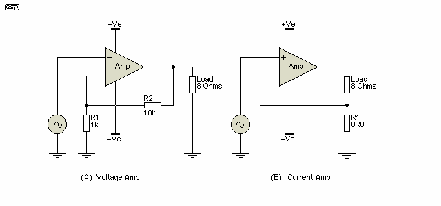
Figure 1 - Voltage and Current Amplifiers
The feedback is applied differently to achieve the desired result, as can be seen, although the difference is not at all subtle at first glance, as you look more closely you will see that it really is a simple rearrangement of feedback resistances. With the 8 ohm load, both amps have a gain of 11, but the series feedback in (B) actually means that the gain to the load is 10. With 1V AC signal applied, the voltage amp will develop 15.125W (11V at 8 ohms) into the load. The current amp will develop 12.5W (10V at 8 ohms) into the load, with 1.25W dissipated as heat in R1. This will remain constant for all load impedances with a steady state signal.
Where things get interesting is when the load impedance changes. Should the load increase to 16 ohms (such as near resonance), the voltage amp will produce the same voltage, so power is halved. The current amp will provide the same current, so power into the load is doubled to 25W, with the same 1.25W lost in the series feedback resistor. This of course assumes that the power supply voltage is high enough to allow the amp to do this without clipping.
Likewise, with a dip in impedance to 4 ohms, the voltage amp will provide double the power (30.25W - now assuming the amp can provide the necessary current), but the current amp will only produce 6.25W under the same conditions.
Which of these approaches is correct? For resistive loads it doesn't matter - both will perform identically except for the slightly lower gain (and small power loss) of the current amp due to the current sense resistor (this is easily compensated for). With loudspeaker loads, neither is ideal. Power to the load will vary widely depending on the impedance, which in turn depends upon frequency. The voltage amp will create a dip in response at each frequency where the impedance rises (and a rise wherever there is a lower impedance), and the current amp will do exactly the opposite.
It must be considered that almost without exception, loudspeaker drivers and complete systems are designed based on the assumption that the amplifier has a low (less than 0.5 ohm) output impedance. If driven using current drive (full or partial), the result always sounds different, and because of extra bass (and usually treble), people tend to equate 'different' with 'better'. They are not equivalent, and the result is almost invariably worse, with uneven frequency response and poor low frequency damping. The only exception is if the speaker enclosure and amplifier are designed 'as-one', with the output impedance of the amplifier matched to suit the driver's performance.

It is worth pointing out that the current drive system shown above should never be used in practice. The low frequency open loop gain is effectively infinite, and it will be prone to pick up radio and other interference. While the technique is still perfectly valid, it can only work properly with instrumentation systems where everything is enclosed in the one case and the load is controlled. For audio, use the following method ...
By applying a mixture of both forms of feedback, it is possible to define the output impedance at any value between the two extremes. To emulate a valve amp for example, an output impedance of about 4 to 6 ohms is needed, assuming an 8 ohm load (this is the assumed nominal load impedance for all examples cited). Note that some valve amps may have a much higher output impedance. Without any doubt whatsoever, mixed mode feedback is the preferred option if you wish to experiment.
Figure 2 shows the arrangement used, and with the values shown the output impedance is a bit under 4 ohms. We could simply use a 4 ohm resistor in the amp's output, but this will waste as much as half of the amplifier's output power, which will be dissipated in the resistor instead of the load. The same power output is available from a current amp as a voltage amp (give or take a fraction of a dB to account for the series feedback resistor).
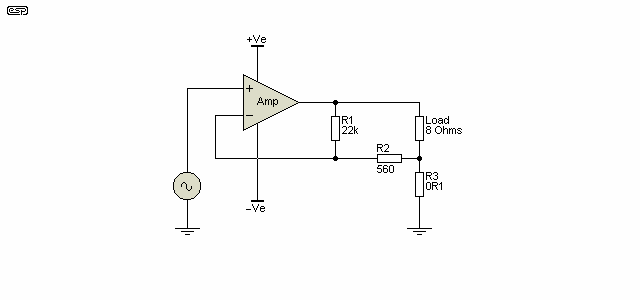
Figure 2 - A Four Ohm Output Impedance Amplifier
As can be seen, there is minimal additional complexity to achieve this result, and in my experience the final exact impedance is not overly critical, given the 'real world' variations of a typical loudspeaker driver.
The no-load voltage is 40.27V with an input of 1V, and this drops to 26.8 at 8 ohms, and 20.07V with a 4 ohm load. These voltages are measured across the load, ignoring the voltage drop of the series feedback resistor. Note that a resistive load is assumed, because a speaker has an impedance that varies with frequency.
It's immediately obvious that if a 4 ohm load reduces the voltage to exactly half, then the output impedance must be 4 ohms. With an 8 ohm load, we can calculate the exact output impedance from ...
| I L = VL / RL | (where I L = load current, VL = loaded Voltage and RL = load resistance) | |
| Z OUT = (VU - VL) / I L | (where Z OUT = output impedance, VU = unloaded voltage, VL = loaded voltage) | |
| I L = 26.8V / 8Ω = 3.35A | ||
| Z OUT = (40.33 - 26.8) / 3.35A | = 13.53V / 3.35A = 4.04Ω |
Note that I have deliberately not developed a single formula to calculate impedance, because no-one will remember it. By showing the basic calculations (using only Ohm's law), it becomes easier to understand the process and remember the method used. An approximate formula to calculate Z OUT was previously shown, but it's not accurate enough to use and has been withdrawn. There will always be compromises when designing an amplifier for a particular output impedance. It's unrealistic to expect a simple formula based on loaded and unloaded gain (both of which vary with impedance). It's far easier to simply adjust the value of R2 (and/ or R3) to get the impedance you want, and make up the gain or attenuation externally.
So we have created an amp with an output impedance of 4 ohms, with very little loss (just over 0.5W is lost in the 0.1Ω series feedback resistor with 20W output into 8 ohms). To see if this is useful, we will now have a look at what happens when the load impedance doubles or halves.
With a 16 ohm load, the power into the load falls to 14.6W, or about 1.37 dB. Contrast this with the conventional low impedance amp whose power will fall by 3dB (i.e. half).
When the load impedance is reduced to 4 ohms, the output power is now 23.5W (an increase of 0.7dB), while a conventional amp would be producing 40W - an increase of 3dB.
There is no magical impedance that will give the same power into any load from double to half the nominal, but about 4 ohms for a nominal 8 ohm system comes close. I am not about to test all possibilities, but having experimented with the concept for many years I am quite convinced that there are practical benefits to the use of modified current drive, where the impedance is defined. The exact impedance will depend to a very large degree on just what you are trying to achieve.

Note: It is imperative that you ensure that the amplifier remains stable when loaded. In some cases, the Miller capacitor (aka 'dominant pole') may need to be increased if the loaded gain is less than the design value. For example, most ESP designs are set for a gain of 23 (27dB), and if the combination of voltage and current feedback reduces this significantly, the amplifier may become unstable. This is not predictable, and needs to be verified using a dummy load with the same impedance as the lowest impedance presented by the loudspeaker.
It has been suggested that loudspeaker intermodulation distortion is dramatically reduced by using a high impedance source [ 2 ]. One site I looked at some time ago was Russian, and a reader sent me a translation. I have experimented with this idea to some extent, but have been unable to prove that this is the case - at least with the drivers I tried it with.
This does not mean that the claim is false, but I am unable to think of any valid reason that could account for such driver behaviour. It is interesting anyway, and some of you might like to carry out a few experiments of your own. I would be most interested to hear about your results should you decide to test this theory. It's worth remembering that with no exceptions I can think of, loudspeaker drivers are designed for (and tested with) as close to a zero ohm source impedance as possible. All commercial speaker systems are designed to be fed with a normal low impedance power amplifier, because that's considered the 'ideal' case and virtually all commercial hi-fi and sound reinforcement amps are designed for (very) low output impedance.
By adjusting the impedance of an amplifier, the total Q (Qts) of a loudspeaker can also be altered, so driver behaviour in a given sized box can be changed. This can be used to adapt an otherwise unsuitable loudspeaker to a speaker enclosure, but it does have limitations in terms of the overall variation that can be achieved.
More variation can be achieved by virtue of the fact that it is now possible to either retain or increase the power delivered to a loudspeaker at (or near) resonance, so that the ultimate -3dB frequency may be lowered from that theoretically claimed for a loudspeaker/ enclosure combination. Care is needed, since too much additional power will make the speaker boomy, and usually additional internal damping material is needed to compensate for the minimal damping factor provided by the amplifier. With the amplifier output impedance set at 4 ohms, damping factor into an 8 ohm load is 2 - a far cry from the figures of several hundred typically quoted. These (of course) fail to take into consideration the resistance of the speaker leads, and loudspeakers themselves are usually compromised by the crossover network, so the damping factor figure is not always as useful (nor as high) as it might seem.
The results of using modified impedance can be very satisfying, allowing a useful extension of the bottom end. My own speakers are driven from a 2 ohm amplifier impedance, and there is no 'boominess' or other unpleasantness, but a worthwhile improvement in bass response is quite noticeable.
Again, this has been about for many years, but I have only found one driver type that seems to obtain any improvement from its use - horn loaded compression drivers. All cone speakers (including horn loaded) sound worse with negative impedance, but you might have some weird driver that can benefit from a negative impedance amp. I once heard it said that "you can't control a compression driver from an ohm away", meaning that just one ohm (but often more) in series with a compression driver will mess up its performance. I've not seen anything to suggest that this is not true.
As the name suggests, when a negative impedance amp is loaded, the output voltage rises. The greater the load, the more output is applied. This is very risky, and negative impedance amplifiers are intrinsically unstable, and can easily oscillate when connected to a reactive load such as a loudspeaker. Indeed, negative impedance oscillators have been with us for many years in RF (and other) work, and there are quite a few electronic components that exhibit negative impedance. So, not new, but interesting.
Figure 3 shows how the circuit is rearranged to accomplish this most bizarre of ideas. By simply connecting the non-inverting input of the amp to the junction of load and series feedback resistor, the voltage developed across the resistor now increases the gain by adding to the input signal voltage. The amp is now inverting (previous examples were non-inverting)
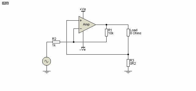
Figure 3 - Basic Negative Impedance Amplifier
This circuit with the values as shown will provide an open circuit load with 10V (as will a conventional inverting amplifier), but when the load is applied the voltage increases as the load resistance is reduced. With the values shown, the no-load voltage of 10V will increase to 13.3V with an 8 ohm load, rising to 20V with a 4 ohm load. A quick calculation using the formulae above will show that the output impedance is -2 ohms.
The negative impedance amp is by its very nature unstable - the output voltage will continue to rise as the load is reduced, until at some point positive feedback exceeds negative feedback and the circuit will oscillate. Another undesirable side-effect is that distortion is increased, because negative feedback (which reduces distortion) is being counteracted by positive feedback. Again, this is a non-linear function, and the results can be unpredictable at best. For example, if the actual load impedance falls to 2 ohms at any frequency, the amplifier gain is effectively infinite (it becomes an oscillator - at full power!)
Reactive loudspeaker loads can cause a negative impedance amp to oscillate, either at the box resonance frequency (where impedance falls to a minimum), or at some other frequency determined by crossover components. Such oscillation can damage speakers (and ears!), so care is needed to ensure that this cannot happen. Low values of negative impedance (not less than -4 ohms) are strongly recommended.
I have found that only small amounts of negative impedance are useful in practice. For example, one could use negative impedance to remove the resistance of the speaker cable and crossover components, although the results will not be as good as expected, and probably far worse. Even with a negative impedance of about 1 ohm, most speakers will have audible signs of 'displeasure', and amplifier distortion will be increased - usually by an amount that is disproportionate to the feedback factor.
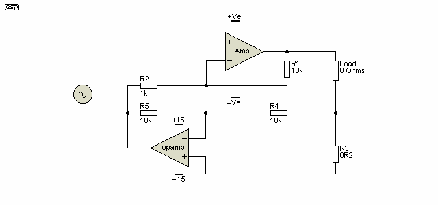
Figure 4 - Alternate (Non-Inverting) Negative Impedance Amplifier
The circuit shown in Figure 3 is quite practical, but it's inverting. One way to get around this is to use an opamp as shown above to simply invert the polarity of the current feedback. As before, this results in positive feedback, so as the load resistance (or impedance) is reduced, the gain of the amplifier increases. Needless to say, the opamp can also be configured as an inverter in front of the amp's input.
Performance is otherwise identical to that of Figure 3, and the impedance can be varied easily by changing the value of R4 or R5. I leave it to the interested reader to work out which resistor variations increase or decrease the output impedance. As noted, this is not a trivial exercise, and anyone who wishes to experiment must be prepared to deal with the potentially 'interesting' effects that negative impedance can create. Testing with a high powered amplifier is absolutely not recommended, as a little too much positive feedback can cause oscillation.
A limited amount of negative impedance also helps transformers give their best possible performance. This is covered in some detail in the article Transformers For Small Signal Audio, and includes measured results from a transformer driven from a NIC (negative impedance converter). The NIC used is based on that shown in Figure 3, but with protection against DC problems caused by the low resistance of the transformer winding.
There are also some test results obtained with a loudspeaker driven from various impedances in the article Effects Of Source Impedance on Loudspeakers. This is a pretty old article now, and I had to resort to taking a photo of the oscilloscope screen at the time, but the results are still valid.
This is not something I can recommend, and unless you are fully aware of the risks and are prepared to destroy stuff should something go wrong, then don't even attempt it. Negative impedance is usable with known loads that have little or no frequency dependent response variations. For loudspeakers, I suggest you forget that you ever read anything about it. 
There is one other topology that is commonly used to create a high impedance (current drive) output, and that's called the Howland Current Pump [ 1 ]. It has an advantage over the version I showed above in that the load is earth-referenced, and there is no need to have a fully floating load. While this can be important for laboratory work, it's not an issue with loudspeakers (for example) as they are already a floating load. For high-power systems, the Howland current pump has far more disadvantages than advantages, the most critical of which is stability.

Note: This description is for information only, and the Howland current pump is not recommended for any power amplifier. Resistor values are far too critical and even high stability types cannot be guaranteed to retain their value (within a fraction of one percent!) over time and temperature variations. As a laboratory experiment and for low current applications there's no problem with the circuit, but if driving a loudspeaker with a power amp that can deliver enough current to destroy the speaker driver, it's not something I would ever recommend.
The basic Howland circuit is shown below. While this circuit is very accurate (as good as the opamp, tolerance of the resistors used and the accuracy of the trim), it is limited to low currents. With 9,950 ohm (plus 50 ohms = 10k) feedback resistors as shown, and with (say) a ±15V voltage swing, the current is limited to 2mA. Not much use for audio power amplifiers.
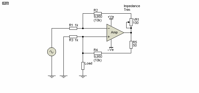
Figure 5 - Basic Howland Current Pump
This circuit is capable of sourcing/ sinking bipolar (positive and negative) current. If carefully trimmed using VR1 and assuming the use of 0.1% resistors throughout, it can have an extraordinarily high output impedance - at least within the frequency range where the opamp has sufficient gain. It's assumed that the opamp is a high performance type.
The 'improved' version can easily drive far more current, but because the resistor ratios are so great (10,000:1 in the circuit below) it is probable that it will be found to be temperamental if operated with even moderate output impedance. Actually, I'll rephrase that - it will be temperamental. The circuit can be trimmed to provide a wide range of output impedances, including negative impedance. Beware though - at close to infinite impedance with all resistances perfectly balanced, the circuit is extremely sensitive to small resistance value changes. Even a resistor change of 0.01%, large performance variations will occur. This is totally impractical for an audio system (for example).
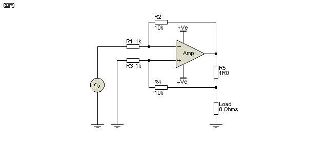
Figure 6 - 'Improved' Howland Current Pump
If R2 is made less than R4 the output impedance is positive, but less than infinite. The exact impedance can be adjusted by varying R2, but ensuring that it is always less than R4. This is stable and appears to have no bad habits, but only at fairly modest impedances. Because of the positive feedback loop, the overall stability of the circuit is far less predictable than the version shown in Figure 2. With the (exact) values shown, output impedance is about 10k, but a variation of only 1 ohm in any one of the resistors will make an enormous change. A 1% resistor value change can cause anything up to a 15% difference in output voltage, so an unacceptably temperamental circuit will be the result.
If one were to use this arrangement, I would not even try to obtain very high impedance - a sensible limit is up to perhaps 20 ohms, but even to achieve that the resistors must be very close tolerance. As an example, if R2 is 9.5k, output impedance is about 18 ohms. To achieve about 100 ohms output impedance, R2 has to be increased to 9.9k, only a 100 ohm reduction from the nominal 10k value. It's actually effectively 101 ohms because of the extra 1 ohm in the positive feedback path, but the difference is immaterial in reality.
To get negative output impedance, make R2 greater than R4, but be very careful - the circuit is extremely sensitive to even tiny variations - it's safe to say that using a Howland current pump for negative impedance is a really bad idea. It is simply too unstable when used this way.
While the Howland pump might seem like a good idea, the more traditional approach (Figures 2 and 3, positive and negative impedance respectively) to making a power amplifier with a defined output impedance is preferable and vastly more predictable because the feedback is tightly controlled without any need for extremely close tolerance resistors. Positive feedback is required when configured for negative impedance, but it must always be well controlled - not always possible with 'real world' loads.
For experimentation, a fully variable impedance amplifier is useful. Ideally, the volume will stay reasonably constant as the impedance is changed, but of course this is moot point when the load is a loudspeaker driver. Its impedance varies widely anyway, so even an amplifier that retained perfect amplitude stability as the impedance was varied will still give different results when loaded with the speaker. The following shows the basic circuit, and the power amplifier is simply shown as an opamp for simplicity. In reality, it will be a standard power amplifier, selected for your needs.
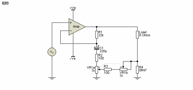
Figure 7 - Variable Impedance Amplifier
The 1k pot is dual-gang, and while an antilog pot would be nice, they are all but unobtainable. A linear pot will be acceptable, and the (theoretical) impedance range is from zero to about 46 ohms. A table of output impedance versus pot rotation is shown below, along with the output voltages. An 8Ω resistive load is assumed for all loaded voltage measurements.
| Pot Position | VOPEN | V8Ω | ZOUT (Ohms) |
| 100% | 61.5 | 9.05 | 46 |
| 90% | 32.6 | 8.7 | 22 |
| 80% | 23.0 | 8.5 | 13 |
| 70% | 18.4 | 8.4 | 9.5 |
| 60% | 15.6 | 8.4 | 6.9 |
| 50% | 13.9 | 8.5 | 5.1 |
| 40% | 12.7 | 8.7 | 3.7 |
| 30% | 12.0 | 9.0 | 2.7 |
| 20% | 11.5 | 9.5 | 1.7 |
| 10% | 11.2 | 10.2 | 0.8 |
| 0% | 11.1 | 11.1 | 0 |
The table shows the output impedance, calculated using the technique shown in Section 2 (Mixed Mode Feedback). It's apparent that the loaded output voltage does change, but not by a huge margin. Since the table shows the results with a purely resistive load, it should be fairly obvious that you will be able to hear the difference (both level and tonality) when a driver or complete loudspeaker system is used. Because almost all systems have a non-flat impedance, the audibility will be highly variable, depending on the loudspeaker used.
With the resistive load, the maximum loaded amplitude variation is 2.4dB (11.1V at 0Ω and 8.4V at 6.9 to 9.5Ω). The tonal variations will be far greater, with some loudspeakers being far more sensitive to source impedance than others. The benefit of the circuit shown is that you can listen to the speaker as you change the impedance. The most noticeable effects are almost always a sense of 'improved' bass (it's really just bass boost, often with very obvious peaking at resonance), and often an apparent 'improvement' in treble. Mostly, there's also a drop of midrange level (relative to bass and treble), and the result is almost never actually 'better', although it may seem so initially.
It's worthwhile to make a comment here about power compression in loudspeakers. This is a natural phenomenon that causes loudspeaker drivers to lose efficiency as the voicecoil heats up, and while it's generally considered a nuisance, it may be the only thing that prevents driver failure in a system that's pushed to the limits. Consider a speaker driver rated at 1,000W - very silly, but they exist in great numbers. If operated with a 1kW amplifier, the average power might be around 500W - assuming some clipping, and heavy signal compression at the mixer output.
After a short while, the voicecoil heats and its resistance rises, so less power can be absorbed from the amplifier. 3dB power compression is considered to be quite good (see Loudspeaker Power Handling Vs. Efficiency for more details), so the actual average power will drop to around 250W. There is one detail that it's worthwhile remembering ...
Power compression may well be the only thing that saves the speaker from failure !
As the voicecoil heats up, the power is reduced, and that alone prevents the temperature from continuing to rise until the voicecoil fails or sets the cone on fire. If the amplifier were to have current drive (and sufficient reserve power - aka 'headroom'), the power will increase as the voicecoil gets hotter, ensuring the demise of the loudspeaker. For this to be 100% effective at destroying the speaker, the amp's output impedance has to be somewhat higher than the speaker's impedance (at least 6 ohms for a 4 ohm driver).
Ultimately, the amp's supply rails limit the maximum power that can be delivered, but there are plenty of amps that are capable of destroying any loudspeaker ever made - especially very high power Class-D amps. It's probably fortunate that it's often somewhere between inconvenient to impossible to convert some Class-D amps to current drive without serious modifications.
If the amp were configured with negative impedance, as the voicecoil heats up the power will be reduced even further, increasing the apparent power (thermal) compression. The continued use of (close to) zero ohms output impedance is a requirement with modern very high power speaker systems, as it's probably the only thing that ensures that loudspeakers aren't destroyed routinely.
Power compression is very real, and if you do anything to 'compensate' (such as using a bigger amp and turning up the volume) driver failure is almost a certainty. Equipping amplifiers with partial current drive would be an excellent way to guarantee driver failures, because the voicecoil self-heating cannot protect the system from excess temperature. Unfortunately, the use of negative impedance has too many other problems, so it can't be used to help protect the drivers.
Note that positive output impedance is very common for guitar (and to a lesser extent, bass) amplifiers, but they are traditionally equipped with speakers that can handle the full output power when the amp is driven into hard clipping, so the output impedance cannot create a situation where the speakers get more power than they can handle safely. It's used as a tonal modifier, allowing the speakers to provide their own colouration to the sound, and is simply an extension of the situation with valve ('tube') amps, most of which have comparatively high output impedance.
This 'project' is not really a project at all (which is why it has also been included in the articles index), but more of a starting point for experimenters. The circuits shown will all work with 'real' amplifiers, but great care and considerable testing are needed to ensure that the results you actually obtain are providing a real benefit. Be very careful if you use IC power amps (LM3886 for example). Most are designed to run at a particular minimum gain, and may oscillate if the gain is reduced below the minimum recommended due to the current feedback. This is especially dangerous if the load impedance falls at high frequencies.
It is too easy to make a change such as shown here, and fully believe that the result is an improvement, where in reality (as eventually discovered after extensive listening and comparison) the opposite is true. While negative impedance may be found useful for horn compression drivers, it is unlikely (in my experience) to provide any benefit at all to cone loudspeakers. The benefits to compression drivers are also of dubious overall value.
Positive impedance can produce an improvement in bass response, but the cost can be high - boomy, over-accentuated bass around resonance, usually accompanied by a loss of definition. There will be more freedom for the speaker cone to waffle about after the signal has gone ('overhang'), and it is rare that a speaker driven by a higher than normal impedance will perform well without additional damping material in the enclosure.
There is no doubt that at output impedances in the order of 4 to 6 ohms your amp will sound more like a valve amp (but usually with less distortion), but it is up to you to decide if this is what you really want to do. The technique works well for guitar amps, as it allows the speaker to add its own colouration to the sound, which adds to the overall combination of distortion and other effects to produce pleasing results. For Hi-Fi the case is less clear, and experimentation is the only way you will ever find out for sure.
There have been many claims over the years that current drive is the best, and some may claim it's the only way to drive loudspeakers, as it reduces distortion and allows the speaker to work the "way it was intended". While there is some discussion of this on the Net (see [ 2 ] as an example), there is little real evidence that the benefits are anywhere near as great as claimed. Tests I've run show no improvement, but I admit that my test equipment is not really laboratory standard, so maybe I missed subtle effects? I don't think that I missed anything, considering that I've been messing with current drive for well over 40 years. All loudspeaker drivers are designed and manufactured based on the high probability that they will be connected to a voltage amp, not a current amp. While there does seem to be evidence that some distortion 'mechanisms' are reduced by current drive, there are so many other problems with it that no serious manufacturer has ever bothered.
A claim that you may see is that current drive eliminates power compression in loudspeaker drivers, because the change of voicecoil resistance doesn't affect the amplifier current. While this is true in theory, in reality as the voicecoil heats you actually get more power with pure current drive, thus guaranteeing that the driver will be destroyed without human intervention. This can be mitigated by using modified impedance, but why? The reduced power delivered to speakers when they get hot is often the only thing that saves them from destruction, and current drive ceases as soon as the amplifier clips anyway.
Naturally, there are a great many outrageous and/or ill thought claims made by the ever present audio nut-cases - 'new' and 'revolutionary' are but two of the silly terms used to describe what they have found. Well, sorry chaps, it was actually never lost, is anything but new, and isn't even a little bit revolutionary. Discoveries in this area are pretty much old-hat now, because so many people have played with current drive for so long.
Many full-range loudspeakers are likely to sound better with current drive (extended bass and treble in particular), but cabinet size, internal damping and (more than likely) parallel filters have to be optimised to account for the loss of amplifier damping and to minimise peaks or excessive high frequency output. Using mixed mode amplifiers can allow a speaker to work at its best in a larger than normal enclosure, because the use of a defined source impedance affects the Thiele-Small parameters.
It is also possible to adapt a bridged amplifier to use current drive, but there are some interesting obstacles to overcome. This will not be covered here unless there is overwhelming interest.
I've been using current drive in various forms since the early 1970s, with typical output impedances of up to 200 ohms. Over the years many people have heard what they initially thought were huge improvements in the sound of individual drivers and/or complete systems. In reality, only some effects were ultimately found to be useful, and almost identical results can often be achieved with fairly basic equalisation. This doesn't negate the process though, and as you'll see in the next section, there are some who think that current drive is worthy of taking out a silly patent on a process that is already well known to a great many people, and for a very long time.
For myself, I still like playing around with variable impedance. I have a 3-way active test amplifier with two channels that can be varied from -8 to +32 ohms, and I use it regularly - it drives my workshop 3-way active sound system. It has been used in the past to test many, many drivers, enclosures and compression drivers + horns, and it remains a useful tool for testing, despite its age (it was built sometime in the 1980s!).
Useful tool, major improvement in loudspeaker driver performance or just a fun thing to play with? I leave it to the reader to decide  .
.
Some Mothers Do 'Ave 'Em ¹
Interestingly, some lunatics from the Tymphany Corporation in the US have decided that they are entitled to a patent on the general ideas shown here. Despite the copyright notice below that specifically prohibits commercial use, and without asking permission or thinking rationally, Tymphany has used this article as a reference in the patent, and the US Patents Office granted it! Well apart from the fact that the idea is common knowledge, their idea is quite obviously not appropriate for a patent - everything they claim has been done before. They do rabbit on about using DSP to tailor the amp behaviour depending on frequency, but so what? Others have done the same things long ago, although without the DSP in most cases.
That the patent would fall like a house of cards in a court of law is quite obvious. I for one cannot believe the gall and audacity of anyone to obtain a patent based on material that fully describes the patent in prior art and/or websites. In typical patent verbiage, they basically claim that the patent is for a mixed-mode amplifier (as shown in Figure 2). If you want to read the patent (so that it may be violated in full and without fear of recrimination) I have a copy right here. Enjoy 
Note 1 With appropriate apologies to the 1970s British TV series of the same name.
 Main Index
 Projects Index
 Articles Index