
|
|
| Elliott Sound Products | Rectifiers, Selection & Usage |
 Main Index
Articles Index
Main Index
Articles Index
While there are several pages on the ESP website that describe various rectifiers as used in power supplies, this page has been added to show the different rectifier topologies that may be found in any number of products. Each (except the 'voltage clamp') uses the same input and load current for ease of comparison, so it's easier to see the relationships in an 'ideal' case.
In reality, the transformer will add series resistance due to the winding resistance of the primary and secondary, but this has not been included because it makes the comparisons less clear. Nevertheless, it's always present, and the peak input current allows you to calculate the voltage loss for your application. A 'token' 1Ω resistor is used in series with all voltage sources to make the comparisons more sensible.
All waveforms shown assume 50Hz mains, a source impedance of 1Ω, and an AC voltage from the transformer of 50V peak (35.4V RMS). Where a transformer has a dual winding, each half of the winding has the same impedance (1Ω) and voltage. The output load resistor is scaled as needed for an output power of (close to) 20W. For example, if the DC voltage is 50V, the output resistance will be 125Ω, giving an average current of 400mA. The filter capacitance is adjusted to that value which produces an output ripple voltage of about 2V peak/peak. Some variations are inevitable, and especially so when you have to use values you can get rather than the values shown in the drawings.
It's not especially easy to ensure that the output power and/or ripple are exactly as intended, so there will be some small variations seen in real life. However, these are less than the expected difference due to mains voltage which can vary by ±10%, and sometimes more. The purpose of providing a reasonably consistent load power is to ensure that comparisons are as easy as possible, but there will be inevitable conflicts so it's important that the reader understands the application.
While a simple table is provided for each rectifier type, these are idealised and only represent the performance with the source and load impedances shown. Diode voltage drops are based on an 'ideal' diode, which has the normal 0.65V forward voltage, but no appreciable internal resistance. Input current for any rectifier depends on the total source impedance, so the values shown in the examples will be different in reality. The actual current depends on the transformer, diodes and load current. Input/ output relationships are also affected by component impedances, but those shown give a representative idea of what you can expect. All DC voltages and currents shown are average, and AC is RMS (except for half-wave which shows the average value of the AC).
Note that 1.414 is the square root of two ( √2 ), and assumes an undistorted sinewave. Reality will be different. 'PIV' is peak inverse voltage (the maximum blocking voltage for a diode).
Peak voltage = Vin(RMS) × 1.414
In the drawings, I have shown a voltage source rather than a transformer winding. This was done to keep the drawings consistent, and make everything as clear as possible. The voltage source and source resistance (Rs) are considered as a single part, and are maintained for all rectifier types. A transformer winding can simply be used in place of these two parts in a 'real' circuit.
If you are unsure about transformers, then please read the Transformers - Part 1 article (along with Part 2), and/ or Power Supplies for more complete descriptions and detailed analysis. This article is intended only as a primer to the various rectifier types that are in common usage, and it is not intended to replace any of the other material already published on the ESP site. In all cases, the input voltage is deemed to be the generator voltage (ignoring the series resistance), and is determined by ...
The 'load power factor' figure is derived from the actual load power (in the load resistor) and the input VA (RMS voltage × RMS current). This is provided as a comparative figure so you can see the differences in the circuits as shown (the ideal power factor is unity (1), but this is never achieved with any simple rectifier circuit). In reality, the figure will vary depending on the actual source resistance/ impedance. This will also cause the voltages and currents to differ from the values given. As the source impedance is increased, peak current (in particular) is reduced, as is the output voltage.
The power factor is important because it tells us that if you need 100W DC output, a transformer of at least 180VA is required regardless of rectifier type, or it will be overloaded. While short-term overloads will not cause any problems, if sustained the transformer will overheat and fail. If one were foolish enough to use a half wave rectifier, the transformer will overheat anyway, due to the high DC component in the windings which will cause saturation, massive over-current, and guaranteed failure.
Peak voltage = Vin(RMS) × 1.414 (assuming an undistorted sinewave input).

When any power supply using diodes feeds a filter capacitor, the diodes can only conduct when the peak AC voltage is greater than any voltage remaining across the capacitor. This means that the AC current waveform is distorted (no longer a sinewave), and the peak current has to be great enough to re-charge the filter capacitor, and supply the load. Each explanation below indicates the peak current, and it's always much greater than the average. This causes relatively poor transformer utilisation, since current flows for much less than the full half-cycle period (10ms for 50Hz mains, 8.33ms for 60Hz). The diode conduction period is rarely more than 2-3ms, and generally far less.
As an example, if the peak diode current is 3A and the transformer plus diode series resistance is 1Ω, the peak voltage is reduced by 3V, plus the diode's forward voltage (0.75V for each conducting diode). This means that a transformer with a 50V peak output (35V RMS) cannot provide 50V DC output. For a bridge rectifier, the maximum DC level with 3A peak output is 45.5V, with the average being a bit less because of superimposed ripple.
Please be aware that the above note includes a number of simplifications, and the reality can be slightly different. It's outside the scope of this article to go into great details though, so I suggest that you also read the articles on power supply design and transformers. While the process of rectifying an AC voltage seems fairly straight-forward, it's actually quite complex when examined closely. For most power supply applications, a small inaccuracy is of no consequence. Normal mains voltage changes far more than any small error due to simplifications made, and few transformers provide their exact 'name plate' voltage because it depends on the current drawn.
Note that 'choke input' filters are included, but only 'in passing' as it were. These are a special case, and are rarely used today for 'linear' (i.e. mains frequency) power supplies. Also, be aware that the term 'linear' is really a misnomer when describing rectifiers. The current waveform is not linear (i.e. not sinusoidal), but consists of brief pulses of current when the input voltage exceeds the voltage across the smoothing capacitor. It stands to reason that current cannot flow when diodes are reverse-biased, and this is the situation for well over 70% of the input voltage waveform. Current typically flows for around 15% or less of each half-cycle. For example, the diodes may conduct for 1.5ms in each 10ms half-cycle (for 50Hz mains). Using a choke input filter changes this, but in a somewhat counter-intuitive way.
This is the simplest of all, and also the least desirable. It is not recommended for anything. There is no need to use a half wave rectifier given the low cost of suitable diodes, and because it introduces DC through the transformer winding(s), it's surprisingly easy to cause transformer saturation that can lead to the demise of the transformer due to over-temperature.
Figure 1 - Half Wave Rectifier
Current flows only when the transformer's secondary voltage is more positive than the remaining voltage across the filter cap (C1). Because the current is unidirectional, this creates DC through the secondary. With a toroidal transformer, you may only need a few 10s of milliamps to cause serious problems.
Output ripple is at the mains frequency. Required diode PIV is twice the peak input voltage, so 50V peak input requires 100V diodes (minimum). The input current is 4.75A peak, with an average value of 444mA DC. Average DC output is 44.5V DC with 19.7W in the 100Ω load. The voltage is lower than expected because the high peak current causes a significant voltage loss across the 1Ω source resistance. Capacitor ripple current is 4.3A peak (1.22A RMS).
I recommend that this rectifier is never used for anything that demands more than a (small) few milliamps of load current (and that is of dubious value to anyone). See Half-Wave Revisited to see some test results and oscilloscope waveforms.
Input Current 445mA average (1.3A RMS, 4.75A peak) Output Current 445mA Capacitor Current 1.22A RMS Load Power Factor 0.435
I consider half-wave rectifiers to be an abomination, and as such I strongly suggest that you never use them if there's any other option available. It's rare that you can't use a bridge rectifier, with the only exception that comes to mind being valve (vacuum tube) power transformers that have a tap for the negative bias supply. Because only one tap (almost never a separate winding) is provided, there is no choice, as it's already been made when the transformer was designed. That doesn't mean I like it, and given the cost of the transformers it would be nice if a separate winding was provided to allow a 'proper' rectifier and filter.
The 'traditional' full wave rectifier was popular in the valve (vacuum tube) era, as it was easy to do with a single rectifier valve with a common cathode and two anodes. However, it requires more wire on the transformer, which has to be thinner than desirable so the wire can physically fit into the transformer winding window. While convenient, it is no match for a bridge rectifier which achieves the same result with a single transformer winding, which will typically have a winding resistance of less than half that of each winding shown.
Full wave rectifiers are common again in switchmode power supplies (SMPS), because the number of turns needed is small, and it's cheaper to add a few more turns to a high frequency transformer than to buy additional high speed diodes. It also lends itself to other rectification schemes, such as synchronous rectifiers (using MOSFETs) that have very low losses.
Figure 2 - Full Wave Rectifier
There is no net DC in the transformer windings. Each half of the winding has a significant DC component, but the two windings have opposite phases so the DC component is cancelled. The full wave rectifier is commonly found in pairs, and used with opposite diode and capacitor polarities to generate positive and negative supply voltages at the same time. This then becomes a full wave (dual supply) bridge rectifier and is shown further below.
Output ripple is at twice mains frequency, diode PIV is twice the peak input voltage. 50V peak input requires 100V diodes (minimum).
Note that C1 is almost half the value needed for a half wave rectifier, with peak and average currents all reduced substantially.
Input Current 2 × 230mA RMS (3A peak) Output Current 460mA Capacitor Current 938mA RMS Load Power Factor 0.65
The bridge rectifier is full wave, and makes maximum use of the transformer winding. This is the most efficient rectifier in common use, and diode bridges are readily available with many different voltage and current ratings, suitable for most needs for general purpose power supplies. There is no net DC in the transformer winding, as current is delivered symmetrically, via two diodes in series for each polarity. This is the preferred rectifier for the vast majority of applications, as its performance is generally hard to beat with other topologies. The bridge is sometimes known as the Graetz circuit or Graetz bridge [ 2 ].
Bridge rectifiers are probably one of the most common of all, and can be made with discrete diodes or purchased as an encapsulated module. Voltage ratings range from around 50V up to 1kV or more, with continuous average current ratings from 150mA to 1,000A. Peak current ratings can be a great deal higher - even 1A diodes can handle a non-repetitive surge current of 30A or so (albeit for less than 10ms). For serious power supplies (power amplifiers, bench power supplies, etc.), a 400V, 35A bridge module is convenient, extremely robust and usually inexpensive. This is my recommendation for all such applications.
Figure 3 - Bridge Rectifier
While the presence of two diodes in series is a small nuisance, the voltage loss is generally less than 1V compared to a full wave circuit. In reality, this is more than compensated by the fact that the transformer winding is fully utilised for positive and negative half-cycles, so there is more commonly a net increase of output voltage for a given output voltage and current with any given transformer.
Output ripple is at twice mains frequency, diode PIV is the peak input voltage. 50V peak input requires 50V diodes (minimum).
Peak input current is just over 3A (1.04A RMS) for an output current of 453mA (20.5W in the 100Ω load). Capacitor ripple current is 2.6A peak (938mA RMS).
Input Current 1.04mA RMS (3A peak) Output Current 454mA Capacitor Current 953mA RMS Load Power Factor 0.57
This is another circuit that's hard to recommend. Despite the name, there is no net DC in the transformer winding, but input current is a lot higher than you may expect. Because the input is delivered via a capacitor, there can be no transformer DC. C1 passes positive peaks when the voltage is greater than that across C2, and recharges during negative peaks. The voltage rating for C1 is the same as the peak AC voltage (50V for the example shown). C2 must be rated for twice the peak input voltage, because it's across the full output (roughly 92V for the circuit shown). The input source and output share a common connection that may be useful. A full wave doubler uses the same number of parts but has lower ripple (for the same capacitor size), draws a lower peak current from the source, and is the preferred option for most applications.
Figure 4 - Half Wave Voltage Doubler
Output ripple is at the mains frequency, and diode PIV is twice the peak input voltage. 50V peak input requires 100V diodes (minimum). Beware of capacitor ripple current, which is around 3A peak (1A RMS) for an output of 91V DC (at 227mA output current).
The two capacitors do not have to be the same value. C1 can be smaller than C2, which does not affect the output ripple voltage. However, if C1 is too small the output voltage will be limited due to the capacitive reactance (impedance) of the capacitor.
A half wave doubler can be a useful addition to an off-line (powered directly from the mains) PSU, but these cannot and must not be used to power anything with user-accessible terminals. This type of supply is covered in the article Small Power Supplies article, and will not be discussed further here.
Input Current 1.04mA RMS (3A peak) - Also applies to C1 Output Current 227mA Capacitor Current 953mA RMS Load Power Factor 0.58
This is a useful circuit that's not uncommon with valve amplifiers, and it's a recommended rectifier provided you understand the limitations. There is no net DC in the transformer winding, but input current is again higher than you may have expected. It outperforms the half wave version in every way, but lacks a common connection between the source and output, which may be important in some circuits.
Figure 5 - Full Wave Voltage Doubler
Output ripple is at twice mains frequency, diode PIV is twice the peak input voltage. 50V peak input requires 100V diodes (minimum). Peak input current is just under 3A for an output current of 228mA (20.8W in the 400Ω load). This arrangement has the advantage that a half voltage output (about 46V DC) is available at the capacitor centre tap, but the ripple here is at mains frequency.
The centre tap 50Hz ripple voltage is 2V peak-peak with no load, and it increases (perhaps dramatically) if any current is drawn. Both caps require a working voltage of half the total output voltage (50V DC minimum for this example), because they are wired in series. Capacitor ripple and peak currents are the same as for the half wave doubler (711mA RMS, 2.8A peak). Input current is 3A peak (711mA RMS).
Output ripple is at the mains frequency, and diode PIV is twice the peak input voltage. 50V peak input requires 100V diodes (minimum).
Input Current 1.06A RMS (3.05A peak) Output Current 230mA Capacitor Current 712mA RMS Load Power Factor 0.56
If used for a dual supply (such as ±15V after regulation, be aware that the ripple is at mains frequency on both outputs. This means that filter capacitors need to be larger than with a full-wave, centre-tapped bridge (shown next). While it's now necessarily a problem, it is something you need to be aware of.
This arrangement is simply a pair of full wave rectifiers, with each having opposite polarities for the diodes and capacitors. Because it commonly uses a standard encapsulated bridge rectifier, it's more commonly known simply as a dual supply bridge rectifier. The performance of each polarity is (almost) independent of the other, but losses in the transformer apply to each output, even if one has no load. This is not a limitation in real world applications, and the outputs can be considered to be independent for all practical purposes.
Figure 6 - Full Wave, Dual Supply Bridge Rectifier
Output ripple is twice the mains frequency at each output, and diode PIV is the sum of the two windings (100V for the example shown).
Input Current 2 × 1.06A RMS (3.05A peak) Output Current 2 × 460mA Capacitor Current 953mA RMS Load Power Factor 0.56
The next class of rectifier is the voltage multiplier. I've elected to draw the tripler circuit using the 'traditional' format, with the diodes and caps forming a triangular pattern. This was done so the circuit is immediately recognisable, as it's the most common way these circuits are drawn.
Multipliers are normally only ever used when particularly high voltages at very low (or almost no) current is needed. Although a voltage doubler is technically a voltage multiplier, it's generally not classified as one because it is much more commonly used for power applications (although low power doublers are also common in metering circuits). The most common use for voltage multipliers was the 'tripler' circuit that was standard with all CRT colour TV sets and monitors. The tripler generated the acceleration voltage for the final anode of the cathode ray tube.
Voltage multipliers are also used to generate the polarising voltages for electrostatic loudspeakers, Geiger-Müller or photo-multiplier tubes and many other circuits that need high voltage at low current. It's common to drive a multiplier from a higher frequency than the mains. In CRT sets (PAL system) the frequency was 15,625Hz (the horizontal deflection frequency), but higher frequencies are not uncommon. This allows smaller capacitors to be used, but the diodes must then be fast or ultra-fast types.
Figure 7 - Voltage Tripler
Although a tripler is shown, any multiplication desired can be created by adding more diodes and capacitors. The voltage across C1 is the same as the peak input voltage, but there is double that voltage across each of the others. All diodes are subjected to twice the peak AC input voltage. The table for operating conditions is not relevant for voltage multipliers, but the circuit shown draws only 1.9mA RMS, but that's for a rather miserly 147µA of output current. This gets worse as more stages are added. While more current can be drawn, the capacitors need to be larger or you can accept a lower voltage.
To extend the multiplier for more output voltage, simply duplicate D2, C3 and D3 (one 'stage'). Each additional stage boosts the output voltage by the peak-peak voltage from the generator, in the case shown that adds 100V with every new section. Extending to four sections will give an output approaching 250V, but the output starts to sag badly with a lot of stages. For example, five stages should give 350V, but the voltage will be only around 320V if the 1MΩ load is maintained.
You will regularly see this circuit referred to as the 'Cockcroft-Walton' voltage multiplier, so named after the gentlemen who invented it in 1932 [ 2 ]. It is not an efficient way to get a high voltage, but it's cheap and works extremely well if you don't need much current. If you do need appreciable current, then this is not the circuit to use.
With the values shown (including the 1MΩ load), output ripple voltage is less than 1V peak-peak.
There are many variations on the basic multiplier (including a full wave version), but these will not be covered further here.
The final rectifier is included because it's so common, although most people will never get to play with one (and it's not recommended because they are deadly and have killed quite a few people). The voltage clamp 'rectifier' is used in microwave ovens, to supply the cathode voltage for the magnetron. The anode is earthed/ grounded, so the supply voltage is negative. Unlike the other circuits shown here, the voltage and current are set to those that may be used in a 1kW microwave oven.
Figure 8 - Voltage Clamp
The clamp can't really be considered as a 'normal' power supply circuit because the output is pulsating DC, with the peak voltage (close to) equal to the full peak-to-peak voltage from the MOT (microwave oven transformer), with the 'positive' peaks clamped at zero volts (± a few diode voltage drops). The average DC voltage and current outputs are shown, and it's worth noting that the input VA rating gives an output power factor (as shown for the other examples) of 0.56 - much as for any other rectifier. That means that the transformer has to supply 1.96kVA for an output power of 1.12kW.
The magnetron is not modelled in the above, and the load is just a resistor. It's not a perfect analogy, but is sufficient to demonstrate the workings of this arrangement. The magnetron actually gets a voltage that varies from zero to -6.9kV at the mains frequency. It's crude, but in reality it works very well as countless microwave ovens use it. Most modern versions use a switchmode supply ('inverter') instead, because it's a lot lighter. Reliability of the 'old' method is very high, something that isn't necessarily the case with an inverter supply.
Multi-phase rectification is actually more common than you might think, as it's standard in most car alternators. While this isn't something that normally interests most (audio at least) hobbyist constructors, it's still important because it's such a well used technique. The three windings generate alternating voltages that displaced by a 120° phase angle, and these are rectified using a modified bridge. Anyone who's ever dismantled a car alternator will have seen the six press-fit diodes buried into the aluminium casting at the back of the alternator, and now you can see exactly how they are wired. Note that in some designs there may be a separate set of diodes for the field winding, so you may see anything from six to twelve diodes in all.
The three windings are shown wired in Delta (Δ), but the 'Star' (aka 'Y' or 'wye') connection is also shown. The Star connection has a neutral point, which is standard for electricity distribution, but it doesn't have to be utilised (it's shown as 'N.C.' meaning no connection). A balanced (equal current in each phase) 3-phase system works just as well with or without the neutral. A Star connection requires fewer turns than Delta as the required voltage is lower, but overall efficiency is generally similar. When Star connected, the voltage between source outputs is √3 × RMS voltage referred to the neutral. For the circuits shown, each Star generator outputs 6.53V RMS, and the Delta generators output 11.31V RMS. The peak voltages are shown on the drawing.
A Star connected alternator (or transformer) has output voltages that are a combination of the voltages from any two adjacent sources. The voltages between any two outputs have to be determined by vectors for Star connections, because of the 120° phase difference (which is where the '√3' term comes from). In Delta, the voltage is between any two points is that of each individual generator, since they form a series 'string' of sources, joined to form the complete Delta formation.
Figure 9 - Three-Phase Bridge
The voltages and load resistor have been changed in this circuit to match those normally found in a car's electrical system, but the load is arbitrarily set at 5Ω to provide a sensible current. A car's electrical system can present a much greater equivalent load, with a battery charging current of 20A or more. Note that only the rectifier and source windings are shown, as the field (aka exciter) winding, slip rings and regulator are not a direct part of the rectifier itself.
For automotive use, the operating frequency depends on engine speed, and may be as low as 8Hz (500 RPM), rising to 80Hz (5,000 RPM) or more depending on how fast the engine is revving, and the relative sizes of the engine and alternator pulleys. These are not relevant to the circuit as shown, but the alternator must obviously be designed to handle the speed range encountered for any given setup within the vehicle's systems.
Although there is no capacitor (or battery) at the output, the ripple is only 2.1V peak-peak (about 640mV RMS) because of the overlap between the three phases and the full wave rectification. In large systems, the relatively low ripple voltage means that filtering may not be required at all. The ripple frequency is six times the input frequency, so with 50Hz (for example) the ripple is at 300Hz. In some cases there may be more than three phases - six is fairly common, but 12-phase systems also exist. A 6-phase system can be produced by combining Star and Delta windings with 12 diodes. Output ripple is then 600Hz with a 50Hz supply, and for an equivalent to that shown above has only 480mV peak-peak (156mV RMS) ripple with no filtering.
Multi-phase rectifiers are also common in industrial systems, powering everything from variable speed motor drives, high power radio and TV transmitters, to electric trams and trains. So, while not a technique that many audio people will encounter, it would have been remiss of me not to include multi-phase rectification in an article that describes rectifiers in general.
While these 3-phase systems are common for power distribution and industrial applications worldwide, this article is not about 3-phase systems, other than the info shown above. If you want to know more, there are countless websites that describe 3-phase systems in detail, and this is not the place to expand on a topic that's not really relevant to the purpose of this article.
The reason for the re-visit is that I didn't want to break the 'flow' of the article by introducing specifics into this one rectifier type. Countless on-line articles say it's a poor choice, but only a few I found even mention transformer saturation (and some so-called 'engineers' even deny that it can happen!). This is the single most important limitation, because it's easy to destroy a perfectly good transformer by trying to simplify a design to its minimum. I tested a 200VA E-I core transformer, with 2 × 28V secondary windings. The secondary current rating is a bit over 3.5A RMS at full power. This is probably not your typical transformer that would be used with a half wave rectifier, but it has plenty of scope for testing. The no-load voltage from the transformer was 62V when I ran these tests.
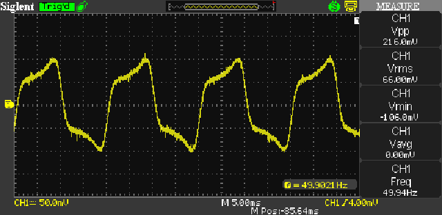
Figure 10 - Transformer Magnetising Current
With no load, the transformer draws a magnetising current of 66mA RMS. This is shown above, and it's pretty much what we expect from a transformer of this size and construction. I used a 270Ω resistor as the load, and that increased the total current to 112mA. Note that the measurement shown as 'V RMS' is actually 'A RMS' because I'm using a 1A = 1V current monitor.
Then I added a diode in series with the 270Ω resistor to create a half-wave rectifier. Average DC output current with this arrangement is about 102mA. The next trace shows the transformer primary current with this rather small DC load (after all, it's only 100mA average from a 3.5A transformer).
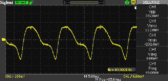
Figure 11 - Saturated Waveform Due To Rectifier (270Ω Load)
The input current has doubled, rising to 112mA RMS, even though the RMS output current is only 0.7 of that drawn by the 270Ω resistor alone. It takes little imagination to work out that increasing the DC a bit further will make matters far worse, and indeed, this is shown in practice. If the load resistance is halved (135Ω), the primary current increases further, to a rather scary 172mA.
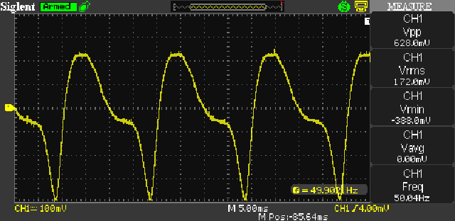
Figure 12 - Saturated Waveform Due To Rectifier (135Ω Load)
The final waveform is shown above, and transformer saturation is quite obvious. The asymmetrical waveform is a dead giveaway that something is wrong, and it's not something that you normally ever want to see (and this is definitely no exception). So, using a half wave rectifier is not only very inefficient, but the DC component causes transformer saturation at surprisingly low current. The situation is actually not as bad with small (less than 10VA) transformers, because they already have very poor efficiency (some barely increase their primary current if the output is shorted!).
Had this same test been done with a toroidal cored transformer, the results would have been a great deal worse, because they are utterly intolerant of asymmetrical loads, and have a much sharper saturation limit. It's worth noting that most electrical regulations now prohibit half wave rectifiers, because they produce even harmonics of the AC waveform and introduce asymmetry which creates a net DC component. I'm not the first to report on this, but unless you know what to search for, you probably won't see any reference to saturation in most explanations.
The effect is real, easily demonstrated (as seen above) but only spoken about in hushed voices at the end of long, dark corridors with 'Beware of Lions' signs posted at regular intervals. Ok, that may be a bit far fetched, but you get the point. 
This is a 'late entry' to this article, and was added because these filters have regained popularity - in switchmode supplies. They were once used in some 'high-end' valve amps, but generally fell from favour due to the size and cost of the 'choke' - an inductor. The main advantage is that instead of the filter capacitor charging only in short bursts, the charge time is only slightly less than a full half-cycle for each polarity. The 'off time' (when no diodes are conducting) can be as low as a few hundred microseconds, even with 50Hz mains. Unlike any of the other rectifier/ filter combinations discussed, the diodes must be high-speed types.
The output voltage is lower than a capacitor-input filter, but that in itself isn't a problem, as it only requires that the transformer has a higher voltage secondary. One interesting fact is that the primary current is close to being a squarewave at high current. It's not a 'true' squarewave, because there will be some residual of the AC input superimposed. This is likely to be unexpected by most people. It's probable that few hobbyists (and likely few professionals as well) have noticed this, as not many folk use a current monitor, such as those described in Project 139 and Project 139A.
Figure 13 - Example Choke Input Filter
An example is shown above, using the same AC input, rectifier, load and filter cap as the Figure 3 circuit. I ignored the resistance of the inductor for this example, but it's real, and cannot be ignored in a real circuit. The resistance value depends on the application, and for the Figure 13 example it needs to be less than 1Ω. The resonant frequency of the inductor and capacitor must be (much) lower than the lowest frequency of interest. This is determined by the formula ...
f = 1 / ( 2π × √ ( L × C ))
All inductor input filters have a common problem, in that there is always resonance, and when power is applied the voltage will overshoot the expected steady-state value by an amount that depends on the load current. In general, you should use the largest inductor you can, but this poses a serious problem. High inductance means many turns of wire, and that increases the resistance. It also means that the iron core will be subjected to a very high unidirectional current - it's DC. The flux must be kept below the saturation point of the core, so it requires a substantial air-gap. These factors combine to mean a very large, heavy and expensive component.
The alternative is to use a 'swinging' choke. These are deliberately designed so they will saturate, so the inductance is high at low current, and reduces as more current is drawn. These are a 'special' case, and the design process is not straightforward. It's quite likely that most were determined empirically when they were more common, as this would have been fairly easy to do. There's some more info available on the Valve (Vacuum Tube) Amplifier Design Considerations - Part 2 (section 6) page.
I don't intend to go into great detail with these, because they are irrelevant for solid state amps, and somewhat impractical for valve designs. When used with switchmode supplies the operation is somewhat different, as the inductor/ capacitor is set up to act as a PWM filter. The DC output is dependent on the mark-space ratio of the PWM waveform, in exactly the same way as for a PWM (Class-D) amplifier. The only difference is that the output is DC, not AC (audio).
Changing the value of the inductor (within reason) doesn't change the DC voltage, but there is a resonant interaction with the filter capacitor. For example, you could use a 100mH inductor with a 2,000µF capacitor, which has a resonant frequency of 11.2Hz. Any load that varies will cause the resonant circuit to 'ring' at the resonant frequency, causing large output voltage variations. Choke input filters are 'sub-optimal' for any application where the current changes quickly. They do have much better steady-state regulation than the more common capacitor input filter, but that disappears when you have a rapidly changing load current.
As a result, it's not possible to recommend using choke input filters with mains frequencies for low voltage supplies, because the requirements are in serious conflict. When carefully designed, and with a reasonably constant load, they are more efficient than a 'traditional' capacitor input filter, and transformer utilisation (output power vs. VA rating) is better. A capacitor input filter means that for a 100W nominal output, the AC input will be around 200VA, but a choke input filter will reduce that to about 140VA. However, the saving on the transformer is more than offset by the cost of the inductor. Choke input filters also require a bleeder resistor to maintain regulation if the load draws little or no current. This can be a real surprise when you leave it out and measure the full AC voltage times 1.414 unloaded.
A 35V transformer will provide 45V DC with a capacitor input filter, and around 25V DC (VAC × 0.8) with a choke input filter under load. Without the bleeder, you'll get 42V DC with no load, because the inductor isn't doing anything - without current, it's just a large (and heavy) resistor. You can estimate the minimum value of the inductor by dividing the DC voltage by the bleeder current in milliamps. If you expect 25V with a 100Ω bleeder (250mA and 6.25W) the minimum inductance is 100mH.
Figure 14 - Current Waveforms For Fig.13 Choke Input Filter
It's instructive to look at the current waveform in particular. With the 300mA load (100Ω load resistor), the input current is 377mA, and the capacitor current is reduced to 529mA. Compare that with the values shown for Figure 3, where the capacitor current is more than double the DC current. The AC current waveform is important, and it's easily seen that the transition from positive to negative (and vice versa) is very fast, so high-speed diodes are essential.
This is a very short overview of the rectifying element itself - the diode. Over the years there have been many advances in diode manufacture. The earliest diodes were used in 'crystal sets' - personal radio receivers, with the 'diode' being a crystal of Galena (Lead Sulphide), as well as several other substitutes. These could only work at very low voltage and current, and could not be used for power rectification.
Mercury arc rectifiers (1902) were the first high voltage, high current (>500A was common) power rectifiers, using a mercury cathode and multiple anodes. These were used in the early days of electric trains and trams, typically providing 1,500V DC at hundreds of amps. They were also common in industrial applications. They were not suitable for low voltages.
Valve (vacuum tube) rectifiers started with the Fleming valve (1904), and were the only satisfactory medium/high voltage, low current rectifier suited to consumer goods. They remained the main type of rectifier in radios, TV sets and other products until the 1960s, when silicon diodes became readily available in both high voltage and high current versions.
One of the first rectifiers that was usable at low voltage was based on copper oxide (1927). These have a very low reverse voltage (~2.5V max) and a fairly low forward voltage, but are not very efficient. Even medium voltages required a stack of copper oxide diodes, along with a substantial heatsink for each junction.
Selenium rectifiers came along in 1933, and offered many advantages over copper oxide. They are still fairly low voltage (20-25V reverse voltage) and not very efficient, with a 1V forward voltage drop. These were also used in large stacks (and again with substantial heatsink tabs at each junction) for battery chargers and other low voltage, high current applications.
Germanium diodes have a low forward voltage, but were nearly all of 'point-contact' construction, and were therefore suited to low current, low forward voltage applications. They were used extensively as detectors in early transistor AM radios (which also used germanium transistors). They are still available, but supply isn't very reliable. Germanium diodes are also useful for use in metering amplifiers, where the low forward voltage is useful to ensure high linearity.
Silicon diodes are the bulk of all rectifiers used today. They include Schottky diodes (very high speed, and a relatively low forward voltage, but limited peak reverse voltage), Silicon carbide (SiC), as well as many other variations (most are not relevant to the topic of power rectification). Modern silicon diodes are available in almost any voltage/ current configuration you are likely to need, from a small DC power supply up to providing DC for electric trains and other high power DC requirements. Getting useful historical info is very difficult, but by the 1960s, few commercial products used anything else - including most valve equipment. (I built my very first guitar amplifier in the 1960s - it used valves, but had silicon diode rectifiers.)
High-speed and/ or 'soft-recovery' diodes can be used with mains frequency rectification, and are common in switchmode power supplies. They are also necessary if you use a choke-input filter, even at 50/ 60Hz. These diodes are characterised by their rapid transition from 'conducting' to 'not-conducting', which minimises switching losses in circuitry that has rapid transitions (switchmode power supplies for example. While they aren't necessary for 'normal' rectification with a 50/ 60Hz supply, they do no harm and may reduce conducted emissions. They are more expensive than 'ordinary' diodes with the same voltage and current specifications.
Entire articles have been written on this topic, so a search will find more if you are patient.
This article is intended as an introduction to the various rectifier types in common use. The exception is the half wave version, which as already noted is a very poor choice. While many authors will point out that half wave rectifiers are a poor choice due to the high ripple and the need for a much larger than normal capacitor, few seem to have noticed that the DC component in the transformer will cause saturation, greatly increased magnetising current and transformer overheating.
The other rectifiers shown are all ok to use for anything you need, and it's simply a choice based on the transformer voltage and the requirements of your circuit. Half wave doublers aren't a good choice though, as the ripple voltage is at the mains frequency, rather than double the mains frequency with most others described.
As already noted, this is not a full description of power supply design techniques, which is described elsewhere on the ESP website. The information here is to let you see the options and make comparisons between the topologies. To assist you in this, each supply is set up to develop the same power in the load resistor, and you can see the input and capacitor current requirements for each example. In use, these will usually be different from the values shown, not because of any error, but because the source impedance can have a large influence on the peak current. This is especially true for supplies that have a larger than normal transformer and filter caps. Average and/ or RMS values should normally scale fairly linearly as the supply is made bigger or smaller than the examples.
There's only a small amount of information provided for diodes, primarily from a historical perspective. Most of the time, you will either use a large encapsulated bridge rectifier or other diodes to suit the supply voltage and current. Capacitors have to be selected to ensure they can withstand the ripple current, but if the supply is for a Class-AB power amplifier, a brief excursion beyond the cap's ratings will cause no harm. The ripple current rating becomes important with Class-A amplifiers and/or bench power supplies that may pull maximum rated current for prolonged periods.
A little more space than expected was taken up with the evil half-wave rectifier and multi-phase rectifiers with descriptions of 3-phase connections, but (I hope) only enough to explain how a multi-phase rectifier is configured.
There's very little in the reference section, because most of the circuits are so well known that it's not possible to provide attribution to the original designers. It's probable that most of the circuits would have been developed independently by several people at or near the same time. The two exceptions are the bridge rectifier (which has at least two claimants for the invention) and the voltage multiplier. These are the only ones (that I could find) where something is known of the developer(s).
1. Diode Bridge - Wikipedia
2. Cockcroft-Walton Voltage Generator - Wikipedia
Some of the info on diodes came from Wikipedia, but a lot of it is scattered and it's not possible to try to include all the sites I looked at trying to get information.
Main Index
Articles Index