
|
|
| Elliott Sound Products | Valve (Vacuum Tube) Amplifier Design Considerations - Part 2 |
 Main Index
Valves Index
Main Index
Valves Index
If you are unfamiliar with transformers and the terminology used, Transformers - Part 1 and Transformers - Part 2 should be read first. The information is fairly technical, and without the general understanding of how transformers work, you will almost certainly have trouble here. For an even simpler overview, see Output Transformers and Power Supplies on the Lenard Audio website.
Valve amplifiers pose special challenges for the output transformer and power supply. Obtaining the best performance involves very careful design of the transformers, and an idea that "seemed like a good idea at the time" can cause major problems in use. Chief amongst these is the choice of rectifier for the power supply. Valve (tube) diodes have the inevitable nostalgia value, but they are fundamentally one of the most useless components you can include in a power supply.
This article looks at the requirements for both guitar and hi-fi amplifiers, and although the requirements for the output transformer are quite different, many of the issues faced are common to all valve power amps, regardless of how they will be used. Guitar amps pose some additional constraints, but these are easily accounted for (even though many guitar amp makers still haven't managed to get it right). Note that SET (single-ended triode) amplifiers and transformers will not be discussed, because as most readers of The Audio Pages will be aware, I consider them to be utterly pointless other than for playback of shellac (78 RPM) discs, where their high distortion and colouration will go unnoticed.
The first consideration is the desired output power, as this determines everything that follows for the output and power transformers, and a great deal of the power supply requirements in general. The examples here will look at the considerations regardless of power output. Increased power simply makes everything bigger, but the principles remain unchanged.
It matters not if the output stage uses triodes, pentodes or beam tetrodes, while this does affect the complexity of the design, it doesn't affect the principles. Low efficiency triodes in Class-A can demand a power supply that's just as big as that needed for a much larger amp using higher efficiency valves, and it may even be more complex.
It is now a relatively simple matter to make better output transformers than ever before, due to the ready availability of toroidal cores. These can outperform a traditional E-I core easily, but are not readily available. This means that with few exceptions, they must be custom made. While it's fairly easy to wind your own transformers with E-I laminated cores, the specialised machines needed for toroidal trannies are beyond the financial means of the vast majority of hobbyists.
Before we start to discuss transformers (output or otherwise), one very important fact to remember about transformers is ...
Impedance ratio is the square of the turns ratio
The above means that a transformer with a turns ratio of 10:1 will convert voltage by 10:1, current by 1:10 and impedance by 100:1 - voltage is reduced and current is increased. Impedance is only of interest for output or interstage coupling transformers. The area occupied by the primary and secondary must be as close to equal as possible for low copper losses. It's also worthwhile to remember that a transformer has no impedance of its own. The primary impedance of an output transformer is determined by the load impedance on the secondary and the square of the turns ratio. If the load impedance changes, the primary impedance changes too. Loudspeaker loads do not have a constant impedance, so valve output stages don't have a constant load either.
All transformers should ideally be driven from a low impedance source - the lower the better. Unfortunately, valves are basically high impedance devices, so are unable to drive transformers without distortion. Other than saturation (which is not affected by the source impedance), all transformer parameters suffer when they are driven from a non-zero source impedance. Hysteresis and eddy current losses (so-called magnetising current) have no effect on distortion when a transformer is driven from a low impedance, but as impedance increases, so too does distortion.
Just as an experiment, I tested a mains transformer - 220V primary and 28+28V secondary. I applied a mere 10V RMS from a 600 ohm source (my audio oscillator), and at 40Hz measured just under 1% THD. This is a 150VA transformer! If supplied from a higher voltage and impedance, distortion would rise rapidly, and that's at only 40Hz, and with zero DC in the windings. Leakage inductance and stray capacitance are meaningless at this frequency (I did measure leakage inductance at 7mH), but it obviously needs a great many more primary turns than provided.
Figure 1 - Equivalent Circuit of a Transformer
The traditional transformer equivalent circuit is shown in Figure 1. While all of the parameters are 'lumped' (ie. shown as a single component), all of the components are distributed throughout the entire winding. Despite this, the lumped component equivalent circuit has been a faithful servant for decades, as it does give a very good representation of the practical transformer for most calculations. You will need to refer to this to see where the various parameters discussed below come into play. I've added the winding to chassis (including core) capacitance, because at high frequencies this can have an effect on performance. This capacitance is effectively from the valve plate to chassis.
The output transformer is the final part of a valve amplifier, and it has a great deal of control over the performance of the amp as a whole. The plate-to-plate impedance is only one of many parameters that needs to be optimised, and in some respects is the least important. If the impedance is wrong, you end up with a little less power than you may have hoped for, and may therefore be driving the valves too lightly or too hard. If inductance is too low, bass response dies. Even though you might have plenty of inductance, if the core saturates at (say) 70Hz at full power, then you can never get full power at any frequency below 70Hz.
Leakage inductance must be as low as possible. Any leakage inductance reduces coupling at high frequencies, so premature rolloff may be encountered. Many different techniques have been used to provide the maximum coupling between primary and secondary, with the most common being to use interleaved windings. First, a section of the primary is wound, then part of the secondary. The nest section of primary is added, followed by another part of the secondary. This process is repeated several times until the primary and secondary windings are completed. Then, the separate layers are joined together to create a complete centre tapped primary (perhaps with ultralinear taps) and a complete secondary.
Providing multiple secondary impedances means that some of the interleaving is lost when a low impedance secondary tapping is used. A cheap transformer for a guitar amp may only use two primaries and 2 or 3 secondaries, but a more expensive hi-fi transformer might have the primary divided into as many as eight sections, with perhaps 7 or 9 secondaries. A greater number of segments means better high frequency response, but the transformer becomes very difficult to wind, expensive, and has excess capacitance between primary and secondary windings.
Figure 2 - Interleaving and Connecting Multiple Windings
Figure 2 shows the basic arrangement, using four primary sections and three secondaries. While the secondaries are shown in series, they may also be connected in parallel, depending on the impedance. The most important part of winding any transformer is to ensure that the 'window' (the space allowed for the copper) is full - as full of copper as it can be. This minimises resistance and losses, but naturally some space must be allowed for inter-winding insulation. This should be as thin as possible, but must be able to withstand the maximum possible voltage without failure. The requirements are conflicting, because you need ...
This is a rather formidable list of requirements, and these are only the main points. Already there are several conflicts - one way to get low leakage inductance is to minimise the number of turns, yet we need as many turns as possible. More turns (or winding segments) also increases capacitance, so it's all a balancing act. There are other considerations as well, such as winding balance, phase shift at both high and low frequencies, and last but by no means least, the final transformer should be affordable. It should come as no surprise that very, very few commercial transformers can even hope to meet all of these requirements, particularly since many are either-or decisions. You can have lots of interleaved windings or low inter-winding capacitance, but not both. In addition (as if the above wasn't enough), there are problems caused by capacitance to the transformer core. Inner windings will have relatively high capacitance to the core, while those in the middle of the winding will be fairly low. The outer layer will also have high capacitance, but it will not be the same as for the innermost winding.
Even insulation poses a quandary. Vacuum impregnation with wax, varnish or epoxy improves breakdown voltage dramatically by eliminating air gaps between the windings. Air gaps may be subject to corona (electrostatic) discharge if the voltage is high enough, and the discharge will damage the insulation, eventually causing failure. Unfortunately, impregnation increases the dielectric constant between the windings, so inter-layer and inter-winding capacitance is increased.
To add insult to injury (as it were), the loudspeaker doesn't even provide a constant load. It varies with frequency and is reactive, so the plate load impedance changes, as does the phase angle of the voltage and current. With all of this happening at once, and with different performance characteristics at different frequencies, it should come as no surprise that the valves driving the transformer cannot maintain the distortion figures that are seen with a resistive test load.
 | While adding negative feedback lowers the output impedance and gives flatter response, it does not affect the load 'seen' by the valves, and nor can it compensate for a transformer that has insufficient turns to prevent saturation at full power at the lowest frequency of interest. |
It is extremely hard to even get conventionally wound output transformers to have equal resistance on each half, because the length of wire (and therefore its resistance) needed for a specific number of turns is shorter for the inner windings than for the outer windings. This usually results in unequal resistance in each half of the winding, and therefore unequal losses. While these inequalities are usually not serious, they usually do mean that one side of a push-pull amplifier clips earlier than the other, and cause some distortion at lower levels.
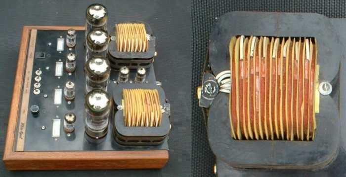
Figure 3 - Pi Windings For An Output Transformer
An alternative to the traditional layered winding is called a pi (π) winding. These have never been popular, perhaps because winding machines need to be specially set up to wind this way, and inter-layer insulation becomes a problem. A photo of a pi wound transformer and the amplifier with both visible is shown above. This was built by John Burnett some years ago. The final design had 8 primaries sandwiched between 9 secondaries. Pi wound transformers are symmetrically balanced and have a high frequency response that's twice that of a conventional layer wound output transformer. This type of winding will give the best resistance matching between each half of the primary.
Toroidal cores are an excellent way to make a high performance output transformer. Because of the toroid shape and the total absence of even the smallest air gap, leakage inductance is very small. Minimal interleaving will give results that are better than a traditional transformer with many interleaved windings. Toroidal cores are extremely sensitive to the smallest DC imbalance though, so it is imperative that the output valves are closely matched to ensure that any DC component is cancelled at all power levels. Each output valve must have a 10 ohm cathode resistor to facilitate current measurements, so it is easy to simply measure the voltage across the resistor to determine the current at various power levels from zero to maximum.
Regardless of the shape of the core, it is essential that there is enough core material (usually silicon steel, and preferably 'grain oriented') to support the maximum flux density allowable before core saturation effects become audible. This only affects the lowest frequencies, and is independent of inductance. A transformer might have more than enough inductance, but be unable to reproduce any frequency below 50Hz without serious distortion. The distortion is caused by core saturation, and the only ways to reduce the flux density are to either reduce the voltage, add more turns or use a larger core size.
A normal silicon steel alloy can be used up to a flux density of 1.7 Tesla for grain-oriented material, or about 1.3 Tesla for non-grain-oriented (ordinary) core material. For audio, the maximum recommended flux density is up to 0.5 Tesla - any greater, and distortion rises dramatically. In general, values between 0.3-0.4 Tesla are optimum for low distortion when using E-I laminations. Toroidal transformers can often be operated at higher flux density because magnetising losses (the cause of premature distortion) are very low. I have no intention of attempting to describe the design process, since it is the subject of entire books. There is some info on the Net that may be useful, and the ESP site has several articles dedicated to transformers - see the Transformers - Part 2 article for some of the details you need to understand transformers in general.
Many output transformers are far too small to allow full power at the lowest frequency claimed. While the response of a '100W' transformer might be flat to 20Hz at 1W or even 10W output, at 20Hz it may only be capable of 30W before distortion becomes intolerable. As frequency is reduced, you need more turns on the primary, and/or a larger core to keep the flux density well below saturation. As with all manufactured products, there is a careful balancing act, namely performance (and size) vs. cost. A transformer that can provide 100W at 20Hz with no audible distortion becomes very large indeed, or has so many turns on the primary that resistive (copper) losses are excessive and high frequency performance suffers.
As an example, if one were to use a standard 1½" (38mm) lamination with a 2" (50mm) stack, you ideally need over 2,500 turns of wire on the primary to be able to get down to 25Hz at full power, assuming 600V RMS across the primary (typical of an amp with a 500V plate supply). Considering that the total winding resistance needs to be low (preferably less than 100 ohms), the transformer will be difficult to wind, other than by someone who is very skilled. This is a large and expensive transformer - the core alone weighs about 3kg. According to the Radiotron Designer's Handbook, a rule of thumb figure is that the core should weigh about 77g/ W, so for 100W that comes to 7.7kg. Unfortunately, the figure given was not accompanied by details of the minimum frequency allowed, however it was mentioned that the core could be reduced where less extended bass or higher distortion could be tolerated. IMO, the figure is highly pessimistic, albeit of some interest value. In general, the core needs to be only about half of that claimed, provided it uses grain-oriented silicon steel. Bear in mind that full power down to 30Hz or less is never needed, because the energy levels below ~40Hz are generally quite low.
It is generally considered that inductance should be great enough that the inductive reactance at the lowest frequency is no less than the plate-plate impedance of the transformer (RP-P) in parallel with twice the plate impedance of the valves (2 × rP). At this frequency, the response will be 3dB down. To calculate the minimum inductance ...
Z = ( 2 × rP ) || RP-P (Where Z is total impedance in ohms) L = Z / 2π × f3 (Where L is inductance in Henrys, XL is inductive reactance in ohms)
In practice, inductance needs to be much greater than this, in large part just to keep the maximum flux density to the minimum. The inductance is at best a 'moving target', because it changes depending on the signal level and frequency. It is also a notoriously difficult figure to measure, because core losses and winding resistance generally make most measurements meaningless. It's not at all uncommon for a good output transformer to have a calculated inductance of well over 100 Henrys, even though less than half that may be 'sufficient' based on the formula. At the loudspeaker bass resonant frequency, the overall impedance can increase markedly, so the transformer usually needs a lot more inductance than simple theory might indicate.
Output transformers are certainly not magic, but the design of one that gives excellent performance over the entire frequency range is as much an art as it is a science. There are too many intangible factors, and too many conflicting requirements to be able to simply jot down a nice formula that covers everything.
Most of the old artists who used to know all the tricks and could design a great transformer on the fly have now passed on, and with their passing a great deal of valuable knowledge has been lost.
While the old books on the subject contain much of the info we need, I can assure you that it doesn't make for light reading, and most of the formulae use old Imperial measurements and units. Yes, they can be converted, but not by me.
Especially for low frequency operation, a net DC in the windings will cause premature saturation, loss of inductance and distortion. Centre tapped primaries have DC flowing, but in a properly set up amplifier, the DC in each half of the winding will be the same, but in opposite directions. This causes the flux caused by the DC to be completely cancelled, so the core at idle has no flux at all. Any DC that causes flux in the core simply creates problems, and the only way to prevent saturation is to include an air gap. This reduces the effective permeability of the core, so more turns are needed for the same inductance. The maximum AC level that the core can handle without saturation is less than half of the maximum. The transformer must be considerably larger and have more turns to get sufficient inductance for good low frequency performance (thus increasing winding resistance and leakage inductance), but it will never work well.
Needless to say that SET (single ended triode) amplifiers have the full DC quiescent current flowing in the primary, and are an unmitigated disaster in this respect.
The requirements for good high frequency response are almost diametrically opposed to those for low frequencies. This is why primaries and secondaries are interleaved, to try to make the transformer's bandwidth as wide as possible. Winding resistance, stray capacitance, leakage inductance and phase shift (aided and abetted by the loudspeaker) all increase the distortion at high frequencies, and even maintaining a perfectly balanced primary winding becomes difficult.
Above a few kHz, the transformer core is redundant - it can actually be physically removed, and the transformer still works fine. In fact, distortion will usually be lower because there are no core losses to mess things up. However, leakage inductance increases because there's no core to guide the magnetic flux. The leakage inductance is only one of several issues that cause premature high frequency rolloff though.
There are plenty of opportunities for a transformer to mess up the high frequency response. Inter-winding capacitance (primary to secondary), inter-layer capacitance (between primary layers), capacitance to the core, high frequency impedance imbalance caused by unbalanced stray capacitance, and of course the impedance of the loudspeaker load itself. It is obviously important that leakage inductance is the same for each half of the primary winding.
As noted above, leakage inductance is a major contributor to high frequency losses. Leakage inductance is a stray component in the equivalent circuit, and is caused by flux generated in the primary winding(s) that fails to pass through the secondary winding(s). Interleaving minimises the effect, but some flux always manages to 'escape', and the leakage inductance is in series with the main winding. As such, it creates an impedance that blocks high frequency signals, with the effect becoming worse as frequency increases. The impedance of leakage inductance at a given frequency can be determined from ...
XL = 2π × LL × f (Where XL is inductive reactance in ohms and LL is leakage inductance in Henrys)
If a transformer has a leakage inductance of 20mH, this has an impedance of 2,500 ohms at 20kHz. This appears in series with the main winding and the output valves' plate impedance , so if the transformer's primary impedance is 2,500 ohms, winding resistance is 100 ohms and plate resistance is 4,000 ohms (purely as an example), the output will be 3dB down at 52.5kHz as a result of the leakage inductance. As you can see, a relatively small amount of leakage inductance can easily cause a rather large loss of HF signal. A toroidal output transformer may have leakage inductance of less than 3mH, while a transformer with basic (and minimal) interleaving may exceed 30mH. Leakage inductance for a given transformer winding topology is proportional to the square of the number of turns.
Z = ZP-P + rP + RW (Where ZP-P is plate-plate impedance, rP is plate resistance and RW is winding resistance) f3 = Z / ( 2π × LL ) (Where f3 is the 3dB down frequency in Hz, Z is total impedance, and LL is leakage inductance)
For the above example, the high frequency response will be -3dB at a frequency of 52.5kHz. If a transformer has multiple interleaved secondary windings, and a number of speaker impedance taps, the leakage inductance will almost always be different (higher) whenever the complete secondary winding is not used. For example, if speaker taps are provided for 4, 8 and 16 ohms, the entire secondary winding cannot be used for all three taps. Windings can be in series for 16 ohms and in parallel for 4 ohms, but the 8 ohm tap cannot use the entire secondary. Even parallel connections must be made with great care, and each paralleled section must have exactly the same number of turns. One turn difference may cause serious losses, localised heating and very poor performance.
Finally, because the transformer has stray capacitance and leakage inductance, it also has a self-resonant frequency. Depending on the transformer, this may range from perhaps 50kHz or so, to several hundred kHz. Self-resonance causes ringing on sharp transients, and can be a source of voltage spikes if an amp is overdriven.
The application of negative feedback was done to achieve three primary goals ...
Simple (cheap) products were far more interested in the noise reduction than anything else, but were also limited by the output transformer, and could rarely apply enough feedback to make much of an impression on distortion or impedance, but the noise reduction was essential. Without feedback, noise levels from the speaker were often very intrusive, so feedback reduced the noise and gain to 'acceptable' levels.
Because a transformer has no intrinsic impedance, it simply reflects the impedance of the load back to the output valves. If the load impedance changes, so does the impedance seen by the valves. Loudspeaker loads are notorious for having an impedance that varies depending on the frequency, so the output valves do not have a constant impedance. Because of this, it is traditional that output transformers are designed based on the nominal load impedance, which is assumed to be resistive across the whole audio band.
There is actually no choice, because it would be impossible to try to account for the actual impedance of every loudspeaker at every frequency, so a compromise is essential. The following therefore assumes a resistive load at the nominal impedance for all calculations. Most of this information is described thoroughly in the first part of this article, and will only be covered briefly here.
The datasheets for many valves provide a recommended plate-plate impedance for various operating conditions, but these are academic rather than practical. They generally assume that there are no losses, and that the power supply voltage remains constant regardless of load. Neither of these conditions exist in a real amplifier.
The transformer turns ratio (and therefore its impedance ratio) is determined by the maximum voltage and current available from the output valves, without exceeding their ratings. Care must be taken to ensure that there is a safety margin, especially for the peak voltage. Valve base or transformer flash-over (where the peak voltage exceeds the capability of the insulation to prevent current flow) must be avoided, as it can lead to very expensive repairs.
The AC voltage appearing across the primary of a push-pull output stage is double the voltage at the plate of either output valve. All output valves have a 'saturation' voltage, and the plate will usually reach a minimum voltage of between 30V and 120V above the cathode voltage. The exact figure varies with valve type and age, screen voltage and load. While it is possible to obtain figures from datasheets, this area is often highly optimistic, leading to false conclusions. A 'rule of thumb' is that RMS voltage across the transformer is approximately 1.1 times the DC voltage.
For example, a push-pull amplifier may have a plate supply voltage of 600V. If we assume fixed bias and a minimum plate-cathode voltage of 80V, the peak voltage available on the plate is 600 - 80 = 520V. This is ~368V RMS. The total voltage across the primary is therefore 736V. This assumes that the DC supply voltage does not fall, but it will. Typical DC regulation is around 10%, so at full load, the supply voltage will be reduced by 10% of 600V, or 60V. The maximum AC on each valve is now 600 - 80 - 60 = 460V, or 325V RMS. This gives a total voltage across the transformer primary of 650V RMS. The shortcut method (multiply quiescent DC by 1.1) gives 660V RMS - that's close enough for me.
If this amplifier is intended to give 50W into 8 ohms, the voltage required on the secondary is 20V RMS, so the turns ratio is simply the primary voltage divided by the secondary voltage - 33:1. The impedance ratio is the square of 33, which is 1089:1, so the primary impedance is 8,712 ohms. Note that I have made no allowance for the valve type here. To a large extent, this is immaterial - one simply chooses valves that have the required ratings or amends the voltage and power to suit the valves you wish to use. For this example, EL34 or 6L6GC would be suitable, or you could just use KT88s and be done with it. Of course, to some extent at least, a decision has already been made for the output valves. No-one would be silly enough to assume that you could get 50W from a pair of EL84 valves for example.
If it desired to use negative feedback, there will be phase shift within the transformer and valve output section that will ultimately cause oscillation. While oscillation can occur at high or low frequencies, few valve amplifiers have sufficient gain at (say) 5Hz to oscillate, but most will have more than enough gain at high frequencies. At the frequency where the transformer's output is 3dB down, there is a phase shift that when added to other phase shifts throughout the amplifier section, may be sufficient to cause oscillation. One common method to correct the phase is to add a small capacitor across the feedback resistor to shift the phase back far enough to prevent oscillation, and in other cases the gain of the power amp section is deliberately rolled off to ensure the amp will be stable.
While it is possible to calculate the phase shifts and determine all component values mathematically, it's generally far easier (and a lot faster) to use an empirical approach. There are so many influences that can't easily be calculated or modelled that attempting to do so is a waste of time. If the transformer's self-resonant frequency is within the amplifier's bandwidth, it may be necessary to use a Zobel network to minimise phase shift which can easily exceed the critical 180° value required for oscillation. With that much phase shift, negative feedback becomes positive feedback, and the amplifier will oscillate if no corrective measures are taken.
Valve amplifier power supplies are usually fairly crude, but for many designs they should be far better than is usually provided. Especially for ultra-linear operation, the B+ supply should be well regulated and as hum-free as possible. In the heyday of valve amps, choke input filters were common in power supplies, but these are few and far between now. The traditional capacitor input filter is almost universal, even though this type has very poor regulation. Part of the problem is that high current chokes (inductors) are large and expensive, while high value, high voltage electrolytic capacitors are now common - largely due to the demands of switchmode power supplies. While valve aficionados might like to think that these electros are made for them and their valve amps, this is sadly not the case.
It seems that it's not at all uncommon for designers to specify transformers that do not have a high enough VA rating for valve amps. This is especially true of guitar amps, because they are often pushed into clipping for extended periods, so output power is far greater than with a sinewave. A typical 100W valve amp can deliver over 150W when pushed to its limits, and this must be accounted for in the design. All valve amps have a fairly high quiescent current, being the output stage bias current, the current drawn by the preamp stages (which is usually very small), and of course the heaters for all the valves. There is no possible guideline for this - it depends on a great many factors and must be calculated for each design - with allowances!
There are many different voltages needed in a typical valve amp, and it is imperative that any disturbance caused by the output stage cannot get through to the preamp stages. A form of oscillation commonly referred to as 'motor-boating' is the result, so called because it sounds rather like an old style single cylinder boat engine. If this type of oscillation is experienced, it's almost always because there is insufficient filtering between the stages, or the preamp is being allowed to provide amplification for exceptionally low frequencies.
It must be understood that early designs often used very small filter capacitors. This wasn't done to improve the sound, it was because high value electros simply weren't available. If you look inside a 1940s era amp, you might see caps rated at 8µF or perhaps 16µF or 20µF+20µF (in a single can), where you might otherwise have used a 450µF cap. The values used were what was available at the time, and back then no-one would even think of using a 470µF 450V cap, because they didn't exist for consumer products (and perhaps not at all). Some amplifiers even used paper and foil in oil caps. While these have an (allegedly) indefinite life, available values were extremely low by today's standards.
The current trend to try to make amps just as they were in the 1930s, including old style low-value electrolytic (or paper in oil) caps is just plain silly. Anyone who thinks this is a good idea must - immediately - have their music collection transferred to shellac discs to experience the full benefit of the era. It's also best that quartz clocks in the listening room be replaced by mechanical clocks. Pipes and smoking jackets are optional.
Power transformers often require several different windings, some with high voltage insulation so the rectifier valves filaments are isolated from everything else. The filaments of most rectifier valves are directly heated, and the cathode is the positive voltage (more on this later). Every extra winding takes up valuable space in the transformer, so it is in everyone's best interests to keep the number of windings to a minimum. In the early days (valve rectifiers), the high voltage secondary was always a centre-tapped winding. This made rectification easier, but wasted quite a bit of space and ensured that a much greater voltage than necessary was developed. A centre tapped winding for a full wave rectifier needs a total voltage that's double that of a bridge rectifier, but there was no other sensible choice at the time. While voltage doublers and even triplers were made using valve rectifiers, in most cases multiple insulated filament windings are needed - somewhat inconvenient to put it mildly.
Figure 4 shows the basic rectifier types that are seen in valve amps. For the simulations, the transformer was assumed to be ideal (ie. lossless, other than the equivalent winding resistance as shown), and the load on each 600V supply was 6k (nominally 100mA). Diodes are all 1N4007.
Note that higher voltage diodes are required for the full wave rectifier. Maximum reverse voltage across the diodes is double the DC output (1,200V in this case). The other rectifiers only require the diodes to be rated for the maximum DC voltage.
Figure 4A - Rectifier Types, Full-Wave & Bridge
The traditional full wave rectifier is only sensible when a valve rectifier is used, which in itself is a silly thing to do because of the additional losses incurred. While the bridge rectifier is a better proposition, it will (like the full-wave rectifier) commonly require two filter caps in series to get the required voltage rating. In the two circuits above, balancing resistors are included across the filter caps to ensure they both get the same voltage. These are not strictly necessary because (contrary to popular belief) they will balance themselves, but it's traditional to include them anyway. They also serve a secondary purpose - discharging the filter caps. This prevents high voltages from remaining across the caps after the power is turned off.
Figure 4B - Rectifier Types, Centre-Tapped Bridge & Voltage Doubler
The centre-tapped bridge is a very common arrangement, and no balancing resistors are needed. It provides a half voltage point, and ripple frequency is double the mains frequency on both full and half voltage points. The voltage doubler produces ripple at the mains frequency on the half voltage point.
The 4 types shown all provide almost identical ripple voltage, and the output voltages, input currents and efficiencies are shown in the following table. The winding resistance is based on a rough guess, and is shown as an indicative figure only. The voltage doubler supply needs half the turns, so wire cross-sectional area should be doubled, making resistance one quarter of that for the other types. Frequency used for the simulation was 50Hz, and DC output current is about 94mA for each version.
| Type | RMS Current | Peak Current | Ripple | DC Out | VA Input | Power Out |
| Full Wave | 2 × 158mA | 642mA | 2.27V RMS | 565V | 94.9 VA | 53.27 W |
| Bridge | 223mA | 657mA | 2.27V RMS | 564V | 94.4 VA | 53.12 W |
| C.T. Bridge | 2 × 223mA | 636mA | 2.27V RMS | 565V | 95.5 VA | 53.12W |
| Doubler | 445mA | 1.27A | 2.26V RMS | 563V | 94.6 VA | 52.99W |
The RMS current is comparatively unimportant - the peak current combined with winding resistance is the major cause of poor regulation for all capacitor input filters. The average power dissipated in the winding resistance is (virtually) identical for each of the rectifiers (~2.5W), and so is their overall efficiency. The traditional full-wave rectifier is the worst choice possible, because only half the winding is used at any one time, so often requires a larger transformer for the same output to accommodate the extra wire. The peak current is much the same as that for a bridge rectifier, but twice as much valuable winding space is occupied by the winding compared to a bridge (centre-tapped or not) or voltage doubler.
Note that both the RMS and peak input currents (in the transformer secondary) are dramatically higher than expected. All capacitor input filters have the same characteristic. If input power is measured, all rectifier types are about the same - about 56W give or take ½W or so. The VA ratings are important to ensure that the transformers are properly sized, regardless of rectifier type. The apparently high VA rating is caused by the non-sinusoidal current waveform - all transformers/rectifiers shown have a power factor of about 0.59, and this is quite normal for capacitor input filters.
| All results shown here were simulated, and used a pure sinewave. In reality the mains waveform is generally distorted (typically flat-topped) to some extent, so measured values will differ slightly from those shown. In particular, peak currents will be slightly lower than the simulation would indicate, and voltages will be a little lower even for the same RMS transformer voltages and winding resistances. VA ratings were measured (again using the simulator) in the primary circuit of the transformer. If you were to add the secondary currents for the full wave rectifier for example, you get a completely wrong answer (2 × 158mA is 316mA, but this is incorrect). The figures as shown are believed to be accurate, within the limitations of the simulator I use. |
Both the voltage doubler and centre-tapped bridge need two capacitors, and their voltage rating is half that of the other two rectifiers, but capacitance is doubled. You also get a 'free' half voltage supply, but the ripple voltage is at the mains frequency for the doubler (50/60Hz), not 100/120Hz as seen on the 600V rails. Above 450V, most rectifier/filter combinations will need two caps in series, because higher cap voltages are not readily available. In general, when making a decision about the type of rectifier to use, the bridge (or centre-tapped bridge) is usually the best choice. If you only require a capacitor input filter like those shown above, the voltage doubler may win on cost - if you can get the proper transformer.
Voltage doublers have a poor reputation with many electronics designers, but that's often due to unrealistic comparisons, for example using the same transformer (so winding resistance is not changed) or having unrealistic expectations. From the above, it is obvious that all power input and output figures are very close, so there is no inherent inefficiency (a common claim, but false as you can see from the table).
Absolutely the worst possible choice for a rectifier is the full wave. The transformer is inefficient and may require a larger core because twice as much wire is needed, yet only half the winding is used at any instant in time. Diodes need a much higher voltage rating because the peak inverse voltage is double the DC supply (analyse the circuit closely if you can't see the reason for this). The AC voltage output is also far higher than for a bridge or doubler, so transformer (and external) insulation must be appropriate for the voltage. If it can possibly be avoided, never use the standard full wave rectifier - use either of the bridge circuits, or voltage doubler.
For reasons that I cannot comprehend, there are some who claim that the 'soft' (soggy is more descriptive) supply that was used by XYZ company in 1950 is 'good' and makes an amp sound 'better'. Bollocks! In the case of hi-fi amps, you need the supply to be as stiff as possible. Any change in the B+ voltage causes the valve bias current to change too, so at high levels the amp will be under-biased. In the case of push-pull tetrode or pentode amps, it is sufficient to regulate the screen voltage and this will maintain stable bias. Once the screen voltage is regulated, the negative bias supply should also be regulated. Failure to do so may cause bias shift as the mains voltage changes.
For ultra-linear output stages, the full B+ should be as stable as possible. Only a very few manufacturers used a separate output transformer winding for the screen so it could be operated at a lower voltage. For home construction or even modern manufacture, it's not viable because of the considerable extra cost of the transformer. Where the separate winding was used, the screen supply was sometimes fully regulated (McIntosh MC3500 & MI350 for example). There is nothing to be gained by having a soggy power supply that collapses as soon as you demand some power from the amplifier.
The ideal power supply has low ripple, and can provide the full rated voltage right up to full power, without significant collapse or increase in ripple. Choke input filters were one method that was used to achieve this, but in a new design it's almost certainly cheaper to build a regulated supply. This is not a trivial undertaking, because the regulator has to be capable of surviving catastrophic valve failure. While valves were being made in the US, UK, Europe and Australia, catastrophic valve failure was almost unheard of for hi-fi amps, so no special precautions were needed. This is no longer the case.
The situation is different for guitar amps. A soggy power supply allows transients to reach full power, but the continuous power is reduced. Whether this actually does anything useful is debatable, although many players insist they prefer the sound of amps with valve rectifiers (which provide a soggy supply as a matter of course). Whether they would be able to pick the difference in a double-blind test is debatable, because the power difference is usually considerably less than 3dB.
Where it is determined that this is not only audible but provides the desired sound, it's easily achieved by using resistors in series with silicon rectifiers. As noted elsewhere in this article, valve rectifiers are something to be avoided at all costs. They are expensive, inefficient, don't work very well, have often poor life expectancy and have no redeeming features.
Valve rectifiers do provide one small benefit, in that the HT supply gets an automatic soft-start as the heaters or filaments take time to reach operating temperature. This may be an advantage in some circuits, but if a delay is needed it's far better to do it electronically (using a MOSFET for example) than to use a vacuum tube rectifier with its many faults and limitations.
Normally, one can say that DC has no sound, because it's DC and you can't hear it. With valve amps, this is not the case though. For a transistor or opamp preamp, the supplies are rectified, smoothed and regulated, so there will be virtually no ripple and a minimum of noise. These options are too expensive and far too irksome to implement with high voltages.
Small regulators are sometimes used to maintain very low ripple and good voltage stability for screen grids, but even this is uncommon. Most valve amps operate with unregulated power supplies that often have far too much ripple - especially at full power. Since the DC has a considerable amount of AC ripple at either 100Hz or 120Hz (50/60Hz mains respectively), it now has a very definite sound - none of it desirable. The ideal power supply maintains constant voltage, with the smallest amount of AC ripple possible.
In the early days of valve amps, capacitance was extremely limited, so high ripple was common. Today, we can get much higher capacitance - this allows ripple to be minimised, but it is virtually impossible to remove it completely. In all valve amps, it is necessary to use as much capacitance as you can. While you will see many amps with filter capacitors of 50µF or less, you should be aiming for 500µF or more in most cases. The smoother DC supply will always improve sound quality, but naturally there is a point where adding more capacitance no longer provides a proportionate improvement. This is the point where the 'law of diminishing returns' comes into play.
Just adding more caps is rarely the whole answer of course. Filter chokes play a big part in ripple reduction, and where current is relatively low resistors are used to achieve both ripple and voltage reduction. This is commonly seen in preamp sections. Capacitors must be large enough to ensure that no low frequency supply variations affect the preamp supply. If too small, the ripple might be inaudible, but the whole amplifier may have low frequency instability. This is commonly known as 'motor-boating', as noted above.
Power supply design is critical to the success or failure of any valve amplifier project. Every aspect of the supply requires meticulous attention, and minimisation of series resistance for high current supplies is a high priority to ensure good regulation. The DC voltage will fall as current is increased - there's no getting around that other than adding expensive regulator circuits. The best valve power amps ever made didn't use regulated B+ supplies though, so we know that excellent performance is possible without being silly.
Where tetrodes or pentodes are used, consider regulating the screen supply. Current is relatively low if designed properly, and the screen grid is critical to the operation of the valves - far more so than most amateur designers realise. If you are trying to make a high quality amp, resist any temptation to duplicate the techniques you see in guitar amps. Almost invariably, they are designed for lowest cost manufacture, and generate excessive distortion while simultaneously abusing the valves.
The theoretical goals of a power supply are almost achievable (perfect regulation and zero noise), but only at a cost that is prohibitive. As McIntosh, Quad, Dyanaco, Audio Research and many other have proven, extraordinarily good amplifiers can be built using traditional power supply techniques. You cannot afford to be shy when it comes to capacitance and inductance - these two can reduce DC ripple and noise to manageable levels, but your greatest friends are large electrolytic capacitors.
A rough guide is that for a nominal 500V supply, I suggest that you need about 2µF of storage and smoothing per Watt of average DC output power for amps with 50W or more output. Note that this is maximum DC power from the supply, not output power into the speaker. For a capacitor input filter, this will result in a peak to peak ripple voltage that's about 1.5% of the supply voltage. This capacitance may be distributed - with half before a filter choke and the remainder following the choke. There are many dependencies here, so hard and fast rules cannot be applied - this is simply a starting point.
For lower powers it's advisable to add more - clearly a 5W supply (usable for perhaps a 1.5W amplifier) with only 10µF of smoothing is barely adequate, although the ripple percentage does remain fairly consistent. To reduce ripple, the following circuits are common.
Having dispensed with full wave rectifiers in section 5, the only sensible choice for a choke input filter is the standard bridge rectifier. Voltage doublers cannot be used, because they are - by nature - capacitor input filters. A choke (inductor) input filter has two major advantages - voltage regulation and ripple voltage. Because of the inductor in series with the filter cap, the large current peaks that we get with a capacitor input filter are gone, so there is less instantaneous voltage drop across the winding resistance. Ripple is also much lower for the same capacitance, but DC voltage is lower. The DC voltage for a capacitor input filter is roughly the RMS voltage multiplied by 1.414 (√2), but an optimised choke input filter has a DC output that's only 0.88-0.9 of the applied RMS voltage. The theoretical formula is ...
Vout = ( 2 × √2 / π ) × VRMS Almost exactly 0.9 × RMS voltage
If 500V AC goes in, you'll get about 450V out if all winding resistances are zero. Once the winding resistance of the choke or the power transformer are included, these will both reduce the DC voltage and the regulation.
Doubling the load on a capacitor input filter supply almost doubles the ripple, but with a choke input filter there is virtually no change - the ripple voltage remains almost the same. In addition, the harmonic content of the ripple is much lower - the sixth harmonic (600Hz) may be 75dB below the 100Hz level. Compare this to a capacitor input filter, where the sixth harmonic is only 37dB below the 100Hz level. This really matters for any amp that has poor power supply rejection.
Somewhat surprisingly, with a large inductance choke input filter, the transformer secondary AC current is almost a squarewave at the mains frequency. Meanwhile, current through the choke is almost DC, because the inductance opposes any change of current. The RMS value of the AC current is the same as the DC current, so the current peaks we saw with the capacitor input filter are gone. With all these nice positive things to say about choke input filters, you may well be wondering about the downsides, and they come in bucket loads.
When power is first applied to any choke input filter, there is a 'ringing' period, where the voltage climbs to a peak, drops below the final voltage, and gradually settles down to a steady voltage. The period is determined by the resonant frequency of the inductor and following capacitor, and the maximum amplitude of the ringing is determined by the load. Choke input filters also require a minimum load, or the voltage will simply rise to the peak of the AC waveform. This can represent a significant over-voltage for capacitors, and is one of the reasons that many manufacturers include a surge voltage rating. This used to be more common than it is today, but is an important consideration.
Before the valves have warmed up and start drawing current, the voltage will rise to the maximum, only settling back when sufficient current is drawn. The minimum current depends on the size of the choke itself - higher inductance allows for lighter loads (less current). For the circuit shown below, the minimum inductance for a 100mA load is 4 Henrys (winding resistance is 50 ohms). Anything less than this allows the DC voltage to rise above the nominal 370V expected from the supply.
Figure 5 - Choke Input Filter
As the load current is increased, the inductance may be reduced with little change in performance. Since the choke is iron cored, has considerable DC in the winding, and must have an air-gap to prevent saturation, a new possibility emerges. Almost by its very nature, an inductor built as described will have a variable inductance. As current increases, inductance decreases and vice versa. This is known as a swinging choke. Using a swinging choke allows the choke to be physically much smaller than would otherwise be the case. Swinging chokes are made with a (much) smaller air gap than a fixed choke, so the inductance varies with load as the core starts to saturate. They don't work as well as fixed chokes, but are smaller, lighter and cheaper.
A fixed choke can be positively massive if it must handle significant DC yet retain its full inductance - in exactly the same way as a transformer for a single-ended amplifier must be much larger than expected. A large air gap is needed to maintain core flux density below saturation at all currents. Winding resistance (and resistive losses) will be greater than for a swinging choke.
Figure 6 - Power On Performance With Different Inductances
Figure 6 shows the behaviour of a choke input filter when power is first applied. If the inductance is correct for the load at power-on, you'll get the performance shown by the red trace. The green trace shows what happens if the inductance is too big - in this case, increased from 4H to 10H. As with transformers, I am not about to try to provide a tutorial that will allow you to design filter chokes, and I'm not even going to attempt the descriptions of how to design a choke input filter. There are so many complications and possibilities that any attempt would be futile - and that's assuming that, a) anyone is really interested and, b) that you can actually get a filter choke that's designed for what you need. It is very common that Class-AB amplifiers using choke input filters require a bleeder resistor to maintain the minimum load to ensure that the voltage cannot rise above the design voltage - these will naturally waste considerable power and get rather hot!
Perhaps surprisingly, choke input filters are the only circuits that benefit from valve rectifiers. Because the valve heaters or filaments heat slowly, this prevents the voltage surge seen in Figure 6. Of course, this can be replicated with a soft-start circuit, but that does increase overall complexity. Choke input filters are uncommon in modern equipment.
There is a rough formula that can be used, and it generally works well enough for a fixed choke ...
L = RL / 940 For a 50Hz supply frequency, and where RL is the effective load resistance L = RL / 1130 For 60Hz mains
Using the above, the inductance needed for a 3,600 ohm load is 3.8H for 50Hz (100Hz ripple), or 3.2H for 60Hz (120Hz ripple). This corresponds very well with the simulated version, and although highly simplified will serve you well if you wish to pursue this option. The power factor of a transformer connected to a choke input filter is roughly 0.65 if the choke is sized properly. Good regulation is one of the claims always made about choke input filters, but this can only apply if the winding resistance of the choke and transformer are low. A high winding resistance will degrade regulation because of the resistive losses - it's no different from adding a series resistor to an ideal inductor.
Figure 6A - Ripple Voltage vs. Filter Type
For comparison, the above shows the ripple voltage (both amplitude and waveshape) for a choke input filter (red) and capacitor input filter (green). Both supplies used the same capacitance and load resistance. The capacitor input filter shows sharp transitions, indicating significant harmonic content, while the choke input waveform is more like a sinewave (although it's not a very good one). The snapshot of the waveforms was not taken until all voltages had settled to steady state conditions.
Figure 6B - Capacitor Input Filter Spectrum
The spectrum of harmonics from the capacitor input filter shows that there is energy out to 5kHz and beyond. This is the reason that you often don't hear hum when there's ripple voltage breakthrough into the signal - it's more of a buzz, with a hard edge to the sound.

Figure 6C - Choke Input Filter Spectrum
By comparison, the harmonics for the choke input filter waveform are much less intrusive, and there is no harmonic above 10µV beyond 1.5kHz. Note that for both filter types, the harmonics are both even and odd, so from a 100Hz input from the rectifier, you get harmonics at 200Hz, 300Hz, 400Hz, 500Hz, etc.
In switchmode power supply terminology, a choke input filter operates in continuous mode. This means that there is always current in the choke, and always flowing in the same direction. With the minimum inductance (based on the formula above), the current falls to zero only very briefly - less than 1ms. If inductance is made a little greater, current will never fall below zero.
For most amplifiers, a capacitor input filter is the most common, and this is often followed by an inductor and second capacitor. This forms a pi (π) filter - so-called because it resembles the Greek letter π. In most cases, the inductance is relatively low, because to make it larger would add 'needless' expense to the product. As with the choke input filter, the filter choke in a pi filter has a large DC component, so the core must be gapped to prevent saturation. A typical inductance might be 1H or so, but this can provide significant smoothing. Chokes used in pi filters can also be swinging types if there is significant current variation in operation.
Figure 7 - Pi Filter With 1 Henry Inductor
With the capacitor input filter, the ripple voltage was 2.27V RMS, and even adding another 100µF cap only reduces that to 1.14V RMS. However, a pi filter with a 1H choke and a second 100µF cap reduces ripple to about 54mV - a very worthwhile improvement. Output voltage is reduced by only 5V DC with the load shown. This is undoubtedly the most common arrangement for valve amplifiers, and it allows the plates to receive the basic 'raw' DC, but screen grids and remaining circuitry are isolated and have additional filtering due to the filter choke.
These are an unmitigated disaster. There is absolutely no good reason to use valve rectifiers for anything. Because of their construction and the way they are designed, they are always used in the full wave configuration. As noted above, this makes for an extremely inefficient winding window utilisation for the transformer because the winding is twice as big as it should be. Add to that the fact that valve rectifiers are dreadfully inefficient themselves - they have a significant plate resistance and this is in series with the DC supply.
Regulation is far worse than if silicon diodes are used, simply because of the voltage drop across the rectifier valves. In addition, the maximum value of the first capacitor is usually quite limited. In some cases it might be as low as 16µF, depending on voltage and winding resistance. The reason that the capacitance is limited is to prevent excessive startup current that will damage the rectifier. This is especially damaging if the AC input is turned on while the heater (or filament) is hot - only the valve and winding resistances act as current limiters, and peak current will be well above the recommended maximum for the rectifier valve. Valve rectifier datasheets usually give a maximum value for the capacitance that is allowable. For example, the 5AR4 has a maximum capacitive load of 60µF, and that's too small to get a low ripple supply for a high power amp (>30W output).
Figure 8 - Valve Rectifier, Capacitor Input Filter
Apart from the fundamental inefficiency of the rectifier itself, it also requires a filament supply that is elevated to the full DC potential. The filament requires considerable power, and this power is completely wasted. If we examine one of the higher current rectifier valves, we can see what happens. The 5AR4 is one of the 'better' rectifier valves, in that it has a low voltage drop and reasonably high current (up to 250mA). 9.5W is wasted in the heater (the 5AR4 uses an indirectly heated cathode, but it's directly connected to the heater), and at rated current the voltage drop across the valve is 'only' 17V. Plate resistance is typically 200 ohms per plate. Peak continuous plate current is 825mA, and peak non-repetitive plate current is 3.7A. Approximately 5W is lost in the valve itself with a load of 85mA - an overall loss of 14.5W. Because of peak current limitations, most valve rectifiers cannot drive sufficient capacitance to meet the 2µF/ W DC output power suggestion above, so excess ripple is common.
Compare this with a silicon diode. The 1N4007 (1,000V) has a maximum average current of 1A, the voltage drop at full current is about 1.1V and internal resistance is negligible. Peak (non-repetitive) surge current is 30A. Total power loss is less than 0.3W per diode. Now, some people like the effect of a 'soggy' power supply that collapses under load, especially with guitar amps. No problem, just add a couple of 5W wire wound resistors in series with the silicon diodes. You waste some power, but at least you don't need to worry about a filament or heater. If you want a big reserve, 1N5407 diodes will do nicely, 3A at 1,000V will satisfy all but the very highest power needs. Remember that if you use a full-wave (centre-tapped winding) rectifier, the diodes must be rated for at least double the DC voltage, and it will be necessary to use higher voltage diodes (or two in series) if the B+ supply is over 450V DC.
Because of the extra losses (in the above case 14.5W), the transformer needs to be larger. Where a 100VA transformer might have been suitable for an amplifier, it now needs to be 120VA to supply the losses in the valve rectifier. It's very difficult to imagine that this conveys any advantage - all it does is cost more, and throws more heat into the room. Even though I grew up with valve equipment, I have never liked valve rectifiers. They were a bad idea even when there was no substitute, but now that alternatives exist there's (almost) no reason to continue to use valve diodes at all.
There's a lot of disinformation around about rectifier 'sound'. In a properly designed power supply, the DC has no sound - it's DC. Regulation (or lack thereof) and ripple both can and do affect the sound. If you happen to like the sound of a collapsing power supply (for example), that's easily accommodated by adding some series resistance. Claims of inaudible switching transients somehow magically capable of affecting the music, but without being heard by themselves also abound. All such claims can be refuted easily in a blind A-B test, but as you have no doubt discovered, those who can hear these artefacts will never lower themselves to perform supervised blind testing so that others may be convinced. Faith has no place in electronics design. For some more into and some basic guidelines, see Section 5.1 above.
However, as noted above for choke input filters, valve rectifiers do have an advantage, because they are inherently slow, so the voltage surge common to choke input filters is reduced or even eliminated. Since this type of filter is so uncommon now, this single 'benefit' is pretty much eliminated.
Interestingly, the negative bias supplies almost invariably use silicon diodes, and this voltage is connected directly into the signal path. I've not heard anyone complain that the silicon diode 'ruins' the sound, yet if it were possible somehow, the bias supply has the capacity to do so. Many negative bias supplies are only half-wave, so should be easily audible (assuming that any DC supply is audible of course).
As noted earlier, valve rectifiers do provide a small benefit - the HT supply gets an automatic soft-start as the heaters or filaments take time to reach operating temperature. This may be an advantage in some circuits. If a delay is needed to allow the output valves to reach operating temperature before the HT is applied, do it electronically using a MOSFET, rather than using a vacuum tube rectifier with its many faults and limitations.
For amplifiers that use fixed negative bias (as opposed to cathode bias), the negative supply is the most important part of the entire power supply. While it would be nice if manufacturers would include a little detector circuit that prevents the main supply from coming on if the bias is missing (or not the correct voltage), I've only seen a couple of references to doing so, and those were from individuals rather than manufacturers. Many bias supplies are fed from a high impedance - either a resistor or capacitor from the main B+ winding. These supplies have the disadvantage that the bias voltage is usually slow to reach the correct value because of the high impedance feed.
A far better proposition is to use a separate winding on the transformer. Although current is extremely low, using hair-fine wire is a bad idea because it's too delicate. It doesn't require a vast number of turns for most amplifiers, so the space occupied is minimal. Reliability is very important - any failure can cause major damage to output valves and/or the transformers (both mains and output). All components must be of the highest grade to ensure long life.
The bias supply will usually be adjustable, and that means a pot or trimpot to vary the voltage divider. The negative bias should never simply be taken from the pot's wiper, as it's not at all uncommon for the wiper to go open-circuit after years of use (or storage). The drawings below are all fail-safe, so if the pot wiper disconnects, the bias voltage increases (goes more negative). If this isn't the way your amplifier is wired, then it should be changed.
Figure 9 - Typical Negative Bias Supply
Figure 9 shows one common arrangement, along with the remainder of the power supply (this is the same schematic shown as Figure 13 in the Analysis article). The fundamental lack of understanding of design principles is quite obvious - the full wave rectifier and resistor feed to the -ve bias supply being just plain stupid. The resistor feed ensures that the bias voltage is very s.l.o.w to reach the proper voltage (almost 4 seconds), yet it collapses very quickly when power is removed. A momentary power outage for any reason subjects the output valves to full DC voltage with almost no -ve bias voltage! While the valves will take this abuse (for a while, hopefully), in some amps (notably Marshall guitar amps) the HT fuse blows which puts the amp out of action.
The resistor feed is absolutely the worst method to obtain the bias supply, because it has such high impedance. Even a small amount of capacitor leakage (caused by heat for example) will reduce the voltage, and high value resistors have an annoying habit of eventually drifting high or going open circuit with age and relatively high voltage. A capacitor fed system can work better, but is still high impedance. Since a separate winding would add virtually nothing to the cost of the transformer (especially if the main HT winding were converted to use a bridge rectifier!), I am at a loss as to why it's not done as a matter of course. Everything becomes easy after that small winding is added.
Figure 9A - Typical Negative Bias Supply (Tapped Transformer Winding)
The method shown above is better than a resistor or capacitor bias supply, and is used in some amp circuits. Unfortunately, it's not possible to use a bridge rectifier because the winding is common with the main HT winding (it's just a tap). While (IMO) a half-wave rectifier is sub-optimal, it works well provided there's enough capacitance. With the values shown, ripple will be less than 1mV, and the hold-up time is long enough to prevent a possible output valve melt-down if there's a brief power interruption.
Where (for whatever reason) a separate winding is not available, a capacitor divider is far better than a resistor. Caps don't get hot because they don't dissipate any power, but it is essential that they are AC mains rated (X2-Class for example) or they will fail. The arrangement shown below has not been used to my knowledge, but is far better than the traditional capacitive divider. Being full-wave, the voltage builds to the maximum fairly quickly (full voltage in about 2 seconds), but the voltage still collapses faster than is desirable because a large storage cap can't be used. The standard method of using caps in this role is to use one cap, resistor and diode, but adding the second set costs very little to do, and gives a better bias supply.
Figure 10 - Improved (But Still Flawed) Negative Bias Supply
The source impedance of this circuit is low, but is still much higher than a transformer winding, so the filter capacitors discharge quickly. It can provide -40V with less than 5mV ripple - a little less than the version shown in Figure 9. Discharge after power is removed is just as fast as the Figure 9 circuit though. Capacitive dividers themselves are not uncommon, and have been used for years. Most use caps that are far too small, and this limits the minimum impedance of the bias supply (which must be as low as possible). There is considerable flexibility with a circuit such as that shown in Figure 10, but I would still much rather use a separate winding. The two 220nF caps need to be rated for 275V AC (X2-Class), although the voltage across them is only 205V RMS as shown with a 424V AC winding - remember, reliability is extremely important.
Figure 11 - Correct Way To Build A Negative Bias Supply
Wherever possible, negative bias should be taken from a separate winding. This enables all circuit impedances to be minimised. Remember that the output valve datasheets include a maximum total resistance back to the negative supply. This includes the grid resistor itself, as well as the DC resistance of the bias circuit. If two valves are used in parallel, the value must be halved. The DC resistance of the bias circuit has to be as low as possible, but cannot be regulated. A regulated bias cannot compensate for shift of the high voltage supply caused by mains voltage variations.
The above circuit has less than 1.5mV RMS ripple, and bias voltage reaches -40V in less than 0.5 second. The voltage naturally collapses when power is removed, but it takes over 1.5 seconds before it's fallen back to -20V after being turned off. A reasonable amount of bias voltage will remain available as the main power supply collapses, and if the amp is turned on again after a few seconds, no harm will be done. The worst case resistance increase from each output valve's grid resistor to -ve supply is less than 3k at any pot setting. The effects of grid leakage current are therefore minimised. It is essential that the RMS voltage of the bias winding is no more than the expected normal bias voltage. I've only seen examples of large filter caps and low impedances used in bias circuits in expensive hi-fi amplifiers, but they should be standard in all cases, because there is no other way to get a low resistance back to chassis earth. Even bridge rectifiers are uncommon, although they have been used (again, in expensive hi-fi amps). Because the circuit is driven from its own winding, the capacitance can be increased, and 100μF should be considered the minimum.
The supply shown gives a bias voltage variable from -45V to -37, and resistor values (and/ or the transformer winding) need to be changed to suit the output valves being used. The four things to be aware of are ...
This will always be a compromise, but it's much less so with a bridge rectifier and plenty of capacitance. This is the worst possible part of the circuitry to try to make cost savings. Where there's no separate transformer winding available, the Fig. 10 circuit is a reasonable alternative. The capacitance from the HT winding can be varied, depending on the overall impedance of the bias divider circuit. Note that the capacitors must be rated for the AC voltage available, and it may be necessary to use two in series to get the voltage rating. Do not use DC rated caps, as they will fail due to corona breakdown, which breaks down the dielectric. That will kill the capacitor, but it takes time so you can be left with a false sense of security.
High impedance bias supplies have a major problem that may not be obvious when everything is working as it should. If an output valve develops a fault (such as an internal short, or severe leakage to the grid), the current that flows through the output valve's grid resistor is limited only by the resistance and the applied voltage. If the resistor is 100k (a sensible value) and the fault voltage is 500V, you get plenty of current through the grid resistor. If the bias supply's effective resistance is (say) 47k and there's a plate to grid short, the current will attempt to convert a -42V supply to +131V, although in reality it will be a lot less because the electrolytic caps are reverse biased and will have significant leakage. We do know that a positive grid voltage of at least a few volts will be promptly applied to the grid(s) of the other valve(s) in the output stage. If the output resistance of the bias supply is reduced to 5k (as shown above), the bias is still affected - it will go from -42 to around -35V, not ideal for the output valves, but a lot better than somewhere between zero and perhaps +10V or so. A low resistance -ve bias supply is essential for long-term reliability. Even bias filter capacitor leakage becomes almost a non-event, because enough current is available to hold the voltage where it should be.
A low resistance negative supply with an acceptable hold-up time can only be accommodated with a separate winding. Even a small transformer wired 'backwards' with perhaps a 24V secondary connected to the 6.3V heater supply (12V for a 120V transformer) will work a lot better than resistive or capacitive dividers. This will give around 60V RMS to feed the bias supply.
You might want to include a bias-sensing circuit that will disconnect the HT supply if the bias voltage is below the minimum acceptable value. This requires some 'special' circuitry, because a standard relay cannot break the high voltage (AC or DC). This may become a project at some point (but no promises).
The 1H choke in the 600V supply reduces ripple from over 1.8V RMS on the first cap to less than 50mV RMS, at a current of about 85mA. Nothing to do with negative bias, but I thought I'd mention it anyway.
For many amps, hum from the heater wiring can become intrusive (even for the output valves), especially if the amp is used with high-efficiency loudspeaker drivers. The type of power supply depends on many factors, not the least of which is the current needed by the heaters. In most cases, it's simpler to use a regulated supply as this minimises the ripple, and maintains the design voltage across the heaters. The supply can usually be 12.6V, with output and preamp valve heaters in series, as this reduces the current. A regulator can also provide an automatic soft-start, because it will have inbuilt current limiting.
Where the heater current becomes significant (such as a large stereo power amp with perhaps 4 × KT88s for each channel), a commercial switchmode supply may be a good alternative, but it must be able to start under very high load. These usually have enough adjustment to allow the output to be set to 12.6V. Alternatively, a switching regulator running from a ~20V DC supply can be used. These have high efficiency, so heatsink requirements are minimal. It is also possible to use a choke input filter, but the choke will probably cost more than a complete switching regulator. DC heaters for output valves are not common because it rarely causes a problem. High efficiency compression drivers may make mains harmonics audible in some cases. Linear regulators are only suitable for low current DC supplies, but are the most economical choice for preamps.
Figure 12 - Simple DC Supply For Preamp Valve Heaters
The above shows a nice simple supply that can be used for three or four 12AU7, 12AX7 (etc.) preamp valves. These draw about 150mA each from 12.6V supplies. The diode in series with the common lead of the 7812 regulator raises the voltage to very close to 12.6V. The in-built current limiting means that there is almost no heater surge current, so the valves just warm up gently. The filter capacitor needs to be large enough to ensure that the regulator has sufficient voltage to maintain regulation at all times. If it's too small, some ripple will appear on the DC output and may become audible. The second small cap is to ensure that the regulator doesn't oscillate.
Because of the vast number of configurations that might be used, I don't propose to supply any further details. There are already several power supply designs on the ESP website that can easily be adapted for 12.6V output, as well as many other schemes on the Net. Choose wisely, and if the author claims that 12V is 'good enough' for 12.6V heaters, I suggest that you look elsewhere. All valves should be operated with the heater voltage as close as possible to the design value. Within 10% is 'good enough', but a regulator can give the exact voltage, so why not do so?
The purpose of this article (along with Part 1) is to show the options available to the valve amplifier builder, and the issues that may be faced in a practical system. While it often seems that many of the points covered are unimportant, they are the very areas where others have thought they were trivial, only to discover later than they are not trivial at all. No design process is easy, and it can be all too easy to overlook something that looks fine, but is a major flaw or even a disaster waiting to happen.
Valve circuits impose additional considerations compared to a transistor design, because they need multiple voltages (including an ultra-reliable negative bias circuit), and operate at high voltages. Many exciting things can happen that prove very costly with any design, but few transistor amps are capable of executing the unwary by way of 500V or 600V (or higher) supply voltages. Transistor amps are generally far more tolerant of DC supply ripple than valve amps, with single ended triode stages having almost zero power supply rejection - these must use extensive filtering.
The design and construction of any valve amp is a very expensive undertaking, and it wise to make as many decisions as possible before buying parts (which are themselves expensive). Hopefully, the articles so far will be of some assistance, because despite their serious shortcomings compared to modern amps, valve amplifiers can be fun to play with. There is an almost endless number of things that can be tweaked and will actually make a difference - often for the worse, but that's presumably half the fun. Compared to transistorised designs, valve amps look simple, but the requirement for a choke and an output transformer mean that they are always far more costly to build than even the most complex transistor design.
All in all, if you are after an amplifier that has minimal distortion (especially intermodulation), provides optimum damping for the loudspeaker, is relatively cheap to build and is comparatively safe and energy efficient, then valve amps are not for you. Despite all the claims, if you do go to the trouble of building a valve amp that has distortion below 0.1% overall, a reasonable damping factor (at least 20) and has excellent overload performance with plenty of power reserve, it will be extremely difficult to hear the difference between that and a comparable transistor amp. A good transistor (or MOSFET) amplifier with opamp preamp stages will cheerfully wipe the floor with almost all valve amplifiers, regardless of cost.
Readers of The Audio Pages will be aware that I have never recommended valve amps, and have never published a valve project. Much as I like the nostalgia of valves (I grew up with them), I know that without the finest engineering in all respects, a comparatively cheap project based on (for example) the P3A power amp and P88 preamp is simply no contest. Even if you decide that you prefer the relatively high output impedance of valve power amps, that is easily accommodated with the application of a little current feedback.
There is nothing that a valve amp does that can't be duplicated easily in a transistor amp, with the single exception of steadily rising distortion as power output increases. While this can be done too, for anything other than a guitar amp there is very little reason to do so, because despite claims to the contrary, distortion in a hi-fi doesn't sound good - it sounds horrible, without exception. Low distortion (and particularly intermodulation distortion!) are absolute requirements for high fidelity sound reproduction.
Despite the comments above, I must admit that the experiments I performed to verify various performance characteristics were good fun. It's quite a while since I've built circuits that actually respond to minor changes in a resistor value (specifically cathode resistors in preamp stages) - once the correct value is found, distortion can be reduced by a significant amount. With transistor amps, I can design them on the proverbial back of an envelope (literally) and know that the final design will perform almost exactly as expected.
One thing that must be understood ... valves are non-linear, transistors (including FETs) are non-linear. Live with it, and don't be fooled by claims that valves are linear, because they're not. A valve is a comparatively poor voltage controlled current source, and a transistor is a very good current controlled current source. The process of design is to create a voltage controlled voltage source (aka an amplifier), and while either technology can be used, ultimately (and I must include this with a touch of sadness), transistors win. Such is life.
| All circuits shown here are for reference only, and no guarantee is given or implied that
the circuits will work as described without modification or corrections as needed. Many component values are simply educated guesses, and are based
on manufacturer's data or "that looks about right". These are not construction projects, so construction of any circuit is solely at the builder's risk, and ESP will not provide assistance to troubleshoot or get any of the circuits to function as described. Information is provided in good faith, and for the purpose of education and information. |
References are not indexed to the section of this article that may refer to a specific reference. Most will be obvious.
Main Index
Valves Index