
|
|
| Elliott Sound Products | Valve Circuit Analysis |
 Main Index
Valves Index
Main Index
Valves Index
Finding a circuit for analysis is easy, but finding one with enough information is not. Because there are so many on the Net, guitar amps are a natural choice, and the one I selected is simply representative. There are literally hundreds of variations - even from a single manufacturer. The one used for preamp analysis is from the Marshall model 1959 (aka JCM800), but the choice was fairly arbitrary. I selected this one because it provides voltage readings for the various points on the circuit, however some of these were impossible and have been corrected.
Unlike a transistor circuit where various parameters are more or less fixed (such as the base-emitter voltage), many things can change in a valve circuit. They don't even remain fixed once the design is complete - as the valves age, voltages change. Some relationships are absolute - if the current through the plate resistor of a valve stage is known for example, then we know that the current through the cathode resistor is the same - it cannot be different unless there is a serious fault somewhere. Ohm's law tells us the current through the plate and cathode resistors, based on their value and the voltage measured across either or both of them.
Tone control stages generally follow a set pattern. The most common tone control 'stack' is much the same for nearly all valve guitar amps, with the main variations being in component values. Unlike hi-fi amps, guitar amp tone controls generally don't have a flat setting - there may be a specific setting that's 'almost flat', but if it happens it's more by accident than design. There are often other changes throughout the circuit that boost treble response, and/ or cut bass response. This includes so-called 'contour' controls, which are all different.
There are numerous phase splitter designs, and each has its place in the world. Some are much better than others, but the ideal circuit depends on many different things. The biggest influence is the type of output valve used - some need far more signal on the control grid than others, and even the bias point of the output stage valves influences the selection of the phase splitter. Then there are output stages, and combined with power supplies there are several things that are often done poorly. Each section is covered separately, although there is regularly some degree of overlap.
The general theme of analysis has been taken a step further with output stages and power supplies, simply because there are some horrible mistakes made by many manufacturers. Some get fixed, others have been with us for 50 years and no-one seems to have noticed ... apart from the occasional (very experienced and knowledgeable) repair technician. Yet others are the end result of manufacturers trying to meet market expectations for the lowest cost possible. The end user is the one who loses out though, since repairs are expensive. Many users bring the mischief upon themselves, having been hoodwinked by marketing (and peer group) claims that 're-valving' is easy, and anyone can do it. Well, they can, but very few have the faintest idea about how to readjust the bias (an essential process) or ensure that the matched valves they bought are indeed matched. Most are not, since there are too many parameters involved, and the chance of matching all of them perfectly is virtually nil.
In a few places, this article assumes that the reader understands transformer ratios, RMS to peak (and peak to peak) conversions, and of course Ohm's law. Fully 99% of all circuit analysis here requires little else, apart from the ability to make sense of a valve transfer characteristic chart. A general understanding of basic electronic principles is obviously essential. There's no point attempting to read an article that examines technical details if you don't understand what you're reading.
Many people will claim that you need (or must have) a valve tester, but this is simply untrue. If you're working on an amplifier that used to work or has been repaired, that's the best valve tester you can get. Everything is tested under normal operating conditions, not with some set of arbitrary set of conditions imposed by a dedicated tester. Some are better than others, but the amplifier will beat them all. This applies to preamp and power stages alike.
First of all, I built a test amplifier so I could check a few things. Since I don't have a plethora of valve amps at my disposal, I needed something I could mess around with, modify and measure. The circuit is shown in Figure 1, and it's pretty standard in most respects. The only major difference is that the supply voltage is a bit lower than is typical, but this doesn't affect things as much as one might think. The maximum undistorted output levels is reduced, but the actual operation is pretty much unchanged. The voltages measured are shown on the circuit in green. A higher voltage will allow either more output swing or lower distortion for a given swing, but I used what I had to hand.
Figure 1 - Test Preamp Stage
Some interesting things came to light during testing. The gain with the cathode resistor bypassed with a 100µF cap was 53 - almost exactly as expected. When the cap was removed, but the output voltage maintained at 4V RMS, the gain fell to 39 - given the value of the cathode resistor, that's also about expected. What wasn't expected was that the distortion increased, from 2.3% bypassed, to 3% unbypassed. Lower gain and more distortion is not the kind of thing one expects from a circuit.
When the input voltage was raised to 300mV, the valve was clipping symmetrically and quite heavily. At that voltage, grid current was being drawn, but only a small amount. With the cathode resistor unbypassed, the output voltage was 12.2V RMS at 8% distortion, and when bypassed, output voltage rose to 16.5V RMS at 6.2% THD. With a maximum (sensible) drive voltage of 3V, the peak output voltage was equal to the supply rail, and the minimum was about 40V - the valve simply couldn't conduct any harder than that. At the onset of grid current, the minimum voltage was measured at about 70V, which is pretty much what the transfer characteristics chart (Figure 3) shows. Look at the zero grid voltage line, at a current of about 1.5mA. What the chart doesn't really show is that the gain falls off dramatically as the current approaches the maximum or minimum, hence the rounded 'smooth' overload characteristic that's associated with valves, but is not necessarily achieved.
Grid current is rather insidious, because if the source is high impedance, the signal from the source is distorted too. When the control grid becomes positive with respect to the cathode, it acts as a diode and attempts to partially rectify the input signal. It's not a great rectifier, but the distortion is clearly visible at the grid with the 10k resistor raising the impedance. My signal generator has an output impedance of 600 ohms, and although the signal will distort, it's not visible. I was able to measure up to 117uA of grid current (1.1V across the 10k resistor).
Grid current can lead to a problem known as 'blocking'. When the stage is coupled via a capacitor, grid current charges the cap and creates a negative voltage on the grid. If the grid leak resistor is a very high value and the overload is large, this can cause the stage to (partially) turn off for a period. It is always a potential problem, but rarely causes any major issues other than in the output valves (see below for more on this). I have never seen a guitar amp that suffered from serious blocking distortion, and have only ever seen one amplifier where it really did shut down the input stage completely. This was a very old office PA amplifier, and a momentary overload would literally switch off all audio for a couple of seconds. It was easily fixed by reducing a 20 Megohm grid resistor (!) to 1M and increasing the size of the coupling cap a little to prevent premature bass rolloff.
Having looked at some real test circuitry, it's time to analyse something that's been manufactured and sold.
The preamp circuit shown is pretty standard, and minor variations are seen in almost every guitar amp made. This specific version was selected because it incorporates the most common topology. Some designs don't use the cathode follower, others may have unbypassed cathode resistors throughout, and others have variations on the volume controls and mixing circuit. For all the changes one might see, these preamps are still more alike than different.
Figure 2 - Valve Guitar Amp Preamp Stage
Almost all guitar amps use an arrangement of high and low inputs. The low input is usually lower gain - the signal is attenuated by 6dB by the voltage divider formed by the 68k resistors. Input impedance is 138k (two 68k resistors in series). The high input has an input impedance of 1M, and the two 68k resistors are in parallel to the grid of the first preamp valve. You may need to look carefully at the switching used to see exactly what happens. This input switching is extremely common, and is altogether unremarkable.
The first preamp valve is critical. Low noise is essential, and it's common to get as much gain as possible from this stage. While it may be possible to overload the stage (often fairly easily), this isn't a major problem in most cases - should distortion be heard, simply reduce the volume on the guitar or use the low sensitivity input. This is where DC analysis starts, and the voltages (shown in green) are either from the original circuit or calculated. The first thing to look for is the supply voltage, which is nominally 250V for this pair of preamps. The plate load resistor is provided (100k) so it's easy to determine the plate current. For the first stage, plate voltage is 135V, so there's 115V across the 100k resistor. That's 1.15mA (from Ohm's law). The same current flows in the cathode resistor, so at 820 ohms, the cathode voltage is 0.943V.
The same analysis is done for the second preamp stage, and the voltages are as shown. Plate current is lower (0.6mA or 600uA) for this stage. In exactly the same way, the DC operating points for the second amplifier/ mixer stage and cathode follower can be calculated. All voltages and currents are reasonable, and we know that the circuit will function - this is one of the nice things about valve circuits. DC and AC functions are interdependent, but circuits can have faults that are easier to trace because a small fault doesn't throw every normal voltage reading out the window, as happens with feedback transistor stages. We can also verify the electrode voltages (within reason) based on the transfer characteristic graph reproduced below.
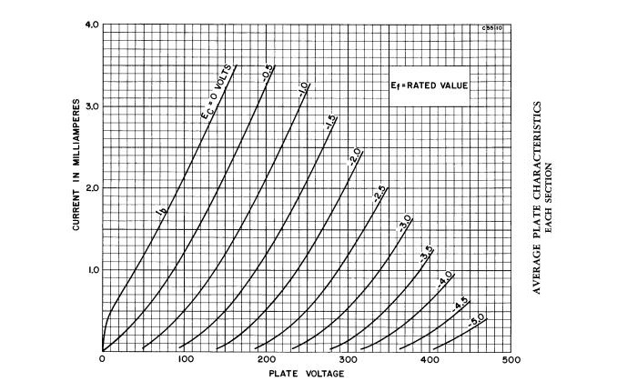
Figure 3 - Average Plate Characteristics For ECC83 / 12AX7 (Each Section)
We won't do all of them here (feel free to do this yourself), but the first preamps will both be examined. The closest grid voltage to -0.94V is -1V, so if we look at the 1V curve and find the plate voltage (135V), we can see that plate current will be almost exactly 1mA. This is quite close enough. From the graph, we can also judge linearity - this is at the bottom end of the curve where it is quite 'bendy' (look at the deviation from a straight line). This indicates that distortion will be fairly high.
The second preamp has a grid voltage of -1.6V (1.5V is close enough), and a plate voltage of 190V. While this can't be reconciled from the chart (the current should be a bit under 1mA), it's probably within the normal spread of valve operation. Again, distortion will be fairly high, but this is a guitar amp, after all.
AC analysis is harder, and much harder than a transistor amp. Part of the reason is that valves have comparatively low gain, where transistors can have extremely high gain if used with a constant current source as the collector load. A single transistor can have a voltage gain of several thousand, and with high linearity. Since the amplification factor of a 12AX7 is 100, that's that maximum theoretical gain you can get - in real circuits it will always be less. In addition, a valve can't conduct fully, bringing the plate voltage to zero. From the chart (again), the maximum possible current through the plate resistors is 1.8mA (180V across 100k, and 70V across the valve), and even with a grid voltage of zero, the chart shows the minimum plate voltage is about 80V - close enough to the 70V measured before. The anode voltage can only become less than 70V with grid current - as noted earlier, this distorts the input signal if it comes from a high impedance source.
Preamp #1 can therefore swing the anode a maximum of 250V, and a minimum of 70V - that's plus 115V and minus 65V ... decidedly asymmetrical. This may have been done for a reason (distortion 'tone'), or might be completely accidental. Either way, if guitarists like the sound, then that's all that really matters. Preamp #2 is almost the exact opposite, it can swing by +60V and -120V. The voltage gain is given by the formula ...
Rsource = rP + ( µ × RK ) = 80k + 100 = 80k close enough
Rtot = RP || Rload = 100k || 1M = 90k
Av = µ / (( Rsource / Rtot ) + 1 )
Av = 100 / ( ( 80 / 90 ) + 1 ) = 53
The apparent gain will be lower (or much lower) as the stage is pushed into distortion, so the calculated gain only applies for small signals (output voltage of no more than ~3V RMS). Based on the measurements taken from the test circuit in Figure 1, we can safely assume that distortion will be over 5% at any level greater than 10V RMS, developed from an input voltage of about 200mV. Somewhat surprisingly, 5% distortion is not easily audible with a single instrument such as an electric guitar. As the volume control is advanced, the load impedance on the stage changes, and also depends on the setting of the volume control for channel 2, because the resistors are joined. There are also capacitors that shape the response, giving an overall treble boost at all settings of Volume 2. The other channel (Volume 1), suffers a small HF loss at most settings, but not enough to be of any concern. All controls are interactive to a degree, but it's unlikely that any player would even notice.
You can also see that the 2.7k cathode resistor is bypassed with a 680nF cap. This creates a 6dB/ octave rolloff below about 100Hz. As you can see, there are many interdependent parameters, and it is impractical to try to analyse every nuance. Adjusting either volume control affects the level of signal from the other, treble is boosted, bass cut and we haven't even reached the tone controls.
The mixer stage is based on the second valve, and this is simply an amplifier with a direct-coupled cathode follower. Gain of the voltage amp stage is easily calculated ...
Rsource = rP + ( µ × RK ) = 80k + 100 = 80k close enough
Rtot = RP || Rload = 100k || ∞ = 100k
Av = µ / (( Rsource / Rtot ) + 1 )
Av = 100 / ( ( 80 / 100 ) + 1 ) = 55
This is again only for small signals. The cathode follower is designed to provide the tone stack with a low drive impedance, and the output impedance is easily calculated ...
rK = ( rP ) / ( µ + 1 )
rK = 80k / ( 100 + 1 ) = 790 ohms
In theory, this value is in parallel with the external cathode resistance, but it's so high it can be ignored. It is important to understand that even though the impedance seems low, the current capability is extremely limited. The peak current is limited by the valve plate resistance and the cathode resistor, so your expectation should be that the maximum will be a few microamps at most. Consequently, valve amp tone stacks are invariably high impedance, using 250k-1M pots.
The tone stack is shown below. While the general scheme is very common, values are changed by different makers to get their 'characteristic' frequency response/ 'sound'. Any number of different values are used, and the controls don't always have the expected behaviour. Just look at the response with only the treble pot fully advanced. While one might expect that this would reduce the bass, it does no such thing.
Figure 4 - Tone Stack, Including Response at Various Settings
Attempting to perform a mathematical analysis of any tone stack is rather pointless at best. It's all about the sound, and the maths are unimportant. I suspect that as often as not, the values are selected empirically (i.e. by trial and error), with the end result based on the preferences of a few selected players. If they can get the sound(s) they like, then everyone's happy. I freely admit that the tone controls for the Project 27 guitar amp were determined by experiment. Some simulations were run first, but the final values were selected by sound. The general scheme of the Marshall (above) and the P27 guitar preamp is (almost) identical, and few major manufacturers have deviated far from this model which is attributed to Fender in the earliest guitar and bass amps. It's worth noting that the response is affected by the load impedance - even a relatively small change can make a big difference to the way the controls perform.
For those who want to see (and experiment with) different types of tone controls should see Duncan Amps for a handy calculator that has the Fender and Marshall stacks, and includes several variations as used by other makers. Over the years, many people have experimented with traditional hi-fi type tone circuits (including active versions), but they seem to be almost universally disliked by most guitar players. This is reasonable - they just don't sound right, and no amount of messing about seems to help much. This hasn't stopped a few manufacturers from using them, but they are far less common than the Fender/ Marshall arrangement.
The so-called 'phase splitter' shown below is one of the most common in use for guitar amps. It's simple, and provides plenty of drive level to the output valves. Unfortunately, it can provide way too much drive for a sensitive valve like the EL34, and can easily drive them into fairly heavy grid current, as well as cause them to turn off completely. The effects of this will described later.
Figure 5 - Phase Splitter (Typical)
The circuit may be recognised as being essentially a long-tailed (or differential) pair, and that's exactly what it is. The 470 ohm resistor develops sufficient voltage to bias the valves correctly, and the 10k resistor couples the signal from the cathode of the first section back to the cathode of the second. Because of the limited gain of valves, the anode resistors are almost always different values, in an attempt to match the output levels. Feedback is applied to the second half of the circuit, and is coupled back (via the cathode) to the first half. Not ideal perhaps, but it works well in practice. Other amps use different techniques for negative feedback - this is just one example.
Ideally, the signal from each output should be identical ... assuming that the output valves are identical. It is preferable to include a pot in series with one of the anode resistors so the gains can be matched exactly to the output valves, but this is likely to be found only in hi-fi equipment. The feedback signal comes from the secondary of the output transformer, and linearises the output stage. This is only possible up to a point, because phase shift within the transformer will make the amplifier oscillate if excessive feedback is used. There are quite a few variations on this general scheme, but the net result is pretty much the same.
The presence control simply removes some of the high frequency feedback, boosting treble. All in all, this is not a bad circuit. Its linearity is acceptable, but is not up to the standards we expect for high fidelity amps. For a guitar amp, there's usually no problem, since the added distortion is part of the sound. The circuit is often driven from a fairly high supply voltage, and Fender generally uses a 12AT7 for the phase splitter. This has less gain and higher plate current capability, but otherwise works virtually identically.
Because of the requirement to get symmetrical drive to the output valves (preferably with adjustment to allow for small differences), this is not a design I've ever liked. It has the advantage of being cheap to implement though, and this is an important consideration for any manufacturer. It will drive 6L6GC or EL34 valves to clipping easily, but will usually have difficulty with KT88s running from a 600V supply, because it cannot provide enough swing to drive the valves properly. Many Marshall amps use (or used) 6550 valves in the US before EL34s were readily available. This worked because the supply voltage was comparatively low (typically about 470V).
There are three common phase splitters that are commonly used. The cathode coupled type we've looked at already, but the added pot allows the gain of each section to be matched perfectly. The second type is the paraphase, which is simply two normal voltage amplifier stages connected together, with attenuation between the first and second stages to match the gain. The pot shown is essential, as it is almost impossible to get a good gain match without it - especially if valves are changed. The gain may also change with ageing, requiring possible periodic adjustment. The paraphase splitter has the advantage of having the highest output swing of all the types, but has no inherent distortion matching like the cathode coupled design. Note that there are two completely different circuits that are both known as 'paraphase'.
Figure 6 - Two Common Phase Inverters (Phase Splitters)
The paraphase (version 1) shown is (to me at least) one of the worst examples of a phase splitter, because it has no 'self-correction' ability, and the output level from each section will change as the valve ages. It's often shown with no pot to allow the levels to be balanced, and in that form it should never be used. The second form is shown shown below (version 2), and it works by using the second valve as a unity gain inverter, which improves matters somewhat. Different value plate resistors may still generally needed. You may see the version 2 paraphase splitter used with the first half being a pentode for additional gain. In that case, the two valve sections will generally have separate cathode resistors and bypass caps.
Figure 6A - Two More Common Phase Inverters
To my mind, the best phase splitter is the balanced/ split load type, also called a 'concertina' phase splitter. If the anode and cathode resistors are closely matched, the signal level from each output is virtually identical. Gain is less than unity (typically about 0.9), and the maximum output swing is quite limited. It can also be relied upon to do things that you really don't want if it is pushed into clipping or the output valves draw grid current at maximum drive. When the balanced load splitter is followed by amplifier stages, we can get the same level as the paraphase, but with very well matched output levels. Some small range of adjustment might be needed to ensure the gain stages are matched though. If the gain stage is coupled to cathode follower outputs, this enables the output valve grid resistors to be kept to a sensibly low value, and provides the best drive capability of any of the circuits. This arrangement does use rather more valves than the other methods, which limits its usage due to cost.
Please note that the circuits in Figures 6 and 6A and the values shown are representative only, and the four circuits shown are not strictly part of the analysis process. They were included simply because it is necessary to show the options that are used.
The power amplifier section is probably the most controversial, the hardest to get right, and by far the most expensive. To understand it completely, you need a good grasp of transformer analysis, and a better than average understanding of how to get the most from output valves, while ensuring that they are not overloaded even when driven very hard. While the transformer requirements are fairly relaxed for guitar amps (the upper frequency limit needed is only about 10kHz, but at least 30kHz is needed for good stability when feedback is applied), good hi-fi transformers are difficult and expensive to wind.
Figure 7 - Power Amplifier Stage
There are countless ways to mess up a valve power stage, with most errors resulting in reduced valve life. In some cases destructive voltages or currents can be generated simply by having a 'protective' fuse or standby switch in the wrong place. Errors are quite common, with the most common of all operating the screen at a voltage that is too high. Evidence of this is glowing screens when the amp is driven hard (whether by signal generator or guitar is immaterial). While a resistive dummy load is usually more challenging than a real speaker, excess screen current is very common into both with overdrive. Providing a reduced screen voltage is ideal, but complicates the power supply and increases the cost.
Everything is a major compromise with any valve output stage, because loudspeaker loads are nominal - meaning "in name only". An 8 ohm speaker will exhibit an impedance of 8 ohms over a small frequency range, typically at about 200Hz. Below this frequency, the impedance rises due to resonance, and above 200Hz the impedance rises because of voicecoil semi-inductance. This makes the design of a reliable power stage difficult, and even if the exact characteristics of the speaker load are known in advance it will be a compromise in all cases.
None of this is a real issue with valve hi-fi amps, because they may only clip occasionally. The problem is far worse for guitar amps, because they are often driven into full (square wave) clipping. Transistor output stages love full clipping, because transistor dissipation is at its lowest, but not so for valves. Plate dissipation is often fairly high, and screen dissipation is at its greatest. There are some other effects that will be looked at shortly - these involve often serious voltage spikes, but the reasons are not immediately apparent.
In the meantime, we can look at a more-or-less typical 50W output stage - the only real difference between this and the 100W version is the use of 4 output valves and a different output transformer. The voltages usually applied are at the very top end of the EL34 specification - especially G2 (the screen grid). While operating G2 at a higher than ideal voltage does increase output power, it also shortens the life of the valve. The reduction can be dramatic if the amp is pushed hard most of the time, and it's common during testing (and playing) to see the screen glowing a fairly bright red. This is never a good thing.
While most valve power amps provide a means to adjust the negative grid bias voltage, few provide a pot that allows the valves to be properly balanced. Not providing this adjustment is a real nuisance, because matched valves must be used. Many offerings of 'matched' valves must (or so it seems) consider them to be 'matched' if they look the same - they often certainly don't behave the same. Yes, valves should be matched, but the problem is where? At full power? Half power perhaps? At what voltages (plate, screen, control grid)? There are too many things to match, and valves just aren't that simple.
The output transformer is a much misunderstood item in all of this. There are many different ways that the (nominal) primary impedance can be worked out, but most are rather complex. A somewhat simpler procedure that gives the info you need is described - it may not have the finesse of the established methods, but it does give a more than acceptable result, especially since the actual load impedance is so variable. For this, we will assume that the amp will operate in Class-AB1, indicating that control grid (G1) current will not be drawn under normal (not clipping) operation. Almost all valve amps will draw grid current when driven into overload - it's pretty much unavoidable.
We need to examine the load lines for the output valve to be used, in this case, the EL34. Maximum plate dissipation is 25W, maximum cathode current is 150mA, and the maximum quiescent anode voltage is 800V - too high for normal use, so we'll reduce it to 600V. Screen voltage will be 300V - well within ratings. Some degree of interpolation is needed from the graph, since the screen voltage for the EL34 is shown as 250V, but as a first approximation, we can ignore the difference. The choice of 600V and 300V is deliberate - it allows the use of a voltage doubler supply, with the screen powered from the centre tap which is at half voltage. It's not unrealistic to expect about 60W from this combination, but to allow for transformer losses we'll aim for 70W to see what happens.
Before we start, it needs to be explained that the output transformer is centre tapped, and anything that happens at one end of the winding happens at the other end, but inverted. If one end of the primary is pulled to zero volts, the other goes to double the supply voltage and vice versa. This is an AC phenomenon only, and the minimum frequency depends on the inductance and core saturation limits of the transformer. So using the example to follow, if there's an RMS voltage of 375V on the anode of each valve, then the total voltage across the transformer is double that, namely 750V.
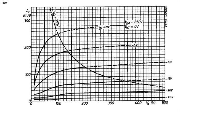
Figure 8 - EL34 Transfer Characteristics
From the above chart, we can see that at a grid voltage of zero, the voltage across the valve will be about 20V at 150mA. This is somewhat optimistic (or highly unrealistic) IMO, and it's normally closer to 70V in a real circuit. This means that the maximum negative voltage swing is 530V (600 - 70 volts), and the maximum positive swing is 1,130V (600 + 530 volts). The RMS voltage is 750V from plate to plate. Since we expect to get 70W output, and assuming an 8 ohm load, the voltage needed for the speaker is 24V RMS in round figures. (If you can't see how these figures were obtained, please refer to the beginners' section of the ESP website). The turns ratio is simply 750 / 24 = 31:1, and since the impedance ratio is the square of the turns ratio, this is 961:1, close enough. Maximum (peak) current in the load is 24 * 1.414 / 8 = 4.25A, so peak plate current will be 4.25 divided by the turns ratio of 31:1 (137mA) at about 70V. This is well within rated maximum for the EL34. (Note that most valve specifications are for average (current, power, etc.) unless specified otherwise.)
The plate to plate impedance needed for the transformer is therefore 961 * 8, or 7,688 ohms. Having determined this, look at the Figure 8 chart again, and verify that the plate dissipation is not exceeded at any plate voltage, from the lowest to the highest. At voltages above 600V, the valve is either turned off (Class-B) or is in the process of doing so (Class-AB). In general, if the current drawn at exactly half the supply voltage is within limits, the design should be alright. Looking at the current needed with 300V on the plate (which is about 18V across the 8 ohm load, or 2.27A), again we divide the peak output current by the turns ratio, and obtain a value of 73mA. From the chart, this is still within the valve's ratings, and should work fine.
The bias current needs to be such that there is minimal crossover distortion, but must be well below the maximum. A continuous plate dissipation of perhaps 15W is the most we should use to avoid causing stress, so current needs to be no more than perhaps 15W divided by 600V - around 25mA is about right (although less is better). The negative grid bias will be close to -30V. Allowing for output transformer losses of up to 10W (I'd rather be pessimistic than optimistic here), it should produce about 60W easily enough. The Miniwatt Technical Data manual suggests that it's possible (although I'm not sure I agree, and nor does anyone else I've spoken to) to get 100W from a pair of EL34 valves, using an 800V plate supply, 400V for the screens, and using an 11,000 ohm plate-to-plate impedance transformer. The figures obtained above are generally in agreement with this, but the Miniwatt data appears to be theoretical. For example, an 11k transformer makes no allowance for transformer losses or power supply collapse under load.
The above (like the Miniwatt data) assumes that the plate and screen voltages do not collapse under load. In reality, both voltages will fall - the amount depends on the use a properly sized power transformer that will minimise the voltage collapse. It is unrealistic to expect the regulation to be much better than 10% though, and this represents a significant drop in power. Although the stage was designed for 70W output, it will be closer to 50W after the supply voltages have fallen. To compensate, the turns ratio might be reduced to perhaps 30:1, giving a 7.2k plate-to-plate primary impedance.
 | Please note that this (and the following schematic) is a theoretical circuit, and it has not be built
or tested. It's more of a thought experiment than anything else, and that's all it's intended to be. The peak plate voltage is well within specifications, but is somewhat
higher than "typical" guitar amps, and this will lead to valve base flashover unless the diodes are used. With the often dubious valves one might get today, the circuit
will be close to all limits into a resistive load. Because of the configuration, the stage has little reserve to accommodate overloads, and may suffer compared to a
more 'traditional' design - which suffers to some degree most of the time. In general, it's better to sacrifice a bit of power to ensure that valves are not stressed, and this ensures much longer valve life. It can also provide a generous allowance for abuse - as a guitar amp, abuse is perfectly normal for a great many players. Output stage overload characteristics are part of the sound, and the amp should be designed to ensure that bad things don't happen, regardless of how hard it's driven. |
For what it's worth, the details of a 130W Musicman amp and output transformer are rather similar to the above thought experiment. Output primary winding resistance is 220 ohms (plate to plate), leakage inductance is 33mH, and the transformer ratio is 24.25:1. This gives a primary impedance of 4,700 ohms (8 × 24.25²). Plate supply is 695V and screen supply is 347V, and the amp runs with 24mA bias current per valve (4 x EL34). It gives a clean 120W, equivalent to 60W from a pair of valves with a 9,400 ohm plate to plate primary impedance and the same supply voltages. (Information provided by Phil Allison.)
If everything is worked backwards, this turns out to be very close to the original specification that was determined above. A correction is needed for the higher supply voltage, and another to the output transformer which is driven by a pair of valves each side (which requires half the transformer impedance). I'd be rather uncomfortable operating with such a high plate voltage for an amp that's likely to be thrashed, but the Musicman does include diodes from plate to earth on the output transformer, so waveform spikes are not an issue.
Since this amp produces 120W, that's 31V RMS across the load. Given the turns ratio, we get 751V RMS plate to plate, or a swing of 1062V at each anode. Allowing for the supply voltage collapse (say 10%), this means we get a plate supply of about 630V at full power. That allows for 70V across the valves when turned on fully, and a first guess of about 30V across the transformer winding. Given the peak current of 226mA (113mA through each valve), and the winding resistance of 110 ohms, that comes to 25V, so it all falls pretty neatly into place. This was not intended to be an exact calculation, and the initial assumptions were nothing more than educated guesses.
That the maths worked out to within a few volts isn't bad for what amounts to a complete analysis of the output stage at full power. The same basic (quick and dirty) calculations will work with almost any amplifier, so plate to plate load can lose its mystique - there's really nothing difficult about it.
The traditional guitar amp circuit has many compromises and shortcuts, and in general, cannot be expected to provide long valve life. If pushed very hard, valves may only last a matter of weeks. Other factors can also create even more expensive problems. One thing that many guitar amps do very well is create high voltage spikes on the output valve anodes. These are the result of a suddenly collapsing magnetic field, as happens when the output stage is overdriven. The voltage spikes can reach as much as 5kV ... well in excess of the 2kV rating for an EL34, and often in excess of the insulation breakdown voltage for the output transformer. The results are all too common - carbonised valve bases (and sockets unless they are ceramic), internal valve damage, and shorted turns in the output transformer. It is uncommon for severe spikes to be generated if the amplifier is used sensibly, but if a guitarist happens to like the sound with everything turned up to 10 (or perhaps 11), then spike generation is pretty much guaranteed.
These are all real faults, and I've seen the results many times years ago when I serviced amps. They still exist, but now cause damage more often than I was used to seeing. Transformers are not made to the same standards as they used to be, and nor are valves. The result is inevitable - amplifiers fail. The arrangement shown below will help, especially if the screen voltage is reduced, but this is often not possible without fairly major changes to transformer designs. The following is based on the design discussed above.

Figure 9 - Improvements To Power Amplifier
By adding the 'catch' diodes from each anode to earth (ground), the voltage is prevented from becoming negative. This absorbs the energy that would otherwise just create a high voltage spike, and will limit the plate voltage of each output valve to double the supply voltage - and no more. This simple addition eliminates the high voltage spike problem, and is included in some guitar amps. Note that any spikes generated as a result of leakage inductance do not appear at the speaker output - they are confined to the primary side of the transformer because leakage inductance (by definition) is not coupled to the secondary. The main spikes that result from the inductive speaker load do appear on the secondary.
The other addition is the pot for bias balance. This allows the valves to be set so that exactly the same bias current flows through each, and completely eliminates DC in the output transformer. Since there's often a relatively high ripple voltage on the high voltage supply, speaker hum can also be eliminated (or at least that part that comes from the power amp). 10 ohm resistors in the cathode circuit of each valve allow the current to be monitored accurately and simply. Measure the voltage across the resistor, and for (say) 15mA bias current, you should measure 150mV across the 10 ohm resistor. These simple additions make it so much easier to set the amp up properly, especially when a new set of valves is installed.
To give you an idea of how easy it is to make a mistake in a circuit design, just before publication I noticed that the bias balance pot I originally had was badly flawed. Bias was simply applied to the pot wiper, with the balance resistors going to earth. I then remembered the number of trimpots I've seen where the wiper was intermittently open circuit after a few years and saw my glaring error. With bias applied to the wiper, an open circuit would disconnect the bias completely, leading to valve destruction.
As a result, I had to re-draw Figure 9 to ensure that an open trimpot wiper would apply more bias (you get some extra distortion, but no blown output valves). The result is shown, and this is a fail-safe method. It does require one more resistor, but that's a small price to pay. Should the wiper disconnect for any reason, the negative bias voltage will increase (become more negative), and will be the same on both valves.
This is just an article - not a real amplifier, but had it actually been built as originally described there was a disaster just waiting to happen. That it would happen sooner or later is inevitable, and this is the kind of diligence that one would hope for from established amp makers. I don't recommend that you hold your breath though.
I've been wondering for well over 30 years why bias balance and cathode resistors aren't standard practice, and in all that time, nothing has changed for the majority of popular designs (there are some that do include the cathode resistors, but not Fender or Marshall). It's actually fair to say that the same basic mistakes have been with us for over 50 years! One would think that was quite enough time for major manufacturers to get their acts together, but perhaps they need another 50 years to work out what they've been doing wrong. Before the reader thinks that this is simply my opinion, it's not - it's a fact.
Each and every problem described can be created at a gig or on the bench at will, using everyday standard playing techniques or test methods. The only real surprise is that more amps don't fail more often, because there's absolutely nothing to stop them from doing so. It must also be understood that some of the mods needed to improve reliability will affect the sound (such as the diodes), so the owner may be less than pleased with the end result. Equally, and provided the owner is unaware of the change, they may never notice.
In order to understand the importance of the various functions of a transformer, we need to examine the equivalent circuit. Of all the characteristics of a transformer, leakage inductance is the most insidious, and causes the greatest number of problems. Loss of high frequencies is the simplest of these, but things change when a valve amplifier is driven into heavy distortion. There's a lot more information available in the Articles Section, but the essentials will be covered here because they are important.
Figure 10 - Transformer Equivalent Circuit
The circuit shown above describes almost all known transformers. There will always be at least some of the parameters shown, because nothing can be perfect. The primary inductance determines the lowest frequency the transformer will pass, and depends on impedance. For the hypothetical transformer described above with a primary impedance of 8.7k, we'd need an inductance of at least 34 Henrys for a -3dB frequency of 40Hz. The inductance of an output transformer is not a fixed quantity - as the transformer is pushed into saturation (at low frequencies), inductance falls off rapidly, and the inductance even changes with signal level. At speaker resonance, the reflected impedance to the plates of the output valves will be far greater than at midrange frequencies. With reduced current comes higher voltage swing, which may allow the transformer to saturate.
To prevent saturation, you need more primary turns to provide sufficient inductance, and more turns means higher resistance because thinner wire has to be used. There seems little doubt that most guitar amp transformers have too little iron in the core, and will saturate quite readily at the lowest frequencies, but this is all part of the sound. Whether the 'sound' was by accident or design is difficult to know, but I'd tend to guess 'accident' that happened to work. Few guitarists would be happy if the stock transformer were replaced by a 'better' version that didn't provide the sound they expect.
As part of the overall design of an amplifier, the output transformer losses need to be considered. The main cause of loss is the winding resistance in the primary, and though this can be less than 100 ohms either side of the centre tap, it may also be somewhat higher. For a given inductance, a smaller core needs both more turns and thinner wire, and this increases the resistive loss. All resistive losses are converted to heat, so to make a cool-running transformer you often need to use a core that's larger than expected.
The transformer's insulation needs to be able to withstand the maximum peak-to-peak voltage that can be generated (1.2kV) plus a generous safety margin (remember the spikes!). Winding resistance must be kept low to minimise resistive (copper) losses and keep the temperature of the transformer within reasonable limits. Every Watt lost in the transformer is a Watt that doesn't get to the loudspeaker, and only contributes to making the transformer hot. With few (if any) exceptions, commercial valve amp transformers are made as cheaply as possible. Losses are generally much higher than desirable, and the transformers run hotter than we might prefer. Unless high temperature insulation is used, the risk of insulation failure is greatly increased when the temperature is increased. Losses in any transformer are unavoidable, and to really minimise them requires a core that's a great deal larger than those normally used. This is simply not an economical proposition, and the end result ends up weighing too much for anyone to easily move it around.
Leakage inductance in a transformer is created by imperfect 'entrapment' of the magnetic lines of force within the core. Many techniques are available to minimise leakage inductance, such as interleaved windings (primary-secondary-primary-secondary, etc.) or using toroidal cores. In general, it's unrealistic to expect the leakage inductance to be less than around 25-50mH for a 20-30H primary inductance, other than with very expensive hi-fi transformers. This low inductance can still store considerable energy though, but it is a combination of leakage inductance and (more significantly) load inductance that is responsible for the high voltage spike problem referred to earlier.
There is something else that makes the high voltage spike problem worse - the power output valves' input capacitors! This may sound silly, but you need to follow the reason carefully. When an amp is driven into clipping, the spike is caused because one valve is turned on fully, and the other is off. At the moment the condition reverses, the leakage inductance of that part of the primary winding that was conducting current suddenly sees the current stop, as does the inductive loudspeaker load. When the current through an inductor is interrupted, a voltage spike (back EMF) is created - for this reason we always add diodes across relay coils for example.
At the onset of clipping, the transition between on and off for each valve is relatively gradual, and there is always some load across the transformer. This dissipates the back EMF harmlessly. Anyone who has looked carefully at the waveform of a valve amp as it's pushed into clipping will know, clipping is accompanied by what looks remarkably like crossover distortion. Well, that's exactly what it is! But how?
When clipping is moderate, the output valves are always pushed to the point where control grid (G1) current flows. Since this is diode action, it charges the coupling capacitor, which has the voltage across it increased. Therefore, when the signal goes negative again, the negative bias is increased, and so does the maximum negative swing on the valve grid. This ensures that the valve cuts off more completely than before. Drive the amp harder, and this extra negative voltage ensures that there is a 'dead time' between one valve turning off and the other turning on. During this period, there is nothing to damp the back EMF spike, which as mentioned earlier can reach 5kV! It's not just the leakage inductance of half the primary winding, but the total leakage inductance plus the inductance of the load at work. It's difficult to see exactly how the voltage across the coupling caps is increased, so the following diagram may help somewhat.
Figure 11 - Increased Negative Bias With Grid Current
The simulation above shows the normal (unclipped) operation, and that with overdrive and consequent grid current. The diode shown is 'virtual', in that it is a function of the valve itself. The coupling capacitor is normally charged to present -30V to the grid from the bias supply, but this becomes more negative to -39V when the drive voltage is increased. If the amp was properly biased with -30V, it will be severely under biased with -39V on the grid. This ensures that both valves can be off simultaneously - the root cause of the problem. Add to this that the minimum voltage is now -85V, which will normally be enough to prevent any valve conduction - regardless of plate voltage. Push the amp even harder, and the problem gets worse.
Since the amp is being pushed hard, the plate and screen supply voltages fall, so while the stage is getting more negative bias, in order to maintain linearity (or even conduction) it needs less. There is no easy way to compensate for all of these things happening at once.
The voltages applied for each case in Figure 11 were 30V peak (10.6V RMS) and 60V peak (21.2V RMS), via a more or less typical source impedance of 47k. These signal voltages are easily available from the cathode coupled or paraphase phase splitter. The values are simply to show the effect, but are not intended to represent an actual circuit. While bias and signal voltages will differ, the effect is identical. The bias shift can be reduced by using a driver transformer (too expensive), direct coupled solid state drive circuitry, or by driving the cathodes of the output valves with a transistor (Musicman - also uses catch diodes). While some people on forum sites seem to have noticed the crossover distortion during heavy clipping, only a few have identified the problem. No-one has pointed out that the crossover distortion is inaudible along with clipping, nor has anyone looked at the spike waveform when the load is inductive (such as a speaker, or an inductive 'power soak' external attenuator).
Suggestions to 'cure' the problem include increasing the size of the grid stopper resistor (slows the process and reduces high frequency response, but not much else) and/or reducing the size of the coupling caps (reduces bass response). This changes nothing, but allows the blocking condition to recover faster. These techniques fail to prevent grid current and coupling cap charging, and do not address the reduction of plate and screen voltages under full load conditions, which requires that the bias voltage be reduced to maintain conduction through the transition from one valve to the other.
In addition, as the power supply is loaded by the plate current (and screen grid current), the voltage falls. This doesn't have much effect if it's only the plate voltage that collapses, because the plate current is most strongly influenced by the screen grid. However, because the screen supply is almost invariably unregulated, this falls too. A relatively small reduction of screen voltage makes a big difference to the plate current and the bias voltage needed for a specific bias current. When the screen voltage falls, even the normal negative bias voltage is too great, but when it's increased because of control grid current charging the input caps, the effect is magnified. This increases the period where both output valves are completely turned off. It's worth listing all the things that lead to increased crossover distortion and/or voltage spikes during overdrive conditions ...
The last of these factors will generally be minor, and will only apply during sustained overdrive. The overall effect of this would need to be measured carefully to determine if it causes a problem. Meanwhile, the negative bias voltage is also reduced because of transformer loading, but the reduction will be slow, and unable to keep up with the dynamics of the applied signal. As a result, the bias current can shift all over the place while the amp is being used. The effects are unlikely to be audible (especially at high volume), but are all certainly measurable.
The only way to completely prevent load impedance induced back EMF spikes from happening is to add catch diodes to kill the spikes by preventing the anode voltage from swinging below zero volts, add a heavy duty Zobel network (perhaps 10 ohms/ 25W in series with a 10uF capacitor) that maintains close to the correct impedance at higher frequencies, or only use a resistive load. The latter is obviously impractical. The catch diodes ideally need to be fast recovery types, otherwise they may be destroyed by the reverse energy through them at higher frequencies. A series string of 3 or 4 UF4007 (ultra-fast, 1,000V, 1A) will normally be adequate, but larger diodes will provide a greater safety margin. A Zobel network as described will dissipate significant power, and is not practical. An alternative that I have seen used is to install a low value (perhaps 220pF or so) high voltage capacitor across the full primary winding. This lowers the effective frequency of the spike ringing waveform and can reduce the amplitude to a 'safe' value.
Be aware that adding the catch diodes (or a Zobel network) will change the sound of the amp in heavy clipping - it may lose 'bite', since the spike waveform produces considerable high frequency energy. To some players, this may be unacceptable, but reliability and high voltage spikes don't mix. Should the valve suffer flashover at the base (most commonly between the plate and heater connections because they are next to each other), further damage is likely - especially if the initial arc carbonises the Bakelite base and creates a low resistance path.
Figure 12 - Increased Negative Bias Causing Crossover Distortion
The above is a simulation, but shows the effect of increased negative bias as the valves draw grid current. At the onset of clipping the effect is not noticeable, but as drive is increased, a kink becomes visible around the zero-crossing region. If pushed hard enough, this will become more visible, turning into very obvious crossover distortion. Provided this only happens when the valves are clipping, the sound quality is not affected - crossover distortion contains exactly the same harmonic structure as clipping, but the phase is displaced. By itself, this distortion is not a problem. It only gives rise for concern if the amplifier generates voltage spikes as a result of the valves turning off completely.
It would be nice if there were a way to limit the positive-going peaks to ensure that grid current is minimised, but unfortunately it's not that easy. The gain of output valves is highly dependent upon the load, and a speaker is not a fixed impedance. Near resonance, the impedance is high, the valves are lightly loaded, and even a tiny grid voltage swing can cause heavy clipping (and possibly output spikes). However, a means of preventing the grid voltage from attempting to swing positive can be achieved (albeit with some difficulty), and is a good idea if it can be done without unwanted side effects.
If what you've read so far looks a bit scary, there's another common error waiting to catch you out - the placement of the standby switch or HT fuse. So many problems that could have been sorted out years ago, but they still persist to this day. The standby switch/ HT fuse issues will be covered in the next section, as these are part of the power supply.
While you could be forgiven for thinking that no major manufacturer could possibly screw up a power supply design, sadly, I'm afraid you'd be wrong. One of the worst is common with Marshall amps, and is caused by the way the negative bias is derived. To blow the internal HT fuse in some Marshall amps, all you have to do is disconnect the power lead (or switch the amp off), wait for about 2 seconds and turn it back on. All output valves conduct hard because they have almost no bias at all. This often blows the internal high tension fuse and will almost certainly damage the valves to some degree. The bias voltage takes about 3 seconds to reach a safe value, but discharges to an unsafe voltage in as little as one second when power is removed. How stupid is that? The reason can be seen in the power supply schematic shown below.
The errors found in many guitar amp circuits seem to come and go. Sometimes a 're-issue' model will be produced, and some will have original mistakes corrected, others not. There appears to be no rhyme or reason as to how these errors don't get noticed, and some are a great deal worse than others. You can look at any number of schematics for famous (and infamous) guitar amps. Some will have no apparent errors, while others have managed to incorporate every bad decision ever made. It's usually possible to spot at least one error (or at least 'sub-optimal' circuit arrangement) in most designs, but some have far greater consequences than others.
Figure 13 - Power Supply Schematic (Marshall, Typical)
The bias supply should ideally be obtained from a separate winding (or a tap on the main HT winding, as used in some Fender and Marshall amps as shown below). This provides a low impedance source, so bias voltage is established almost instantly when power is applied. It is inevitable that the bias filter caps in the circuit shown will charge slowly because they have a 220k resistor in series. By loading the output with the voltage setting pot and associated resistor, a rapid discharge is assured. The slow circuit shown above is faster than the heater warm-up time for the output valves, but it all falls apart if there's a momentary (around 2 to 10 seconds) mains failure for some reason. Remember that the valve cathodes will still be hot enough to emit a vast number of electrons, and after a short mains interruption there's no negative bias.
Since the output stage negative bias is the most important voltage in the entire amplifier, it beggars belief that pennies would be pinched in this critical application. In general, the very best way to obtain the bias voltage is from a separate winding, or at least a tapping on the HV winding. Using a separate winding gives the opportunity of full wave rectification, almost instant application of bias voltage, and it can be held up well after the power is removed as a safety precaution. However, the negative bias voltage must never be regulated in any way. It must vary with mains voltage so that normal operating conditions are maintained as the mains supply varies (which it does all the time).
The remainder of the circuit is traditional, and is mostly alright. An exception is the placement of the 500mA HT fuse. This fuse will only blow if there is a heavy load through the output transformer and (possibly) the filter choke. When the current through a choke (an inductor) is suddenly stopped, a high voltage back EMF is developed - yes, same problem we discussed earlier. Since the output transformer is connected to the same point, there may be a rather large inductance involved, and the voltage spike can cause valve base flash-overs or transformer insulation failure. I concede that a HT fuse failure is fairly uncommon, and almost always means there is a fault (such as a brief mains interruption!). Still, for the sake of a couple of diodes ...
Figure 13A - Fender Power Supply Schematic (Bassman 100)
Fender goes one better as shown above - in a great many models, the standby switch is located where Marshall amps have the fuse! Never mind that trying to break 400-odd volts DC with a normal switch is asking for trouble, but to locate the switch where very high transient voltages are (or can be) generated ... I don't think this qualifies as a wise move. At least the bias supply is a low impedance and will charge quickly. Two ordinary high voltage diodes will totally prevent the back EMF from causing any harm, as shown in the following diagram.
Figure 14 - Diode Clamp For Choke Flyback Voltage (Switch or Fuse)
The above arrangement requires two cheap diodes (1N4007 or similar), and prevents any back EMF spike from being created when either the fuse blows or when the standby switch is opened. A switch in this position will eventually fail, but it will last a lot longer if the high voltage spikes can be suppressed, thus helping to prevent the arc. Stopping the back EMF also protects the insulation of the output transformer and choke, potentially saving the owner from a very expensive repair.
At least one model of Fender amp had the standby switch between the valve rectifier and main filter caps. When the amp is switched out of standby, the result is that the rectifier valve sees as near as damnit to a dead short. Rectifier life can be expected to be far less than normal with such abuse. Speaking of valve rectifiers, there is absolutely no sensible reason to use them in any amplifier. Because they have significant series (plate) resistance, efficiency is poor, current handling is woeful compared to cheap silicon diodes, and they simply add more heat to the amplifier as a whole. A more-or-less typical 5U4 has a plate resistance of around 260Ω, and dissipates up to 13W. An original Tung Sol datasheet claims that the effective plate supply impedance is 75Ω, but the details as to how that was determined are vague. Good filtering is now comparatively cheap, because although high voltage electrolytic caps were uncommon for a while (after the end of the valve era), they are now readily available for switchmode power supplies. The DC supply can have better regulation, and no amplifier cares how the DC was created. If you really want to have 'soggy' DC rails, use silicon diodes and add series resistors - you can make the rails as soggy as you like.
It is very common that the filter capacitors used in valve amps (and especially guitar amps) are too small - often far too small. In the early days, they had to be limited in value because valve rectifiers can't tolerate high surge currents, but with silicon diodes this constraint is removed. A 5U4 was limited to around 40μF, which is pretty low for a decent power amplifier. The effect of insufficient capacitance is 100/120Hz hum added to the signal when the amp is driven into overload. Although this certainly adds to the 'sound' of the amp, the vast majority of guitarists prefer the sound if this hum is suppressed. Strangely, Marshall issued a 'service note' instructing repairers to disconnect one of the main filter caps (two of them in a common can). Don't believe me? See the Service Note for yourself. It's important to understand that valve rectifiers are simply a waste of space, and there is nothing they can do that can't be duplicated with a silicon diode and a series resistor (if you want a 'soggy' high voltage rail).
One other disaster needs to be covered before we conclude. Older Fender (and many other US made) amps commonly have a 'ground' switch, which connects either the active or neutral to chassis via a 47nF, 600V DC capacitor. While this is intended to minimise hum when the amp is used with an unearthed US mains outlet, for 220/240V AC countries it's best known as a 'death cap'. Connecting the active to earth via any capacitor of 47nF (whether intentionally or otherwise) is illegal in Australia, and no doubt in most other countries as well. The maximum permitted value (minimum certified Y2 Class) from active or neutral to earth is usually about 4.7nF - one tenth of the value used by Fender and most others. See Mains Safety (Section 8) for a detailed examination of this practice. Where fitted, this capacitor must be removed entirely - it's not known as a 'death cap' for no reason!
DC capacitors will fail at 240V because of internal corona discharge, which damages the insulation. Worst case is that the cap will become a short circuit (unlikely, but possible), and these caps can and do fail regularly. Most will be found to be open circuit after a few years of use, but for safety they should be removed completely and replaced by a nice safe air gap (i.e. nothing at all). In most countries outside the US mains outlets are earthed, so the capacitor is redundant but potentially dangerous. If you own a Fender amp (or anything else that includes a 'death cap'), have the capacitor removed, preferably sooner rather than later. The twin mains lead should be replaced with 3-core, with the earth (ground) green/yellow (or just green in the US) attached to a separate chassis bolt dedicated to grounding the chassis. Do not use an existing bolt or screw, and don't solder the earth lead to the chassis.
Valves generally run hot, but should never be so hot that anything other than the cathode glows red. Some transmitting valves may be an exception, but are well outside the scope of this article. Good air circulation around the valves is essential, and it's a really bad idea to place hot output valves anywhere near chassis mounted electrolytic capacitors. Electrolytics don't like heat at all, and it increases their leakage and reduces their expected life.
Good air circulation also helps to keep power and output transformers and filter chokes within a sensible temperature range. Like capacitors, the cooler they run the better. Less well known is that traditional Bakelite valve bases and sockets must also be kept cool. This indicates that mounting valves upside-down is probably unwise, but since we are so used to seeing problems with amp designs I don't expect anything to happen. Many valve manufacturers state the allowable mounting positions in their data, and 'any' is a common claim. If this is the case, what's the problem?
You will need to this test yourself, since it's highly unlikely that you'll believe the following claim ... Bakelite becomes conductive when it's hot. Yes, you read that correctly. If you have access to a meter that can register resistance above 20 Megohms it's easy to see, but even with a normal multimeter that can only read up to 20M you can still run the test. The test itself is as simple as can be - heat the valve base with a hot air gun, then measure the resistance between pins 4 (G2 - screen grid) and 5 (G1 - control grid). The valve base needs to be quite hot to get a reading, but I measured a drop from effectively infinity down to about 10 Megohms. As the valve base cooled, the resistance increased again, and was quickly off the scale of my meter. I also used a megohm meter that uses a test voltage of 1kV and will read up to 2G ohms.
This is not some isolated incident - it will happen with any valve having a Bakelite (phenolic resin) base, but because Bakelite compounds vary, it may or may not cause a problem. Although bias runaway is a fairly rare fault, some early Fender amps had to be modified because the output valve grid bias resistors were too large (Fender generally use 68k for a pair of 6L6GC valves, Marshall amps use 220k, and it's the same for 1 or 2 pairs of output valves ... there are many different versions though and values vary).
High resistance from the bias supply makes the control grid far more sensitive to leakage from the adjacent screen grid pin. In many data sheets, the maximum value of the control grid resistance is specified. For the EL34 this is typically around 500k for Class-B operation, but few manufacturers use higher than 220k, and lower resistance is obviously better. This is another tradeoff, since it places a greater load on the phase splitter which increases distortion and reduces signal swing. For (presumably) this reason, Fender use a 12AT7 which can be run at higher current and drive the lower resistance bias feed resistors.
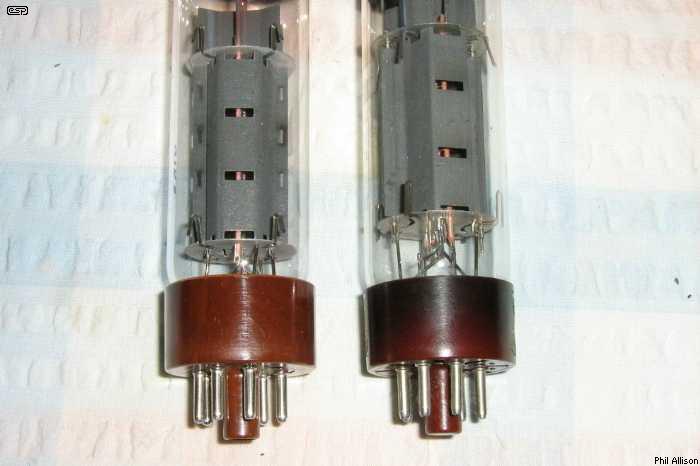
Figure 15 - Heat Affected Bakelite Valve Base
The above photo shows that the valve on the right (both are EL34s) has had its Bakelite base operating at a high temperature for an extended period, the other is new. Knowing that a hot air gun can easily cause the resistance from pin 4 to pin 5 to drop to 10 Megohms, at some lesser temperature there will still be some leakage. It doesn't need much leakage to create a problem. Different Bakelite compositions will also behave differently, and the only way to be sure there's no issue is to test a valve base.
Consider the effect if there is normally -40V grid bias voltage, and the screen grid is operating at 400V. The control grid is fed through a resistor of around 220k, and there's a total of 440V between pins 4 and 5. If the Bakelite gets hot enough so the resistance is 10 Megohms, there will be 44uA of leakage between pins 4 and 5. Since pin 5 (control grid) is effectively open circuit, all leakage current flows through the 220k grid resistor - a voltage of 9.68V across the resistor. This means that the bias voltage is now -40 + 9.68 volts, which is -30.32V. The maximum recommended continuous operating temperature for Bakelite is about 120°C. There is little useful info on the Net, but Influence of Temperature and Humidity on Bakelite Resistivity provides some details that show the trend - the graphs shown do not extend to the upper temperature limits though.
This temperature dependence can create a catastrophic situation - any leakage between pins 4 and 5 causes the valve to reduce bias voltage (make less negative) and increase plate current, making the valve run hotter, increasing the leakage, etc., etc. The end result is obvious - thermal runaway. Even at a temperature where the resistance is 40 Megohms, there's still 11uA of leakage current - enough to raise the bias voltage from -40V to -37.6V. That's easy to compensate for, by providing a little more negative bias voltage, but if the valve base gets hotter ...
This is very real and definitely does happen. It's not common to get full 'thermal runaway', but I've heard about a small number of instances. While I haven't come across it personally, the test described above was all I needed to see to realise just how easily a valve stage can be destroyed if the base is allowed to overheat. In general, all guitar amps (in particular) should be biased for the minimum acceptable current. The lower the current, the lower the heat, and there's less likelihood of a problem. Thermal runaway of this type is also known in power engineering fields, and is uncommon there too. Nevertheless, it's a real issue, and is something you need to be aware of. After an amp repair, it's a good idea to monitor the quiescent current as the amp warms up, and check it again after a full power test.
As noted above, some valve data sheets specify a maximum value for the grid (G1 - control grid) resistance, and it should not be exceeded. The allowable maximum value is usually higher for cathode bias, because it's self-correcting - at least to a degree. If there is any base leakage, more current is drawn and the cathode voltage rises, stabilising the operating point. This does not happen with fixed bias, so it's important to keep the grid resistance to the lowest value possible, and never greater than the data sheet recommendations.

Figure 16 - Resistance vs. Temperature For Bakelite
The above graph was generated based on measurements made on an EL34 (original Mullard). It's not (and is not meant to be) an absolute chart, simply representative of the characteristics of this specimen of Bakelite when heated. The maximum recommended operating temperature for Bakelite is 120°C, above which it will become discoloured and it may start to disintegrate if the temperature is considerably higher than recommended. The maximum bulb (glass) temperature for an EL34 is 250°C at the hottest point (Svetlana data sheet). Based on the above, output valves should always be operated base down (not inverted), and adequate ventilation is essential. Exactly the same applies for 6V6 and 6L6 valves in case you were wondering.
Most amplifiers (despite the dire warnings above) will never suffer from anything more than mild 'bias creep', let alone full-scale thermal runaway, but the likelihood is ever present. A change in operating conditions such as an unusually hot stage area or odd amp placement due to lack of space might just tip the balance and cause the problem to occur, and it's unlikely that anyone will ever figure out why the amp went into meltdown if they are unaware of the temperature sensitivity of Bakelite. For this reason alone, it should be obvious that mounting valves 'base up' (i.e. upside down) is not a good idea.
Another area where heat is a problem is the negative bias supply. These are often fed from a high impedance source (as shown above in the power supply), so if the electrolytic capacitors get too hot, their leakage increases and negative bias voltage is reduced (becomes less negative). A low impedance bias supply is obviously preferable, because capacitor leakage becomes unimportant. With a low impedance supply there may be more hum on the bias supply if the load increases due to a leaky capacitor, but that gives the service tech a good clue as to the fault. More importantly, the amp is unlikely to blow up because of it.
It should be pretty obvious that power valves should always be mounted with the base down so that convection doesn't cause it to get any hotter than it should. Unfortunately, many amps (especially 'combo' types) have the valves inverted, causing the bases to get much hotter than they would if mounted base down. The style of these amps is such that there's not much choice, but it's a pity that no one has ever taken this issue seriously (and most designers and service technicians will be unaware that the problem exists at all). This is one of the very few references you'll find anywhere that discusses and explains the phenomenon.
Vibration is the natural enemy of valves. The internal support structures are made from mica, and many of the electrodes (grids in particular) are very delicate. When mica is subjected to continuous vibration, it starts to disintegrate, so electrode alignment suffers and in extreme cases power valves can develop internal short circuits. Preamp valves become microphonic, because the electrodes develop tiny amounts of movement relative to each other.
The life expectancy of valves used in 'combo' amplifiers (where the amp and speaker are in the same cabinet) can be remarkably short sometimes, especially if valves are too close to the loudspeaker. The vibration can also break component leads if the parts are not tightly clamped to the PCB (if used). In many ways, it's surprising that most amps last so long without failure, but the possibility of any of these issues is always there. Fortunately, most of the parts are lightweight, so their mechanical resonance is too high to be affected by normal vibration.
There's also rough handling - valve amplifiers are not able to sustain being dropped or roughly handled for too long, and will eventually develop problems as a result. By comparison, transistor amps are almost indestructible, because they don't have any delicate bits. It's not at all uncommon for a transistor amp to work just fine, even after the case has been virtually demolished.
Where valve amps must be used (whether by preference or prejudice), a separate head and speaker is always a better choice. Vibration is reduced, but is not eliminated unless the amp head sits on a separate stand or has isolating feet, and it's easier to provide good ventilation and keep the valves mounted with the base down to avoid overheating. This implies a perfect world, where the amplifier you prefer can be obtained how you'd like it to be, but naturally things aren't that simple.
As a result, failures due to heat and/or vibration are inevitable. If the owner understands this and accepts the risk, then it may not matter that much. It's always a good idea to have valve amps serviced regularly by a competent technician so that potential failures can be avoided. There will always be unforeseen problems though ... a brand new valve can fail on the first gig due to a manufacturing defect, and no serviceman can predict random events like that. Likewise, a partially fractured component lead can escape detection, and it's generally considered impossible to anticipate a failure that doesn't show up on the bench. Even the most careful visual check can't reveal metal fatigue (other than by using industrial x-ray equipment), or a part that's about to fail but shows no symptoms.
Even output valves can become microphonic. It's not common, and will generally be heard as a rumble or rattle. Sustained low frequency oscillation is possible if the valve is particularly bad. It's not common (partly because output valves often have a fairly short life), but it can happen.
Because most power valves use a Bakelite base (as do many valve sockets), it's worth looking at some of its properties. Bakelite is a thermosetting phenol-formaldehyde resin, widely used in electrical and heat-resistant applications because of its stable thermal behavior.
Here are some of the key thermal performance properties:
Bakelite is popular because of its thermal and electrical insulation properties. Bakelite was historically (and is still) used for:
| Property | Typical Value |
| Continuous Temp | 120–160 °C |
| Short-Term Temp | 200–250 °C |
| Thermal Conductivity | 0.23–0.35 W/m·K |
| Melting Behavior | Does not melt (thermoset) |
| Flame Resistance | Self-extinguishing |
The electrical resistance of Bakelite decreases strongly with temperature, because it behaves like an insulator/semiconductor (negative temperature coefficient of resistance). For insulating polymers like Bakelite, the resistance typically follows an exponential relationship. For the following, I've assumed a valve with a plate and screen voltage of 450V (not at all uncommon, but often higher), and fixed bias of -40V. These values aren't meant to represent any particular valve, but are within normal ranges for a number of amplifiers (mainly guitar amps which have the hardest life). I used 18°C as a starting point because that was the temperature in my workshop when I ran my latest tests.
In almost all (octal) valves commonly used for guitar amps, G1 (the control grid) is on pin-5, with the screen grid on pin-4. Since the screen is always at a fairly high positive voltage and the grid is normally at a suitable negative voltage, leakage between pins 4 and 5 is not a good thing. This is where the potential problems start. To be fair, issues are fairly rare, but the potential for catastrophic failure is ever-present.
You can determine a reasonable approximation of the final resistance (at an elevated temperature) using the following procedure, assuming a resistance of 5GΩ at 18°C ...
Given:
R0 = resistance at reference temperature (18°C, 291K) = 5GΩ
RT = resistance at elevated temperature (100°C, 373K) = TBD
B = Material constant (4,000 to 8,000) = 5000 (a median value)
e = 2.718281828 (its standard value)
0°C = 273 Kelvin
Firstly, we'll determine the temperature term ...
( 1 / 373 ) - ( 1 / 291 ) = -0.000755 (-755μ)
Multiply that by B (material constant)
5,000 × -755μ = -3.77
Determine the exponential term ...
e^ -3.77 = 0.0229
Work out the final resistance ...
RT = R0 × 0.0229
RT = 5G × 0.0229 = 115MΩ (close enough)
The actual value depends on humidity (very significant for phenolic materials), the filler content, thickness and geometry. Real measurements could vary by an order of magnitude. That means that the actual resistance could be between 1.15GΩ and 11.5MΩ! My tests have shown that the probable material constant for most valve bases is around 5,000, as this aligns fairly well with my measured values. While getting the resistance to fall to a mere 11.5MΩ is theoretically possible, it's highly unlikely in a functioning amplifier. It's easy to get the resistance between pins 4 and 5 down to as little as a couple of megohms with a hot-air gun though.
With a resistance of 115MΩ you'd think that this was negligible, but if the G1 (control grid) series resistance is 220k, the bias voltage will fall from -41V to -40V. That's not a great deal, but it will still cause the valve to draw a bit more current, so it will get hotter. The Bakelite resistance will fall some more, making the grid voltage less negative again - for example it will be -38.7V with 50MΩ, assuming a G2 (screen grid) voltage of 450V (the situation is worse if the voltage is higher). Should this continue, failure is possible, so good ventilation is essential. It's not hard to get the valve base up to 100°C, especially with inverted operation!
This is the reason that the G1 series resistance must never exceed the value shown in the datasheet (it's not always given, but you may see a suggestion that the control grid [G1] should ideally be transformer driven). With a cathode-biased circuit you can ignore the valve base leakage, because this class of operation is self-correcting. However, keeping the G1 resistance as low as possible is still a good idea. This is a balancing act, because the phase-splitter must be able to drive the G1 feed resistance to the full peak-peak value needed for full power.
Designing a well behaved valve amplifier is not really difficult, but there are many things that few people seem to be aware of. This includes major manufacturers, who regularly make serious errors, correct them in the next model, then offer a 're-issue' version years later, with all the original mistakes put back into the circuit. There are very few amps that have no problems, and it's unrealistic to expect perfection. That notwithstanding, there are some design errors that simply should have been sorted out years ago, and we shouldn't be seeing them re-appear over and over again.
For the most part, preamp stages are fairly well behaved, and despite shortcuts and dubious design principles, most actually cause very little trouble. A vast number of valve amp owners seem perfectly happy with the sound quality and tone range, so I don't see many issues there. Valve failure is the biggest problem - especially with 'combo' amps, because the constant vibration damages the mica structural insulation inside the valve and allows the elements to shift slightly. The valve may then become microphonic, or develop other intermittent faults (crackling and/or farting being common complaints) that mean it must be replaced.
Poorly thought out power stages and power supplies will always be the downfall of valve guitar amps. The valves are expensive, are easily damaged by vibration, and are commonly operated outside the recommended ratings. New output valves from Asia can usually be trusted about as far as one can kick a piano, and those from Russia (etc.) are still somewhat variable. Profiteering by some distributors, fake (or faulty) 'NOS' valves on eBay and all the other scams make a valve output stage an altogether unappealing prospect in many respects. Once one looks at all the issues described above, it's actually astonishing that commercial valve guitar amps survive at all, but of course they do. However, upon close analysis we have to understand that survival is very much more a case of good luck, rather than good management. Faults and breakdowns are common, and there are plenty of people worldwide who do nothing else apart from repairing guitar amplifiers.
Looking around the Net at things that have been written about the development of valve guitar amps, one could easily get the impression that the designers knew exactly what they were doing. In reality, there is no evidence to support this - the mistakes that have been made (not once, but many times) indicate that the primary design technique was trial and error. While the comparatively simple bits like gain structure, tone controls, etc. can often only be trial and error (there is no mathematical formula for "tone"), power stages need to be engineered properly to ensure reliability. These power stages are the very ones that are so often found wanting. Excessive screen grid voltages, high impedance negative bias circuits, nothing to prevent high voltage transients that can damage valve bases, sockets and output transformers and excessive plate dissipation at full overdrive are common problems.
It should be remembered that when valve amp development was at its height, it was unthinkable that anyone would deliberately drive an amplifier into squarewave clipping. As a result, none of the revered texts (for example, the Radiotron Designer's Handbook) cover this. I am unaware of any serious work that covers this aspect of design, as it is so different from the way audio power valves were ever intended to be operated.
There is absolutely no doubt whatsoever than extremely reliable and robust valve power amps can be made if a reliable source of good quality valves can be found and maintained. The cost is another matter - few guitarists would be willing to spend the (considerable) extra money for such an amplifier. Without a 'famous' brand name on the front, I figure it might be possible to sell a small number of such amps, but it's unlikely that the development cost would be covered, let alone anyone actually making a profit over the life of the manufacturing run.
Getting reliability isn't all that hard, but it means sacrificing power for longevity. Four output valves (6L6, EL34, etc.) producing ~50W means that the valves are kept well within their ratings at all times. Plate and screen voltages can be reduced, meaning that each output valve has an easy life, as it's not being pushed beyond the published maxima for any electrode. Using quality valves (which removes most Chinese types from the equation) means that having to replace output valves regularly becomes a thing of the past. Don't expect this from any of the mainstream manufacturers though, as it costs more to build and they know that most players won't part with the extra $$ to ensure a reliable product.
Many purchasers are interested only in image, and not having the 'big name' on the front makes acceptance very hard. Others look at price, and an amp designed for high reliability is going to be expensive to make. With perhaps 90% of the market eliminated, it's going to be very hard to get a new design off the ground.
In the end, it's immaterial if your amp has the best 'tone' on the planet - if it breaks down halfway through a gig at regular intervals it's useless! Designing for reliability is (or should be) a primary concern for anyone making valve guitar amps. Sadly this does not appear to be the case, and fundamental design flaws seem to be the rule rather than the exception. Almost every valve guitar amp schematic available on the Net will show that there was something that the makers missed. Some flaws can be accepted, but others place the amp at serious risk every time it's overdriven. Bias voltage supplies are critical, and cutting corners to save a few cents is most unwise. Operating screen grids at around 500V is equally unwise, and then there's filter caps next to (hot) output valves, undersized transformers that are going to overheat - the list goes on.
I must also thank Phil Allison and John Burnett for their contributions. Phil has been particularly helpful, since he has seen every fault described - most on numerous occasions. He also alerted me to the temperature dependence of Bakelite. John's previous experience as the founder of Lenard in the 1970s (building valve guitar amps) has also been useful.
Main Index
Valves Index