

|
| Elliott Sound Products | Inverter AC Power Supplies |
 Main Index
 Articles Index
Inverters are used in all kinds of places and for all kinds of reasons. One very common application is to convert 12V from a car DC outlet to 230 or 120V AC to power small appliances. These are very common, especially with travellers with motor-homes or caravans. Another is for 'uninterruptible' backup supplies (UPS - uninterruptible power supply) for computers, either in the home or in large data centres. Inverters are also used with solar systems and wind generators, with some being very large and powerful indeed. This article only looks at the technologies commonly used for small and medium power systems - those up to a few hundred watts, but the techniques used can be scaled to almost any power level.
The basic requirements and the most common types are described. It is not meant to provide a design process, but to inform the reader what the various terms mean, how different types of inverter interact with common appliances, and how they work. There are many aspects of the design process that are far too complex to attempt to explain in detail however, so don't expect to see every possible variation described in full.
Please note that waveforms and voltages are shown based on 50Hz and 230V RMS output. 60Hz 120V systems use identical technology, and simply use a transformer with a different turns ratio and a 60Hz oscillator. DC input current is virtually unchanged for a given output power. While a 60Hz inverter can theoretically use a slightly smaller transformer than a 50Hz unit, the difference is so small that it can be ignored for all practical purposes.
Circuit examples show MOSFETs used for switching, but many high power inverters use IGBTs (insulated gate bipolar transistors) because they are more rugged and are designed for very high current operation. Some budget inverters may use standard bipolar transistors if they are only low power, because they are cheaper than the alternatives.
The idea of an inverter is simple enough. We use an oscillator to generate the required frequency (50 or 60Hz), and use that as the input to a power amplifier. Because the amplifier's working voltage is generally fairly low (typically 12 or 24V DC), a transformer is used to step up the voltage to 230V or 120V as required. Most inverters will use the transformer as part of the power amplifier itself, because this makes the overall design much simpler, especially for modified squarewave designs.
Let's assume that the circuit is 100% efficient just for the moment. This makes calculations nice and simple, and also gives us a rough idea of what the final circuit has to be able to do in real life. 12V DC is a very common input voltage, and this is suited for use in cars, motor homes and for computer UPS applications. The first thing we now need to know is how much output power do we need. For the sake of the exercise, let's assume 1,000W (1kW).
To obtain 1kW at 120V requires an output current of 8.33A, or 4.35A at 230V. Unfortunately, 1kW at 12V means that we need 83.33A from the battery, ignoring all losses. If you wanted to be able to provide 1kW for 1 hour, you'll quickly discover that you need a 12V battery rated at around 120AH (amp hours). Lead-acid batteries are the most economical choice for a UPS, and that's what you already have in the car (make sure that you don't fully discharge the battery). Lead-acid batteries (including gel-cell and AGM types) provide a reduced capacity if they are discharged quickly. For example, a 120AH battery will usually only provide its claimed capacity if discharged at the 10 hour rate (i.e. 10 hours at a current of 12A for a 120AH battery). Higher discharge current means that the capacity of the battery is reduced.
The above current requirements refer only to the RMS output current (AC), and the average input current (DC). For 230V output from a 12V source, the average DC input is typically around 20 times the RMS output current for a modified squarewave inverter. DC input current is higher than the rough calculation, because it must include an allowance for losses in the system. In reality it is wise to lower your expectations.
It's probably fair to say that inverters are a fairly evil load for any battery, especially if you expect more than a few watts output. It's equally fair to say that the output of any inverter that isn't a sinewave ('pure' sinewave) is also a pretty evil source for a great many loads. It's not even possible to give a list, because so many loads are now electronically controlled. Once electronics is involved with a load (especially motors and transformers), it's only possible to know what's involved if you have detailed specifications and/or a circuit diagram.
Some products might state whether they are suitable for use with various inverters, but most don't. Most switchmode power supplies will be happy enough, but they may be subjected to higher peak current than normal if the input is not a sinewave. PCs should be alright - they are the very load that most UPS systems are designed for. If in doubt, seek advice from the appliance manufacturer.
Inverters are commonly classified by their output waveform, so you will typically see the following types offered ...
Note that 'modified sinewave' and 'modified squarewave' inverters are actually quite different, but it's common for the two to be lumped together and the terms used interchangeably. This is partly because there is no strict definition of the terms, and advertising material is notorious for bending the rules to make a product seem more appealing. Claiming that an inverter is modified sinewave sounds much better than saying it's modified squarewave - particularly for people who have a little knowledge of such things. The three most common types have their waveforms shown below. In each case the RMS value of the voltage waveform is 230V, but only the modified squarewave and sinewave types maintain the correct peak voltage of 325V.

Figure 1 - Inverter Waveforms, All 50Hz, 230V RMS
For the squarewave and modified squarewave waveforms, I added the sinewave as an overlay so you can see the difference clearly. The 'modified sinewave' waveform isn't shown here because it's somewhat more complex and harder to produce. There are also several different ways to create a modified sinewave, and these are discussed below. As noted above, in many advertisements you will see the modified squarewave type referred to as modified sinewave. This is false advertising, but some people really don't know the difference.
All squarewave based inverters will cause stress to interference suppression components fitted to the connected appliance. A sinewave has a relatively gentle rate of change of voltage (DVDT aka ΔVΔT, the change of voltage over time). Squarewaves (modified or otherwise) have a very high DVDT, and additional filtering is needed on the inverter output to reduce it to something acceptable to the most common loads.
Filtering is also needed so that products will pass EMI (electromagnetic interference) tests that apply in most countries. It's not at all uncommon for inverters to cause radio interference, especially on the AM bands. You can also expect to be told that this interference will cause cancer, your belly-button will fall off and you'll get ingrown toenails as a result of 'dirty electricity' as it's become known. Maybe bad things will happen, but it's not like we use inverters pressed close to our bodies all day. Most 'pure' sinewave inverters also create interference because they operate at high switching frequencies.
The simplest inverter is a squarewave type. The oscillator is very basic, and they are fairly easy to build. Unfortunately, the ratio of peak to RMS voltage is very different from a sinewave, and this will cause stress to some appliances. Motors and transformers in particular will usually draw much higher current than they are designed for, so they may run hot enough to cause premature failure. Most switchmode power supplies don't care, and will operate quite happily from a squarewave input. Interference suppression capacitors will be stressed by the fast rise time of the squarewave.
A sinewave has a peak to RMS ratio of 1.414 (√2), so a 230V sinewave has a peak value of 325V and a 120V sinewave has a peak of 170V (close enough in each case). A squarewave with a peak value of 325V has an RMS voltage of ... 325V. Peak and RMS are the same. If the voltage is reduced so that the RMS voltage is correct, then many electronic power supplies will see a greatly reduced input voltage because many charge filter capacitors to the peak of the voltage. So where the load expects to see peaks of 325V (or 170V), it will only get 230V or 120V peaks. Some loads will not power up properly if the voltage is too low.
The above notwithstanding, I will explain a basic squarewave inverter first, because the same switching circuitry is used for the modified squarewave converter as well. The simple squarewave is easy to understand, and will make it easier to follow the more complex options. The most common arrangement for simple inverters is to use a transformer with a centre-tapped low-voltage primary. The centre tap is connected to the 12V DC supply, and each end of the winding is connected to earth/ ground in turn. This is shown in Figure 2. It is important to understand that there must be no time when both MOSFETs of transistors are turned on at the same time, so there is a short period where both are turned off. This is known as 'dead time'.
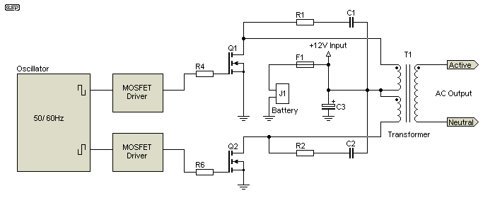
Figure 2 - Basic Squarewave Inverter
The inverter shown in Figure 2 is very basic - it has been simplified to such an extent that it is easy to understand, but it does not work very well. The biggest problem is mentioned above - the peak and RMS voltages are the same, and this limits its usefulness. However, the same basic circuit operated at a higher frequency (25kHz or more) is exactly what's used with a great many DC-DC converters. See Project 89 as an example. R1/C1 and R2/C2 are snubber circuits that reduce high voltage spikes from the transformer.
Even operated at 50Hz, the circuit is fairly efficient. It's very important to choose transistors or MOSFETs that have a very low 'on' resistance. It is imperative that losses in the switching devices are minimised, and heavy wire is needed for all interconnections and on the transformer's primary. Every small resistances add up quite quickly in a high current circuit, and it's easy for losses to become so great that overall efficiency is reduced dramatically. This is not what you want when operating equipment from a battery, because amp-hours cost money.
As shown, the output stage is very similar to that used in a great many different inverters. The only difference between the circuit shown and a modified squarewave inverter is the oscillator and the transformer voltage ratio. For the squarewave inverter, the transformer ratio is determined by ...
Rt = Vout / Vin (Where Rt is the transformation ratio, Vin is the input voltage and Vout is the RMS output voltage... equal to the peak voltage with a squarewave inverter)
Rt = 230 / 12 = 1:19.16
The above does not make any allowance for losses, and the ratio would need to be between 1:20 and 1:22 (for each primary winding) to allow for losses across the MOSFETs and in the transformer windings. This type of inverter has no mechanism for regulation, so the output voltage will vary with the load. To keep the variation to a minimum, all losses must be kept as low as possible.
An AC waveform swings positive and negative, so the peak-to-peak voltage is double the peak voltage. This is accomplished by the transformer, which has a dual primary with a centre-tap. Because of the dual primary, the ratio may also be written as 1+1:20 (for example). The ratio based on the voltage across the entire primary is 1:10 and the peak-to-peak input voltage is actually 24V. This is the voltage across each switching MOSFET - it varies between close to zero and +24V. This is simple transformer theory - if you don't understand, then please read the articles Transformers, Part 1 and Transformers, Part 2.
To provide a waveform that has the same RMS and peak voltages as the mains, we need to modify the waveform to that shown in Figure 1B. The remainder of the circuit remains exactly the same, but the transformer ratio is changed so that the peak voltage is created.
Rt = Vpeak / Vin
Rt = 325 / 12 = 1:27.08
Again, allowances must be made for switching and transformer winding resistance, so the final ratio will be around 1:30 to obtain the required 325V peak voltage for a 230V RMS voltage under load. A lot of common loads rely on the peak voltage, in particular simple switchmode power supplies. Unfortunately, it's not feasible to regulate the peak voltage with a basic design, but it is relatively easy to regulate the RMS voltage simply by changing the width of the voltage pulses. As the pulse width is increased, the RMS voltage is increased, even though the peak voltage may be reduced.
For a waveform with exactly 325V peaks, each positive and negative going pulse needs to be exactly 5ms wide. This means that for a 50Hz waveform (20ms for one complete cycle) the voltage will be as shown in Figure 3. This is the same waveform as that shown in Figure 1B, but expanded for clarity.
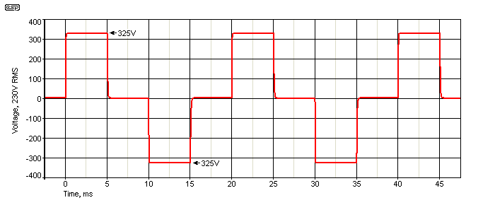
Figure 3 - Modified Squarewave Waveform In Detail
Naturally, for 60Hz mains the timing is different, but the essential part is that the waveform period is divided evenly into 4 discrete segments that are exactly equal. For 50Hz, the period is 20ms, so the waveform is made up of 4 × 5ms segments. It might not be immediately apparent, but this gives the same 1.414 peak/ RMS value as a sinewave. The RMS value is 230V and the peak is 325V (give or take a fraction of a volt). The distortion is a rather high 47% (THD), and although it can be reduced by changing the width of the pulses, doing so changes the voltage. The best distortion figure (28% THD) is achieved when the pulses are about 7ms wide (instead of 5ms), but the RMS voltage is increased to over 270V. All in all, equally timed pulses and dead time are far simpler to generate and give a fairly good overall result.
The transformer requires a different turns ratio as described above. Apart from the oscillator, the inverter circuit is identical to that shown in Figure 2. The oscillator must be more complex to produce the waveform, but it's not difficult and can be done in many different ways. One of the easiest is to use a PIC (or any other programmable micro-controller), which also means that frequency stability can be extremely good if the controller uses a crystal oscillator.
Regulation of the RMS voltage can be achieved by making the voltage pulses wider or narrower, but the peak voltage cannot be regulated without extreme circuit complexity. For a simple inverter that's suitable for many common loads, the additional circuitry will never be added because the circuit would not be simple any more.
Since it is easy to regulate the RMS value by simply changing the width of the pulses, you may think of this as a very (very!) crude form of PWM (pulse width modulation). And so it is. It is theoretically possible to add a filter that will give a passable sinewave at the output, but because the frequency is so low it would be uneconomical and would actually create far more problems than it would ever solve.
While the modified squarewave inverter can be seen as a very crude form of PWM, one form of modified sinewave uses low speed PWM to achieve a rough approximation to a sinewave (discussed below). Another variation is to build a step waveform, by switching different transformer windings in and out of circuit. This is shown below, and you can see that it is starting to resemble a rather piecemeal sinewave. This is a crude form of pulse amplitude modulation (PAM), a technique that was common for a brief period before fully digital systems were economically feasible.
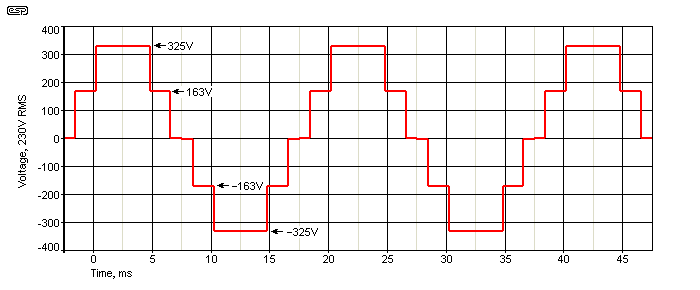
Figure 4 - Modified Sinewave Waveform
This waveform cannot be created using the simple switching shown above, and requires a transformer with more primary windings to generate the output voltage. By carefully adjusting the number of turns and switch timing it's possible to get a waveform with distortion of around 20% or better. Because of the relative complexity of the waveform, it has to be created using discrete logic (cheap but inflexible) or a programmable microcontroller (PIC or similar), which allows fine timing adjustments if necessary.
This type of inverter is not common, because its transformer is more complex and it needs additional switching transistors and driver circuits. With Class-D amplifier technology now commonplace, it's easier and cheaper to build a 'true' sinewave inverter than to mess around trying to implement a workable modified sinewave. To give you an idea of the relative complexity, Figure 5 shows a simplified circuit.
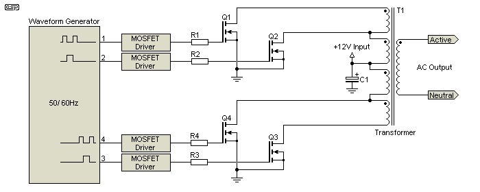
Figure 5 - Simplified Modified Sinewave Schematic
It's no longer appropriate to call the frequency generator an oscillator, because it has to generate a relatively complex waveform. This make it a waveform generator, rather than a simple oscillator. It may not be immediately apparent how this circuit works, so first let's assume that we are about to generate a positive half cycle followed by a negative half cycle.
It is imperative that no two MOSFETs are ever on at the same time, or extremely high and possibly destructive current will flow. This means that there will be small glitches in the output waveform, but most loads will be unaffected. Some basic filtering will remove the highest harmonic frequencies, and is essential to prevent radio frequency interference. Snubber circuits have not been shown, nor has the fuse.
The waveform timings described are only intended as an example. To optimise the peak to RMS ratio and distortion performance it will be necessary to make small adjustments to the timing of each pulse and off period. This will also be necessary to change the frequency - the timing of the pulses described will provide a 50Hz output. Changes to the transformer winding ratios and small timing modifications can be done to optimise the peak vs. RMS voltage and output distortion. It should be possible to get distortion below 20% with a peak to RMS ratio very close to 1.414:1 with this arrangement.
There is another variant of the 'modified sinewave' inverter that uses low-speed pulse width modulation (PWM). Rather than use a switching frequency of 25kHz or so, it can be done with a frequency of around 550Hz. The 'sampling' frequency should be an odd harmonic of the desired fundamental frequency to ensure a symmetrical output waveform.

Figure 6 - Low-Speed Pulse Width Modulation Waveform
There is very little point trying to filter this waveform, because the sampling frequency is far too low and no sensible filter can remove the harmonics. I have no personal experience with this type of inverter, so I can't be certain how most common loads will behave. Because of the very high harmonic content, most motors and transformers are likely to be stressed and may overheat. With 96% harmonic distortion, it's by far the worst so far, and if you are going to go to the trouble of PWM, then it might as well be the real thing from the outset. Like the other 'modified sinewave' variant shown above, it will cost so little more to implement a true sinewave that low-speed PWM is not worth considering.
Making a pure sinewave inverter is (in theory) not especially difficult. All you need is a sinewave oscillator of the right frequency, a power amplifier to provide the current you need, and a transformer to increase the voltage to 230V or 120V RMS. Unfortunately, this is very inefficient and makes poor use of the battery's capacity. This used to be fairly common for sinewave laboratory power supplies, and I have one in my workshop. It's very large, extremely heavy (two very large transformers and a big heatsink), and although the waveform is extremely good it runs hot enough at full load to make full use of the heavy-duty fans that are fitted. Forget battery operation entirely, because it operates from relatively high voltage to keep the current within sensible limits. This power supply (it's inappropriate to call it an inverter) uses a vast number of power transistors to allow it to drive 'difficult' loads.
Although it is possible to use much the same power amplifier arrangement as shown in Figure 2, a great deal of feedback is needed to obtain good linearity. It's generally easier to use a more-or-less conventional power amp (but remembering that it has to be fully protected against accidental shorts, normal momentary overloads and possibly very reactive loads. This makes the amplifier complex and expensive, and more so if you want to operate if from a low supply voltage.
When the supply voltage is only 12V DC, it's almost essential to run two amplifiers in bridge (BTL) mode, since that effectively doubles the supply voltage. Using a linear power amplifier is not viable for an inverter for a UPS, because the efficiency is poor (expect no better than ~60% for 'real-world' circuits), although it can be increased slightly at the expense of some distortion. Expecting better than 70% overall efficiency is generally unrealistic unless the sinewave is clipped to the extent that it resembles a squarewave.
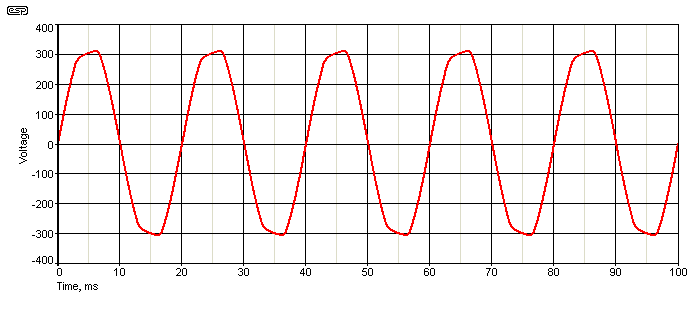
Figure 7 - Clipped 'Pure' Sinewave Waveform
With distortion of just over 5% (the mains can be worse than that), an RMS voltage of 231.5V and a peak value of 310V, the above waveform is very close to that obtained directly from the mains. Because of the clipping, the efficiency will be in the vicinity of 70-75% - somewhat better than the theoretical maximum with a pure sinewave. The transistors still need substantial heatsinks, and of course every Watt of heat has to be supplied by the battery.
As should be apparent, this is not an ideal circuit. The relatively low distortion is good for motors and other inductive loads, and causes little stress to any load because it's close to what comes out of a wall outlet. However the extra battery drain is high enough that you lose at least 30% of the battery's capacity in heat.
Because this is not a viable option, no representative circuit is provided. If anyone wanted to build an inverter using linear amplifiers, it is feasible and potentially useful if the power levels are low. One example that comes to mind is to use a crystal-controlled sinewave oscillator, IC power amplifier and a suitable transformer to create up to 10W or so. Such an arrangement is ideal for driving synchronous clocks or turntable motors that generally only use 2-3W at the most. Ensuring that the amplifier does clip will help to reduce the total power dissipation.
PWM is the technology of choice for maximum efficiency and a clean sinewave output. The modulation frequency should be high enough to ensure no-one can hear it, which typically means at least 25kHz. Lower frequencies can be used, but the noise from the transformer or filter inductor may be intolerable and the filter components will be larger and more expensive. There are countless chip-sets available for making PWM circuits, and it's not difficult to get very high performance with high efficiency. It's possible to get a properly designed Class-D amplifier to have an efficiency of between 80% and 90%, but there will also be transformer losses that must be considered.
For power output of more than perhaps 200W, the Class-D amplifier will almost certainly use discrete components. IC amplifiers are available that can do more, but an inverter is a special case when it comes to the load. Many common loads will present close to a short-circuit when first powered on (motors, toroidal transformers and simple mains rectifier-filter capacitor power supplies for example), and this causes extreme stress on the amplifier.
For an output of 500W (for example) at 230V, the load impedance is 106 ohms. Since the transformer will need a 1:30 ratio (1:900 impedance ratio), the effective load on the power amplifier is only 118mΩ - 0.118 ohm! This is an extraordinarily low impedance, and gives you an idea of the kind of load experienced. Remember that this can drop to almost zero, limited only by the resistance of the transformer windings, and so far has only considered a resistive load. There's more info on the transformer ratios below. To combat the high losses experienced at such low impedances, it's wise (and more efficient) to include a boost converter to increase the available 12V to something more manageable. Naturally, there will be losses involved in the boost converter, but with careful design they will be less than the losses incurred without it.
To examine the processes needed for a Class-D power amp for inverters, I suggest that you read the Texas Instruments application note [ 2 ]. This recommends the use of a 'tri-level' PWM waveform, generated by dedicated logic and uses a bridged output stage. A highly simplified explanation is shown here as well, and I expect that it will be somewhat easier to understand. It's also worth looking at the Class-D article on the ESP website [ 3 ].
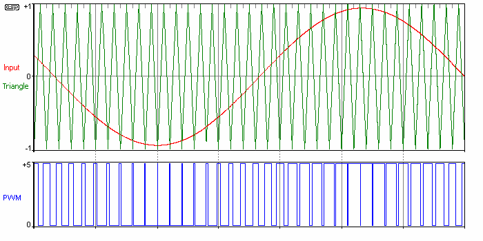
Figure 8 - Derivation Of PWM (Blue) From Input (Red) And Reference (Green)
Generating the PWM waveform is (at least in theory) delightfully simple. A sinewave is fed into one input of a comparator, and a linear triangle waveform into the other. When the signal voltage is greater than the reference, the output of the comparator is high and vice versa. The comparator output will look like the blue trace in Figure 8. Being a simple on/off waveform, it's easy to amplify and the original sinewave can be reconstructed using a relatively simple inductor/capacitor (LC) filter. Naturally, reality is different. Dedicated chipsets that are available to generate PWM signals will generally give far better results than discrete ICs, and will provide much of the other support functions as well. These include MOSFET gate drivers and cycle-by-cycle current limiting, both essential for an inverter expected to deliver significant current.
The essential functions are shown below, but without including a full schematic. Figure 9 is highly simplified, because a complete schematic is too complex to follow easily. The two oscillators are shown in the next section - one 50Hz sinewave oscillator and one 25kHz triangle wave oscillator. These are used to generate the PWM waveform. Note that in switchmode power supply language, a bridged output stage like that shown below is commonly referred to as an 'H' bridge, and is drawn so that the switching devices and transformer form the shape of the letter 'H'.
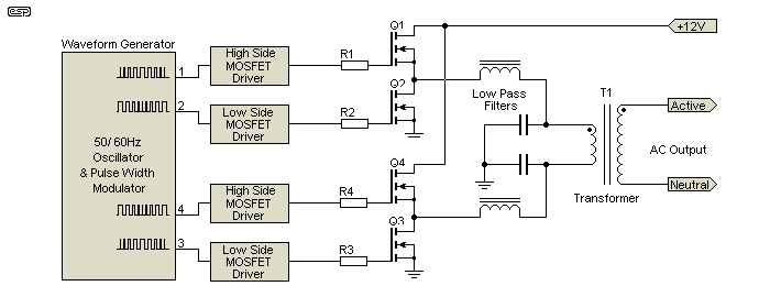
Figure 9 - Simplified PWM Sinewave Inverter
As shown above, it is preferable to use a bridged amplifier to drive the primary. This has the effect of doubling the supply voltage, so the maximum swing across the transformer is almost 8.5V RMS (24V peak-peak) rather than just under 4.25V that can be obtained from a single 12V supply. The current that each MOSFET stage must control is extremely high, and MOSFETs with extremely low RDSon (on resistance) are needed. At an output of just 1A peak into the load, each MOSFET will be switching a peak current of at least 30A DC.
The bridged PWM amplifiers are driven just like any other bridged amp, but with a PWM signal. Because the high frequency switching may play havoc with a transformer attached, it might necessary to use the output low pass filters so that the switching signal is isolated from the transformer. If the transformer is made to have very low leakage inductance, it will be possible to place the low pass filter at the output, but this means that the required inductance will be greater than that needed if the filter is in the low voltage circuit. The MOSFET driver sections are responsible for level shifting (high side) and for providing the required dead-time to ensure that the vertical MOSFET pairs (Q1, Q2 and Q3, Q4) are never on at the same time.
For any high power inverter, the transformer becomes a major part of the unit, in size, weight and cost. If the inverter uses a switchmode boost supply to obtain the peak voltage needed for the output, it can use a much smaller transformer because it will switch at 25kHz or more, rather than 50Hz. The output stage then works with the full peak voltage, either 325V or 170V DC, to suit 230V and 120V mains respectively. A basic diagram of this kind of inverter is shown below. By using a higher DC voltage (e.g. 400V for 230V output), it becomes possible to provide regulation that can be as good as you need it to be.
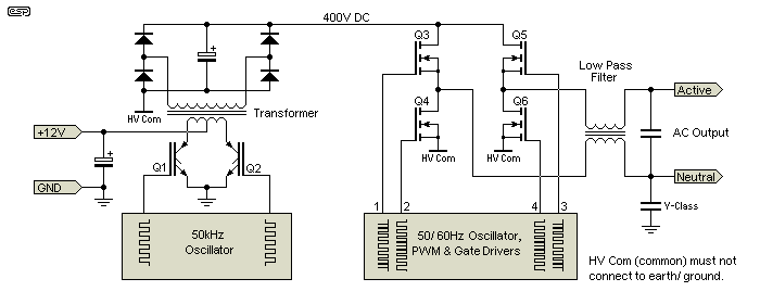
Figure 10 - DC-DC Converter, High Voltage PWM
This arrangement allows the DC-DC converter to be optimised, and the transformer can be a great deal smaller than would otherwise be the case. Although only two IGBTs are shown for the DC-DC converter, ideally it would use several high current devices in parallel so that the extremely high current can be handled with minimum losses. Since this arrangement may be used with inverters of any power, but it only becomes economical for an output of perhaps 250VA or more (typically allowing for a 500VA peak or 'surge' rating). At an output of just 500VA (or 500W), the average DC current will be around 47A allowing for losses.
The output stage will be an 'H' bridge so that the DC voltage is only half that otherwise needed for a full AC cycle. It may seem silly to use two separate stages, having a DC-DC converter followed by a PWM sinewave generator at the full mains voltage, but it has many advantages and if done properly will be more efficient than a single switching stage. This approach also makes regulation easier, but it requires very comprehensive protective circuits around the output switching devices (not shown in Figure 10).
Providing protection isn't especially difficult, but it needs to be fast enough to protect the switching devices under worst case conditions. Mains loads can be very hard on inverters, because there are so many that appear to be close to a short circuit when power is applied. Most switchmode power supplies, large transformers and motors are especially difficult, with motors being one of the hardest of all. Start current for typical motors is very high, and if the motor has to start under load (refrigeration compressors being one of the worst offenders) the problem is greater still. If the inverter can't supply enough current for the motor to start, either the inverter or the motor (or both) may be damaged.
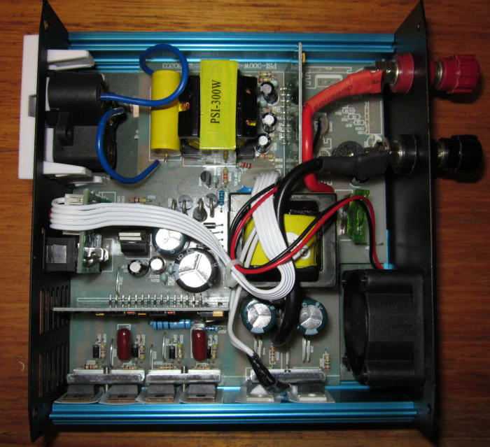
Figure 11 - Photo Of 300W High Voltage PWM Inverter
The photo above shows the insides of a 300W inverter that follows the block diagram shown in Figure 10 pretty much exactly. The output section is driven by a PIC microcontroller and two IR2110 combined high-side and low-side MOSFET drivers, each driving a pair of IRF840 high voltage MOSFETs. The PIC is responsible for generating the sinewave, probably using a simple table to determine the pulse width needed for each transition. It's crystal controlled, so the frequency will be fairly accurate, but this wasn't tested. Distortion is very low - all harmonics are below -40dB, so total distortion is unlikely to exceed around 2% - this is an excellent result for an inverter.
The main inverter section uses a pair of IGBTs to handle the high current. The large yellow core marked PSI-300W is the inductor for the output filter, along with a 2uF, 300V AC capacitor. The other core you can see is the switching transformer that converts the 12V input to approximately 350V DC, switching at ~40kHz.
There are many different ways to make oscillators that are suitable for generating sinewaves and triangle waves. In a highly integrated commercial design, they will probably both be digital, and preferably crystal locked so the frequency is accurate. For a UPS, the situation is complicated if you want the output of the generator to be in phase with the mains so the changeover is free of glitches. In the case of a stand-alone sinewave generator, we don't care, especially as the system can also operate as a frequency changer. Producing 60Hz mains in a 50Hz country (or vice versa) is a fairly common testing laboratory requirement for example.
The oscillator described in the first reference [ 1 ] and shown in Figure 10 is fairly straightforward, and has good frequency stability. Amplitude stability is determined by the saturation voltage of the first opamp, and may vary slightly with temperature. For a more comprehensive look at various sinewave generator techniques, see Sinewave Oscillators - Characteristics, Topologies and Examples. For an AC source, distortion below 1% is more than acceptable, and even a Class-D stage can benefit (slightly) by allowing it to clip the peaks. For most applications it doesn't matter at all if the generated mains waveform has up to 5% total distortion, and this eases the demands on the 50/60Hz oscillator. In particular, it means that accurate amplitude stabilisation techniques aren't needed, simplifying the design.

Figure 12 - Three Stage Phase-Shift Sinewave Oscillator
While the design is straightforward and has fairly low distortion, the amplitude will vary a little as the frequency is changed via VR1. The amplitude can be varied to some extent by changing the ratio of R3 and R4, but this also changes the frequency and is not useful. U1 operates as a amplifier with gain controlled by R3 and R4. As shown it has a gain of 10 (100k / 10k), and if the gain is reduced by much it won't oscillate. Higher gain makes oscillation a certainty, but at the expense of higher distortion. With a 12V supply, the output level is about 460mV RMS with a distortion of 0.8%. Frequency is 50Hz with VR1 set to 52k. Because the output sinewave is taken from the output of an opamp, it has low impedance. To obtain a higher level, U4 can be wired as an amplifier, or the output can taken from U3 (930mV with 2% distortion).
This oscillator is usable for either linear or Class-D inverters. There's obviously not much point making a sinewave oscillator for a modified squarewave inverter. A good sinewave can also be created using digital synthesis, and that has the advantage that it can be crystal controlled. While absolute frequency stability is usually not very important for an inverter, it doesn't hurt anything and if it comes (virtually) free then what's not to like? A PIC can be used to generate the sinewave, and also monitor circuit performance, temperature, etc.
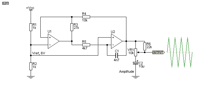
Figure 13 - Schmitt Trigger + Integrator Triangle Generator
The triangle wave generator can also be done many different ways, but as shown above is fairly simple and has good linearity. U1 is wired as a Schmitt trigger, having positive feedback applied to its non-inverting input. U2 is an integrator. The output from U2 increases until the non-inverting input of U1 is forced higher than the reference voltage (Vref) at the inverting input. It rapidly switches its output high, causing the output of U2 to fall linearly until the non-inverting input of U1 is forced lower than Vref. The cycle repeats indefinitely. With the values shown and a 12V supply, the output amplitude is 4V peak-to-peak at a frequency of 25.8kHz. VR1 allows you to set the level to match that from the sinewave generator for the optimum modulation level. C2 is used at the 'bottom' end of VR1 so that the 6V reference voltage is retained, and doesn't vary with the pot setting. R6 ensures that the triangle wave and DC reference level cannot be lost, even if the pot becomes open-circuit.
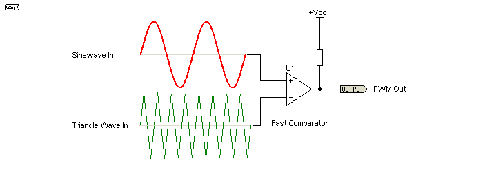
Figure 14 - Comparator To Create PWM Waveform
By combining the circuits of Figure 12 and Figure 13 and adding a comparator, we get a complete pulse width modulator - and yes, it really is that simple. For a better idea of the exact waveforms involved, refer to Figure 8. The output is PWM, and is ready to send to the switching MOSFETs via a suitable level shifter and gate driver IC. These are readily available, with the International Rectifier IR2110 being one of the most common. This part is specifically designed to drive the gates of MOSFETs for Class-D amplifiers.
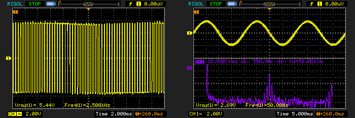
Figure 15 (Left) - PWM Waveform, 2.5kHz with 50Hz Modulation
Figure 16 (Right) - Recovered 50Hz Signal With Spectrum
Figure 15 shows the output of a pulse width modulator along the lines of that shown in Figure 14. The main difference is that I used an opamp (which works but is isn't really fast enough), and I had to reduce the triangle waveform frequency to 2.5kHz so the waveform could be seen properly on the oscilloscope.
The recovered waveform is shown in Figure 16, along with the frequency spectrum in the lower violet trace. The 50Hz waveform is the spike at the extreme left, and the 2.5kHz residual (with its sidebands) is seen in the centre of the frequency domain measurement. The filter used was just a simple resistor-capacitor low-pass type with a -3dB frequency of 159Hz (10k resistor and 100nF capacitor), so there's more of the 2.5kHz signal than you'd normally see. If the modulation carrier frequency is increased to 25kHz, the 50Hz waveform is very clean indeed - even with such a crude filter and slow opamp.
Many inverters offer 'regulation', but it's often not proper regulation that maintains both peak and RMS at the designated output voltage. For modified squarewave inverters, the regulation circuit will attempt to maintain the RMS voltage as the peak sags under load and/or as the battery discharges. This is done by making the 'on' periods longer, and the output voltage starts to resemble that from a squarewave inverter as the load is increased.
True sinewave inverters using PWM will use a variety of techniques, but the easiest is simply to allow the output waveform to clip. The alternative is to ensure that the PWM amplifier has some headroom, and to apply a comprehensive feedback circuit to ensure that the AC output remains within preset limits.
With all inverters, it is essential to realise that the current on the input side will be very high. That means that everything in the chain can affect the regulation, from the battery, supply leads, switching devices and transformer primary windings. Even a rather paltry 100W inverter will draw 8.33A DC at 12V, but the instantaneous current is higher and losses haven't been considered. The actual (average) current will be closer to 10A, and peak current will be almost 20A. Even a small resistance causes a serious voltage drop - for example just 0.1 ohm will cause a loss of 2V at 20A, so 12V is now only 10V.
It is quite obvious that if 12V is reduced to 10V at the peak current, then the output voltage must fall at least in proportion, and there may be a bit more loss due to internal resistances. The required peak of 325V will fall to only 270V and the RMS value will be down to about 190V. The only way that proper output regulation can be achieved is with feedback. A high voltage PWM inverter is likely to be the only one that can offer both acceptable regulation (better than 5% from no load to full load) while maintaining the correct peak to RMS ratio - see below.
The transformer used for a low frequency inverter is invariably a step-up type. The primary must have very low resistance because of the high current involved, and in all cases the transformer has to be designed for the mains frequency in use. This means that it will be comparatively large - at least the same size as a normal step-down transformer intended for the same VA rating.
Depending on the intended usage (intermittent or permanently connected for example) the allowable losses will be different. A transformer that will only be used for occasional UPS duties may be smaller than the ideal case, and it will therefore be cheaper, smaller and lighter. Of course, it will also have higher losses. The primary inductance is of little real consequence, but it must be high enough to ensure that magnetising current at 50 or 60Hz is low enough to ensure losses are within sensible limits. Inductance calculations of mains transformers is not an exact science. Much of the magnetising current will be due to partial saturation, so the calculated value will be lower than expected.
As an example, a fairly basic (i.e. nothing special) 30:1 ratio (230 to 7.67V RMS) mains voltage transformer may draw 50mA from a 230V 50Hz mains supply with no load. This is the magnetising current, and the effective inductance is therefore calculated using the normal inductive reactance formula ...
XL = V / I
XL = 230 / 0.05 = 4.6k ohms
L = XL / ( 2π × f )
L = 4.6k / ( 6.283 × 50 ) = 14.64H
It follows that with a turns ratio is 30:1 (7.66V RMS Output) the effective secondary inductance will be about 16.2mH. When used in reverse for an inverter, the best case magnetising current will be 1.5A, but it will usually be more and will vary widely depending on the transformer's construction. As always with transformer design, it's really only the core saturation limit that needs to be addressed, and this depends on the core material, the type of core (E-I, toroidal, etc.) and the maximum allowable dissipation at idle. Contrary to popular belief, the core flux of any transformer is at a maximum when there is no load. The flux always reduces as the load current is increased [ 5 ].
For a step-up transformer, it is essential that the low voltage primary has enough turns to prevent core saturation. It's a much bigger problem with step-up transformers because the primary resistance is very low, and even slight saturation will cause a dramatic increase in the current drawn from the battery. Unlike a conventional mains transformer, the primary resistance is too low to provide any current limiting. You will have noted that I suggested a secondary voltage of only 7.67V (10.8V peak), and this is necessary because the transformer will be used in reverse, and there is only a 12V supply available. Expecting at least 1.2V loss is realistic for a small inverter, although it may be greater.
As always, transformer design is a compromise, and to get the lowest resistance means few turns of thick wire. However, if the wire is so thick that you can't get enough turns, the core will saturate and no-load losses become excessive. The designer's task is to work out the thickest wire possible for the turns needed, and to choose a core that's big enough to avoid saturation, but not so big that it becomes too heavy and expensive.
Perhaps surprisingly, even if the amplifier is PWM at high frequency, the transformer can't be a small ferrite core type. The low frequency content (i.e. the mains frequency) is the dominant factor, and the transformer has to be able to handle that, not the switching frequency. This limitation applies even if there is no low pass filter between the amplifier(s) and the transformer's low voltage primary.
Naturally, this is not the case where the PWM is done at high voltage and the PWM stage supplies the AC output directly. In HV PWM inverters, the high voltage is generated by a high frequency switchmode supply, and that can use a much smaller transformer core because it operates at 25kHz or more. Most of these inverters are fan cooled, even when only they are fairly low output power types (100-200W or so).
It's not at all uncommon for commercially available (low voltage, step up transformer) inverters to have a transformer that is clearly too small. In order to get the required number of turns needed to avoid saturation, the transformer must use wire that is thinner than required to remain cool under load. This is usually addressed by fan cooling the transformer. Although this certainly works and prevents the transformer from melt-down, it doesn't prevent the losses that cause the transformer to get hot in the first place. The result is decreased efficiency.
As should now be obvious, an inverter is not trivial. Many of the cheap ones that are available are only low power, and if they claim to be more than around 100VA then you can be assured that they won't be the size of a drink can. Remember that the transformer alone will be rated for the full load current, so even a small inverter (100VA, or 230V at 430mA) needs a transformer rated for at least 100VA. Most will make claims of up to double the rated output for 'surge' or 'peak' output, but this will almost invariably mean that the transformer is overloaded during this period. A common method to allow a smaller than ideal transformer is to fan cool it, and this is quite common for cheap inverters.
Frequency accuracy and stability are rarely quoted. Although relatively unimportant for most applications (5% accuracy will usually be quite sufficient) there are a few cases where both stability and frequency are extremely important. Don't imagine that any budget inverter is stable enough to drive synchronous clock or timer motors for example. An error that's insignificant for most applications is extremely significant for clocks and mechanical timers that use the mains as a reference frequency.
In case anyone was wondering, there is no project for a sinewave inverter and there's not about to be. On-line auction sites will have many listings for inverters, some will be modified squarewave (but claim 'modified sinewave'), and others shown as true sinewave. This may or may not be the truth. Either way, at the prices they sell for, it's not worth trying to build one. In general, I'd suggest that you halve the claimed rating, as I suspect that very few are capable of their advertised power ratings, but even after doing that, they are still cheap.
Because of the very high currents involved, the switching devices must be extremely rugged, and good protection is needed to ensure that momentary overloads don't cause failure. It is also necessary to include battery protection, so that if the voltage falls below a pre-determined minimum voltage the inverter turns off. If this isn't included, the battery will be ruined because all current chemistries are damaged if they are discharged too far. As a guide, you can assume about 10A for each 100W of output with a 12V input. This assumes an overall efficiency of around 83%, which will cover most budget inverters and quite a few up-market types as well.
For those so inclined, it can be amusing to look through some of the advertisements for inverters. I've seen (claimed) 2,500W (5,000W peak) inverters, where it's stated that the unit has a 40A fuse. With a 12V supply, the inverter can be expected to draw up to 500A (peak) and around 250A at full rated continuous power (at 12V input and allowing for losses) *. I wonder what the 40A DC fuse is for. Perhaps they are telling naughty fibs. 
* 40A at 12V is 480W input power, and does not allow for losses. Actual output would be around 460W assuming 'typical' losses in the circuitry. At 13.8V (battery under charge) 40A is 552W input power, nowhere near 2,500W.


 Main Index
 Articles Index