
|
|
| Elliott Sound Products | Project 89 |
This contributed project is a result of considerable collaboration between Sergio and myself, and should not be seen as necessarily a complete project in itself, but a stepping stone to understanding switching power supplies, how they work, and what you can do with them.
Be warned - there is considerable risk. Because of the extremely high current available from a car battery, a tiny mistake may easily lead to catastrophic failure. All electronic components are said to contain smoke (wire contains an enormous amount), and a slip of the soldering iron can liberate an unbelievable quantity. Seriously though, the risk of severe burns and the possibility of causing a fire in your car are very real, and should not be underestimated. 300A from a car battery can do a vast amount of damage in a few milliseconds - should the fuse not blow (you will use a fuse, won't you?), then the damage can be extensive.
At various points in Sergio's part of the article, I have included some additional information.
Please see the special note at the end of this article for important information about the project.
The difficulties of installing a hi-fi system in a car are many, although there is no doubt that the most important is the limitation of the vehicle supply voltage. As most readers already know, the nominal voltage of a car battery is 12V, reaching about 13.8V when charging (i.e. engine running).
The maximum RMS audio power from a given voltage V is somewhat less than:
Pmax = ( V / ( 2 x √2 ) )² / RL
... where RL is the speaker nominal impedance.
Thus, for a 13.8V system, this power is limited to about 6W on a 4 Ohm load. Note that the lower the resistance of the speaker, the higher the maximum power (this is the reason most audio speakers have a 4 ohm nominal impedance instead of the more common 8 ohm in home systems).
This may be simplified to some extent ...
P = ( V / 3 )² / RL
and a typical calculation based on a 13.8V supply gives ...
P = ( 13.8 / 3 )² / 4
P = 4.6² / 4 = 5.29 Watts
This allows for standard losses, and is acceptably accurate at this voltage - the only real way to know is to measure the amp, since the losses vary depending on the topology of the output stage.
Power output can be increased by a factor of nearly 4 by using bridging techniques, explained in more detail in ESP project 14, so we can obtain up to about 24W on a 4 ohm speaker. This can be enough for the midrange and high frequencies, but is obviously very limited for a subwoofer application, for example. (Moral: distrust of '4 x 45W' head units is well advised, for they certainly aren't talking about RMS power).
So, what can be done to increase available audio power? The answer is a simple derivation of the above formula - either decrease load impedance or increase supply voltage. The lower the impedance, the more current is needed, making the construction of low impedance output stages more difficult (there are some other practical limits), so let's increase supply voltage.
The vast majority of high-powered audio amplifiers use SMPS (Switch Mode Power Supplies) to generate higher voltages from the available 12 (13.8) volts. An extensive theoretical explanation on how these things work is beyond the scope of this article, but these are some fundamental ideas you should know about switch mode power supplies (SMPS) for car amps:
At this point, the reader should realise the magnitude of the currents involved in a high power SMPS for a car amplifier, and that extreme caution should be taken especially when connecting 'the creature' to the car electrical system.
The present project describes the construction of a flexible SMPS capable of delivering powers in the order of 350W continuously, depending on the transformer used. The output voltage depends mainly on the turns ratio of the primary and secondary windings, but may be adjusted to a somewhat lower value using regulation. This should be enough to power a 200W subwoofer amplifier plus perhaps 2 stereo amps for the mids and highs.
It is part of a complete car amp that I have built, with 6 power stages based on National's LM3886 Overture Amplifier. They can be combined into one >250W/4 Ohm subwoofer channel plus 2 x 65W/4 Ohm mid+high channels, alternatively into 2 x 120W/4 Ohm + 2 x 65W or even to form a multichannel 6 x 65W/4 Ohm amplifier, so it is an extremely flexible and high-powered system without renouncing sound quality. The parallel bridging techniques needed to do this will be possibly described in another project.
The complete schematic of the SMPS is shown below.
Note: This is Sergio's original version of the supply, the one shown in Figure 9 is likely to be the most commonly used, as it is somewhat simpler, but has virtually identical performance. [esp]
Figure 1 - Switchmode Controller Schematic
There are three main blocks described below ...
A - Switching MOSFETs and transformer
B - Rectification and filtering
C - Control circuitry
A - Switching MOSFETs and Transformer
The selected switching topology is called a 'push-pull' converter, because the transformer has a double primary (or a centre-tapped one, if your prefer). The centre tap is permanently connected to the car battery (via an LC filter to avoid creating peaks in the battery lines, which could affect other electronic equipment in the car). The two ends of the primary are connected to a pair of paralleled MOSFETs each that tie them to ground in each conduction cycle (Vgs of the corresponding MOSFET high).
These MOSFETs should be fast, able to withstand high currents (in excess of 30A each if possible) and have the lowest possible Rds(on). The proposed On-Semiconductor's MTP75N06 can withstand 75Amp and has a Rds(on) below 10 milliohm. This is important, because the lower this resistance is, the less power they are going to dissipate when switching with a square waveform. Another alternatives are MTP60N06, or the more popular BUZ11 and IRF540.
Although the schematics show a previous bipolar push-pull stage, you can also connect the gate resistor directly to the output of the controlling IC, leaving out the transistors, as the SG3525 is capable to drive up to 500 mA (theoretically), more than enough to switch the MOSFETs quickly.
B - Rectification and Filtering
If one looks to the secondary side of the SMPS, it resembles exactly the scheme of a typical mains PSU, with one fundamental difference - the switching diodes have to be FAST or ULTRAFAST, if you use a standard diode bridge the system will simply blow up (and this can be very impressive, believe me!) Although a diode bridge is represented, it can be made with discrete diodes as well. Use high current (10 A minimum and a suitable voltage rating) diodes. I recommend using 4 x TO220 double high speed diodes that can be paralleled to form a single one in each package.
You may be surprised that the capacitors aren't too big. This is due to the high switching frequency. It is important that they are good quality ones and must be rated for 105 degrees operation. Ripple current rating and low ESR (equivalent series resistance) is very important for any switching supply. In my opinion, 5,000µF per rail is enough.
C - Control Circuitry
The controller IC is an SG3525. It comprises all the necessary subsystems to generate a fixed frequency, compare with a reference to modulate its pulse width and drive two outputs without overlapping. It works from 8 to 35V and filtering in the supply is recommended, as shown. The relay only switches low current (the supply to the controller), and only needs to be rated for a couple of amps. As stated above, you can connect the outputs directly to the gate resistors of the MOSFETs if you don't want to include the bipolar stages.
The resistor RT and capacitor CT fix the oscillation frequency. Experimentation showed me that about 35kHz produces good results with my transformer. Another capacitor, Css fixes the 'soft start' time - when you turn on the system, the pulse width increases from 0 up to the steady value, thus limiting the inrush current, a very good feature to avoid thumps in the speaker and protect the electrical installation. It has also a shutdown pin that allows control of the SMPS from an external signal (REMOTE from the head unit, for example).
In this project, layout is critical, incorrect track widths or excessively long traces can have high inductances and produce peaks that can make the MOSFETs blow up.
This is the most critical part of the design, and you have two options, buying a commercial unit with the required power rating and turns ratio (hard to find, only a single supplier found at the time of writing), or wind your own.
If you choose to wind your own transformer (as if you have much choice), you have to decide which shape of core to use. The preferred material is ferrite, which has high permeability (ability to 'conduct' magnetic flux) or iron powder, which has a lower permeability, but is less likely to saturate. Most commercial transformers use ferrite, and iron powder is generally the best material for filter chokes (inductors) that carry substantial DC.
For example, with a standard ETD39 core you could theoretically build a > 350W supply. Winding this type of cores is not very difficult, but you will have to follow some guidelines I provide below in order to have good results.
Another possibility is using a toroid. You can extract it from a BIG power inductor. As a guide, a 40mm diameter toroid with a section of about 10 x 10 mm (100mm2) can be used for a > 250W SMPS. Winding is a little bit more complicated than with ETD cores but with a little practice is not too difficult either.
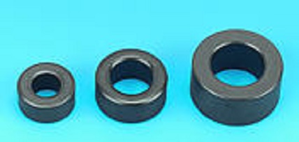
Toroidal cores
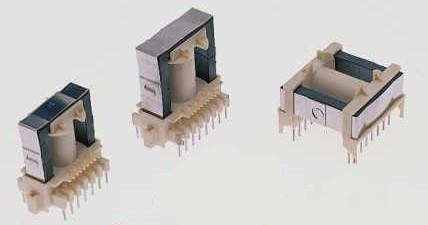
ETD-type cores

Toroid from ITL 100 inductor (Wilco Corp).
(Remove the thick wire before winding!)
These are a few general winding guidelines for all types of cores:
The following are photos of two models of transformers. The left one is a toroidal I wound myself using the core from a big inductor from Wilco Corporation (ITL-501), and the right one is a commercial unit from a US manufacturer (2 x 3:1, 350W). Both worked similarly.
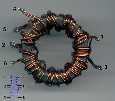
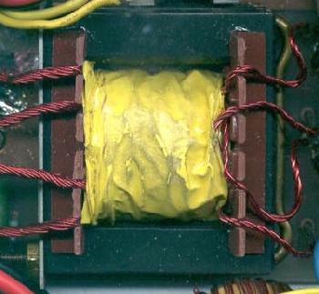
Left - Home Made Transformer. Commercial Transformer - Right
Other remarks
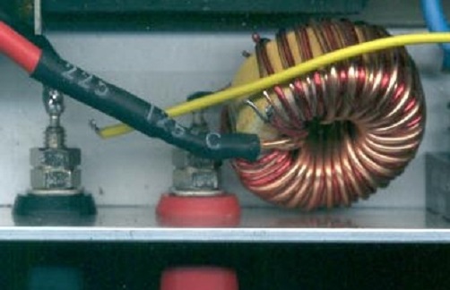
My system's input choke, obtained from an old PC power supply.
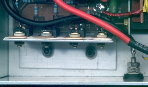
Detail of the MOSFET arrangement
Note the insulation pad (one for all) and the thick supply wires. Individual insulation pads may be used with no loss of performance. Use of a clamping bar will give improved thermal conduction to the heatsink bracket, but do not over tighten, or the bracket will bend. Consider using a bracket of not less than 3mm aluminium for better thermal performance. The bracket must be attached to a heatsink, using thermal compound to minimise the thermal resistance.
This project handles quite large powers, so it is well worth the pain of step-by-step testing before you regret blowing all your work up in a microsecond.
For the tests, use a big 12V to 13.8V power supply, with current limiting if possible and capable of delivering at least 10 to 20 amperes (see project 77). If you don't have that, a PC computer PSU will work (although you won't get more than 80-90W, but it is enough for testing purposes and almost indestructible). Don't connect the SMPS to a car battery the first time you test it (it can be really dangerous!). A 10A fuse in series with the 12V supply is also a good idea. (You don't know to what extent!  )
)
The cables from the supply to the amp should be as short as possible and heavy gauged, to minimise losses. First time I tested the amp I had a 1 volt of difference from one side to the cable to the other in only 1.5 metres: the cable itself was dissipating more than 15W!!!. So, when calculating efficiency, always measure input voltage just at the input of the SMPS to account for this.
The wires from the transformer to the MOSFETs must be as short as possible. Every 10mm of wire adds around 6nH of inductance that's external to the transformer (the exact figure depends on the wire diameter and can only ever be an estimate). This, and transformer leakage inductance, will cause voltage overshoot and ringing on the switching waveform. If at all possible, the MOSFETs should be no more than 20mm from the transformer. Likewise, and wiring (or PCB traces) from the controller to the MOSFET gates must also be as short as possible. As with the MOSFETs to the transformer, try to keep the conductors to no more than 20mm if possible.
When you are completely sure that everything works as expected, you can proceed to connect it to the car electrical wiring (see 'installation procedures' paragraph). First time you will notice an spark due to the sudden charge of the big input capacitor, unless you connect a resistor in series first (very good practice) to allow it charging slowly and then remove it for normal operation.
For your car and own safety, it is VERY IMPORTANT that you pay special attention when installing the power supply (and amplifier) in your car. These are some recommendations that everyone should follow carefully:
The project itself has excellent load regulation, and the rails voltage is almost only determined by the turns ratio, but it has inherently zero line regulation (basically, it 'simply' multiplies the input voltage by the turns ratio), although this is not a problem in a car where the battery voltage remains essentially constant.
If the obtained output voltages are very high and you can't (or don't want to) modify the windings, you can use regulation to lower them a bit. For example, I use a 3:1 transformer that would give about +/-38V without regulation that is unacceptable for my LM3886 stages to be safe, so I have regulated to +/-26V. The MOSFETs will suffer more, however, so regulate the supply only if strictly necessary.
You can install the feedback potentiometer and set it in order to have zero reference voltage to deactivate regulation, or increase its value to regulate to the desired voltage.
NOTE: Regulation will work better with output inductors just between the rectifier diodes and the output capacitors. 10 to 100µH with iron powder core and at least 8A current rating will be adequate. (I don't use them and my supply works reliably, although I never put it to the power limits). You can also improve safety by paralleling more MOSFETs, so the current through them is shared. This also improves efficiency a bit, as the total Rds(on) is reduced.
If you need to power opamps for a crossover, equaliser or preamplifier, you can obtain a symmetrical +/-12V (for example) from the main supply rails, simply with a resistor, zener and capacitor. (see Figure 1 of Project 27). Remember to use 1 or 2W resistors and zener diodes. You can obtain about 25-50 mA from this without problems.
The following material is from ESP - there are some suggestions and additional information, as well as a simplified version of the SMPS.
Although my version of the switcher is simplified, this does not imply that performance is lower than Sergio's original, but is the result of my own experiments and tests. We may be on opposite sides of the planet, but there was considerable collaboration during the development of the supply, and I have built and tested the version shown below.
It has been claimed that MOSFETs are immune from thermal runaway, since they have a positive temperature coefficient for their 'on' resistance. While this may be partially true for a Class-AB power amplifier, it is completely false for a switching supply.
For example, a push pull SMPS using one IRF540 MOSFET a side draws 30A at full load. If we check the data sheet, we find that Rds(on) is 0.044 Ohm (44 millohms) at 25°C, then we know that it will generate ...
P=I² x R = 30² x 0.044 = 900 x 0.044 = 39 W peak (per transistor).
At 50 degrees (not uncommon in a car that has been in the sun for some time), Rds(on) will be about 1.25 times the value at 25°C (this is from the datasheet), or 0.055 ohms. Power dissipation will now be 49W, so the heatsink has to dispose of more heat. We can guarantee that the extra heat will cause the heatsink temperature to rise further, which will increase Rds(on), and that will make the heatsink hotter, and - BANG.
Ensuring that you use parallel devices and a good heatsink will reduce the likelihood of this dramatically. Two MOSFETs sharing the load will dissipate 1/4 the power (each) of a single device, and have a lower thermal resistance to the heatsink as well. The positive temperature coefficient of the MOSFET Rds(on) does ensure that current sharing is effective without the need for balancing resistors (as used in power amplifier output stages).
P=I² x R = 15² x 0.044 = 225 x 0.044 = 9.9 W peak (per transistor) - 19.8 W for both
The power shown per transistor is the peak - actual average power (per device) is half that calculated. The total power dissipated by both transistors (or sets of transistors in the case of paralleled devices) is the full value shown, since when one device is 'on', the other is 'off' and vice versa.
Naturally, the maximum dissipation will only occur at maximum (continuous) amplifier power - the real life requirements are usually somewhat less, however, it is essential that the design is capable of continuous worst case dissipation to ensure an adequate safety margin.
I strongly recommend that you do the calculations yourself, and make sure that you understand the implications.
Normally, one would expect regulation as shown in Figure 1, however, using the feedback input of the controller IC relies rather too heavily on the impedance of the DC supply lines. Normally, output inductors are used (with an additional 'flyback' diode) to provide a pulse width to voltage converter. The majority of commercial systems seem to use a non-regulated converter, so I would consider that this will be quite acceptable in practice. Tests so far have shown that with a load of about 150 Watts, the regulation was almost entirely dependent on the voltage drop in the supply line!
As well as being unregulated, there are a couple of other changes in the circuit. R8 (100 Ohms) is connected between the timing capacitor and discharge pins of the controller IC. This introduces a 'dead time' where both outputs are turned off, and the reason for this is to ensure that the power MOSFET pairs can never be switched on at the same time - should this happen, a very large current will flow (albeit for only a microsecond or less). Since I did not use the extra switching transistors and used higher value gate resistors, the dead time is important.
I also increased the switching frequency. As shown, the internal oscillator runs at approximately 50kHz (my prototype actually runs at 54kHz), where Sergio's original was designed for 35kHz switching. The difference is determined by the resistor on the RT pin of the controller, in my case, 12k.
Regulation will obviously make the circuit much more complicated, and as stated above, my version is unregulated. This will maintain maximum efficiency, and also reduces the dependence on the output filter capacitors - they are effectively fed with almost pure DC from the rectifier at all loads, so storage time is not an issue. Relatively small filter capacitors can be used, and the output will still be quite clean.
Not surprisingly, the turns ratio is very important if regulation is not used. Assume an input voltage of 12V to allow for losses. To obtain +/-24V, the turns ratio is 1:2 - for each turn on the primary, there will be 2 turns on the secondary. This is the same as Sergio's description, and the same rules apply. Unlike a normal mains transformer supplied with a sinewave, the switching waveform is a squarewave, so the peak and RMS values are the same (in other words, there is no 1.414 conversion as would be the case with a mains frequency transformer). The problem with this is that the 12V assumed at full load will be 13.8V under light or normal loading, so the voltage will be higher than expected. Using the same transformer as above (1:2 turns ratio) the no-load output voltage will be 27.6 volts - make sure that you do not exceed the voltage rating of the amplifier!
Figure 9 - Simplified Version of Switching Supply
Since the transformer is relatively easy to wind, it is not a difficult task to dismantle it and add (or remove) secondary turns to get the voltage right. My prototype transformer used 5+5 turns for the primary, and I used 3 strands of 0.8mm winding wire twisted together. There is plenty of room in the recommended core, so it would be easy to use 5 strands instead for lower losses.
Note that in the above (Fig. 9), the heavy leads shown carry substantial current, and must be sized accordingly. I do not recommend PCB traces be used, since the current involved is simply too high. Given that the suggested current density for PCB tracks is 4.0A for a 100 'thou' (0.1" or 2.54 mm) track, then for 30A you need a track 0.75" (19 mm) wide! This is difficult to accommodate on any printed board.
I also eliminated the relay, but at the cost of a small current when the unit is not operating. The SG3525 has a shutdown pin for just this purpose. A signal from the remote head amp will turn on Q1, and remove the shut down signal from the controller. It behaves in exactly the same manner as if power had just been applied, and the unit will become fully operation in about 2 seconds or less. Current drain when turned off will be about 1 to 2mA - considerably less than the clock in the car. Battery discharge will not occur as a result of this very small current, which may be ignored as insignificant. Feel free to use the relay if you prefer, connected as shown in Figure 1.
I recommend that an EDT39 ferrite core is used. These are easy to wind, and are capable of around 350W output. Bear in mind that this represents a considerable battery current at full power, in the order of 30 to 35 Amperes! Heavy transformer windings and supply cables are essential, and the input filter must be capable of withstanding this current without saturating the core.
The former for these cores is rather large, and you may decide to cut the mounting sections off completely. Do remember that the transformer must be mounted somehow though, so I suggest that you have a plan. At this stage, I have only experimented, and do not have a plan.
All of Sergio's previous comments apply to this version, so make sure that you read his material thoroughly. I do not propose to cover the same instructions again, since Sergio has already done an excellent job.
I have done some initial tests, but have not yet connected the bridge and output capacitors. With what was intended to be 12+12 turns on the secondary, I obtained an acceptably clean waveform with some overshoot with the secondary unloaded. Output voltage was about 38V peak, so I obviously had one more turn than I thought I did (input voltage was 14V DC). I cannot stress highly enough that the winding process is critical to the success of your transformer, and you should expect to have a couple of attempts before you get it exactly right. The small number of turns needed makes this much easier than would otherwise be the case.
During my testing, my power supply and load became very warm indeed, but the MOSFETs (I used IRF540s) remained cool, even though they were mounted on a rather small heatsink lying on my workbench. This indicates that the heatsinking requirements are easily achievable, but does not mean that you can be lax with mounting. My transformer also remained cool, with no sign of the core or windings getting even warm. This must be considered a design goal. Even the lead I used to my load became warm, so the power output was very real indeed!
You will need an oscilloscope (or at least access to one) or the project will be very much harder to build and test. A design such as this relies on careful measurements and great care to make certain that it will perform as expected. Attempting this without an oscilloscope is not recommended.
This project has already created far more questions via e-mail than I desired or expected. For everyone who plans on making this supply ... you are essentially on your own. I cannot (and will not) be drawn into lengthy e-mail exchanges if you cannot make the supply work.
That it does work if built as described is certain, that you will be able to achieve the same results is not. If you do not have (or at least have access to) an oscilloscope - don't even think about trying to make the supply, as it will not be possible to ensure that the duty cycle of the controller is exactly 50%, or that there is no severe overshoot or ringing at the output.
Please do not not send me e-mails asking for help. I will simply refer you to this paragraph - I cannot diagnose your problems via mail, and will not even try. It is entirely up to the constructor to determine his/ her abilities before starting.
The construction of any switching supply is fraught with difficulties, risks (including but not limited to electrocution!) and problems that need to be addressed. They are not simple (despite appearances) or easy, and there are a great many things that can go wrong. If you are not 100% confident that you understand the issues involved, please do yourself a favour and build something else instead.
 Main Index
Projects Index
Main Index
Projects Index