
 |
| Elliott Sound Products | Inrush Current Testing/ Project 225 |
 Main Index Main Index  Articles Index Articles Index  Projects Index Projects Index |
While this article is listed primarily as an article, it's 'dual purpose', and it has both construction details (like a project) and the detailed explanations common to an ESP article. Consequently it's listed in both the projects and articles indexes. If anyone wishes to construct it, be aware that it requires considerable experience with mains wiring, and there are some elements that may require some experimentation because of the way it works.
Inrush current is often a big problem, and although there are easy ways to mitigate it (see Project 39) it's a great deal harder to measure it accurately. A web search finds a depressingly large number of clamp-meters and other 'solutions', but methods for activating the mains waveform at a predictable phase angle are few and far between (the most useful are zero-crossing and 90°). A random power-on will certainly show the current measured, but it will almost always be different for every measurement because power-on is random. You need to be able to ensure that the mains connects at the worst time every time, or the measurement is not useful. I tried a number of search terms without success, so it's safe to assume that the specialised zero-crossing and peak switching circuit described here is unique. I have no doubt that there are lab instruments that can do much the same thing, but they will come with lab equipment prices. This is a DIY solution that works very well.
Many years ago I designed a tester that lets me apply power at the zero-crossing point of the mains waveform or at the crest of the waveform (5ms for 50Hz, or 4.17ms for 60Hz). Mine is calibrated for 50Hz since that's the mains frequency in Australia, and I don't need to test at 60Hz. The switching is predictable, with zero-crossing being the worst for transformer and other 'inductive' loads, and peak switching is the worst for switchmode supplies and other 'capacitive' loads. Note that 'capacitive' is in quotes because an SMPS is not electrically capacitive; the capacitor is isolated from the mains by the bridge rectifier. Likewise, 'inductive' is in quotes because the inductance is not a problem, it's core saturation caused as the magnetic field is initiated.
The need for a tester such as the one I built is probably minimal. For test labs and the like, they'll most likely use a programmable supply, capable of generating a sinewave at either 50 or 60Hz, and designed to turn on at the selected phase angle. One I saw was the Kikusui PCR500M AC power supply, but with an estimated cost of over AU$3,000 I doubt there will be a queue of people waiting to buy one. As with any supply that generates the voltage needed, its output current will be limited. The datasheet says it can output a peak of 3 times the rated current - that's only 6.5A at 230V, so high-current tests are not possible. A switched-mains solution may lack the ultimate precision of a dedicated lab supply, but it has the advantage of being able to provide very high current so the measurement is representative of reality.

Please note that the descriptions and calculations presented here are for 230V 50Hz mains. This is the nominal value for Australia and Europe, as well as many other countries. The US and Canada, along with a few other countries, use 120V 60Hz. This is not a problem - the timer can be calibrated for whatever mains frequency is appropriate.
It is likely that testing and/ or background knowledge will be needed before you will be able to make use of the tester described here. In addition, the reader/ prospective builder will have to select parts that are readily available, rather than those suggested. Component suppliers do not always provide information in the same way, and some info included by one supplier is omitted by others. This can make selection a challenge at times.
| WARNING: This article describes circuitry that is directly connected to the AC mains, and contact with any part of the circuit may result in death or serious injury. By reading past this point, you explicitly accept all responsibility for any such death or injury, and hold Elliott Sound Products harmless against litigation or prosecution even if errors or omissions in this warning or the article itself contribute in any way to death or injury. All mains wiring should be performed by suitably qualified persons, and it may be an offence in your country to perform such wiring unless so qualified. Severe penalties may apply. The circuit described is designed for testing at very high instantaneous currents, and these may cause damage to test fixtures or other equipment because tests will usually involve multiple 'worst-case' events. It is the readers' responsibility absolutely to determine the suitability of the tester itself and any/ all other test fixtures. |  |
In many cases, you can estimate the probable 'worst-case' inrush current, but if it's a manufactured product an estimation isn't good enough. In spec sheets, people generally expect measured values rather than estimations, 'educated guesses' or simulations. While these can be just as accurate as a measurement, they are theoretical rather than actual. Mostly it doesn't matter that much, since no-one knows the final location of the product, along with potentially location-specific factors such as the mains impedance. I've measured it at my workbench as ~1Ω, but it can vary, even within the same installation (house, factory, test-lab, etc.).
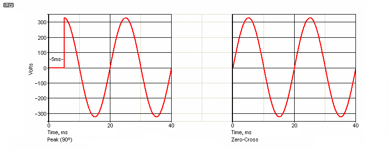
The two switching points of interest are shown above. Switching at the peak of the AC waveform is best for transformer loads, as well as many other inductive loads such as (some) motors, AC powered solenoids/ electromagnets, etc. (see Fig. 1.1). For capacitive loads, switching at the zero-crossing point results in the lowest inrush current. This includes switchmode power supplies, where the capacitance is isolated from the mains by a bridge rectifier, but the capacitor(s) still present a capacitive load at power-on (see Fig. 1.3). Once operating, an SMPS is not a capacitive load, it's non-linear. Failure to understand this is common, and often leads to wildly inaccurate assumptions.
Note: If your mains are at 60Hz, the timing for the waveform peak is 4.167ms, not 5ms as shown above. The tester is designed to let you select the exact timing needed, by altering the threshold voltage of an opamp wired as a comparator.
The tester is designed to let you switch between peak and zero-crossing, so the worst-case condition for a load can be determined. When equipment is used normally (with turn-on at a random point in the AC waveform), the peak inrush current can never exceed the worst-case condition. A simple power switch is effectively random, as the user cannot synchronise the moment of turn-on to any point on the AC waveform other than by accident.
When performing inrush current tests, you ideally should know the expected range in advance. The estimate doesn't need to be too precise, but without it you may spend a silly amount of time trying to make sense of the measurement data you get. A rough idea of the series resistance will get you a reasonable estimate of the worst possible inrush current. For example, a transformer with a primary resistance of 10Ω cannot draw more than 23A from 230V mains (based on the RMS value of the AC waveform). Switchmode power supplies often have minimal series resistance before the main filter caps, and the current can be much higher than you expect. Even a 220nF X2 capacitor can draw over 100A, but it lasts for such a short time (typically less than 2μs) that they don't cause a problem for switching systems.
The inrush current is usually specified as peak, and converting it to an RMS measurement is (IMO) inappropriate for a transient event. Often, you can get a fair idea by simple calculation, depending on the nature of the DUT. Switchmode power supplies are fairly easy if you have access to the internals (with power off of course). If you measure the series resistance of all parts between the mains input and the filter capacitor(s), that is the limiting resistance when power is applied at the crest (peak) of the mains waveform. The diode bridge makes this a little harder unless you know the dynamic resistance of the diodes, but you can just use an educated guess of around 1Ω for most. If you measure a total resistance of (say) 5Ω, add 2Ω for the diodes (two are in circuit for each polarity of the mains waveform). The ESR of the input capacitor can be added, and this will be somewhere between 100mΩ to perhaps 2Ω, depending on value and voltage rating.
Since I use 230V, 50Hz, I know that the peak of the AC mains waveform is ~325V at 5ms after the zero-crossing. We calculated a resistance of 7Ω, so the worst case peak current is about 46A. Should the AC be turned on at any other phase angle, the inrush current will be lower than the calculated value. The value calculated this way will always be somewhat pessimistic, but you need to consider that the mains voltage is not a fixed value. The tolerance is generally ±10%, but it can (and does) vary by more on occasion.
With most SMPS there's another influence as well. There will invariably be an X2 capacitor in parallel with the mains, and generally another following an input common-mode inductor (choke). Even in circuits that have an inbuilt inrush limiter, the input filter is not subject to any such limitation, so if the mains is turned on at the peak of the AC waveform, the current through the X2 caps is limited only by the mains impedance and the ESR of the X2 caps. This is usually very low, so the input current is very high, but only for a very brief period. This is sometimes included in any inrush current specification, but in reality it's immaterial because the current peak is so brief.
An 'ideal' 220nF X2 capacitor will theoretically draw as much as 300A when power is applied at the mains peak, but the duration is less than 1µs. This is real, but of no real consequence because it's so brief. The only limitation is the mains impedance and any series inductance. As little as 1µH of inductance will reduce the theoretical peak current to around 110A, and spreads the current pulse to about 1.5µs. This is still immaterial, as no fuse or circuit breaker can possibly react to such a short current pulse.
The process is less well defined for mains transformers. Ideally, they would be turned on at the peak of the AC waveform, as this minimises the inrush current (quite the opposite of what many people believe). Unfortunately, the transformer is almost always followed by a bridge rectifier and filter capacitor(s), and to get minimum capacitive inrush current zero-crossing is better. These two are in opposition to each other, so neither is optimal.
In theory, the worst-case transformer (saturation) inrush current is limited only by the primary resistance of the transformer. However, it's impossible to get this under any realistic test conditions, and you can get a rough idea of the maximum by dividing the AC RMS voltage by the primary resistance. For a transformer with a 10Ω primary, you'll probably measure a maximum inrush current of up to 23A or so.
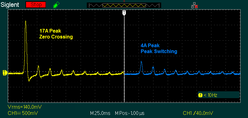
Figure 1 has two captures combined into one, and shows the inrush current waveform captured when power is applied at both the mains zero crossing point and at the peak. The transformer is a single phase, 200VA E-I type, with a primary resistance of 10.5 Ohms. The scope scale is 5A/division. Absolute worst case current for a transformer is simply the peak value of the mains voltage (325V), divided by the circuit resistance. This includes the transformer winding, cables, switch resistance, and the effective resistance of the mains feed. The latter is usually less than 1Ω, and allowing an extra Ohm for other wiring, this transformer could conceivably draw a peak of about 28A. My inrush tester also has some residual resistance, primarily due to the TRIAC that's used for switching. Although it's bypassed with a relay, there is a time delay before the relay contacts close and this reduces the measured inrush current slightly. Peak switching quite obviously reduces the inrush current dramatically, from a measured 19A down to 4A.
A toroidal transformer will be much worse than the one shown. They saturate much harder than E-I transformers, and usually have a lower primary resistance for the same ratings.
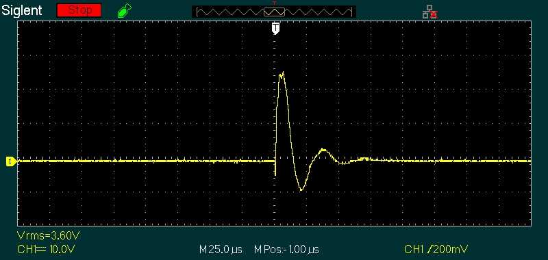
For reference, Fig. 1.2 shows a 3.3µF cap switched on at 90° (325V peak). Look carefully at the scale - 10V/division. The current transformer's output was 100mV/A, so with 23V peak shown on the scope trace, that makes the current 230A!. That means there's a total series resistance (mains, test unit and leads, etc.) of about 1.4Ω, which is in line with my expectations. The pulse lasts for only 500ns (give or take) and the 'wobbles' after it are a direct result of parasitic inductance. A very rough estimate is about 11nH of inductance, which is actually less than I would have guessed. This isn't important of course, but it is slightly interesting. Note that I recommend a 10Ω burden, giving 10mV/A.
Of greatest interest is the peak current. The current transformer I used is an AC1005, which is sold as a 5A CT, but I already knew it extended well past that. I didn't expect it to give a reading with 230A though - that is rather extraordinary performance from a cheap 5A CT. The measurement is almost certainly fairly accurate, although the current transformer will saturate at this current. The peak current can be estimated, given the known mains impedance at my workshop and the internal resistance of the tester and its mains leads. The capacitor used was designed for pulse operation, so has minimal internal resistance.
The stress placed on a bridge rectifier when subjected to such high current (even briefly) is considerable. Given the current measured, you can imagine how bad it can be with a switchmode power supply. The very high inrush current applies for both 'standard' (no PFC) and supplies with active PFC. These almost always use a NTC thermistor to limit the peak current. While effective, there are some serious compromises needed in most cases. For more information, see Inrush Current Mitigation, which discusses the techniques and limitations.
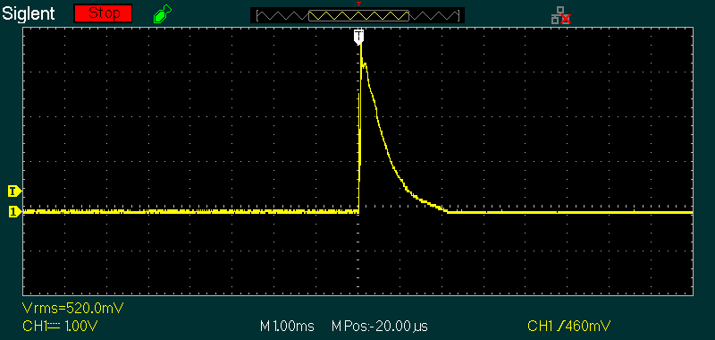
Fig. 1.3 shows a capture for a small SMPS. It's only rated for 60W (24V at 2.5A), and it has active PFC. There's a narrow spike that extends to 44A (partly obscured by the trigger marker), which is due to the input EMI filter cap (330nF X2). The main PFC input capacitor draws 32A peak. This is one of several captures, and the result was identical each time. Mains was applied at the peak of the AC waveform (325V nominal), indicating that the total series resistance in the SMPS is around 9Ω (the mains impedance is roughly 1Ω at my test bench). Repeatability is very important for tests, and the consistent results I obtained are what should be expected. If the supply is turned on at the zero-crossing, the peak current is only 6.2A (again, absolutely repeatable, but not shown).
A simulation of the circuit using an 82µF main filter cap gave almost identical results to those I measured. Given that a simulator is capable of accuracy unmatched by any test equipment this is a good result. Importantly, theory and practice are in agreement. This is always a requirement when performing tests - if you get wildly different results for a simulation or estimation and the measurement, something is wrong.
A measurement system relies on a defined turn-on behaviour. While it is possible to detect the peak of the mains waveform, using it as a reference is imprecise and it's not practical. The zero-crossing point (where the mains voltage reverses polarity) is easy to detect with acceptable accuracy, and is the method used. Zero-voltage detectors (ZCDs) are common in many phase-controlled devices, particularly dimmers and other circuits where AC phase control is required. This circuit is no different.
There are only two possibilities of any great interest; turn-on at zero or 90°, where 90° takes the turn-on point to the peak of the waveform. Zero-voltage switching is the optimum for SMPS and other capacitive loads, as the maximum rate of change is that created by the mains voltage itself. A 230V 50Hz waveform has a maximum rate-of-change (aka slew rate, ΔV/Δt or dV/dt) of 102,102V/s (0.1V/µs). A 120V 60Hz sinewave has a maximum ΔV/Δt of 63,968V/s (0.06V/µs). When power is applied at the peak, the ΔV/Δt depends on the TRIAC used, but will typically be several hundred volts per microsecond. The maximum slew rate of a sinewave is at the zero-crossing, and is calculated by ...
ΔV/Δt = 2π × f × VPeak
At least in theory, if the mains is connected at the zero-crossing, the inrush current into any capacitive load (including rectifier-capacitor loads) is mitigated. However, this isn't always as easy as it sounds. If a relay is used, there will be contact bounce when it operates. This will create multiple 'events'. A TRIAC can be used, but it will be unable to turn on with zero volts across it, as no current can be drawn. TRIACs are also unsuitable for most 'electronic' loads, because there is inevitably a 'dead' period. The solution I adopted was to use a TRIAC, along with a relay in parallel. The TRIAC triggers immediately (or when the voltage is more than ±25V or so). Near the zero-crossing point, the voltage across the TRIAC reaches 50V within 500µs as indicated by the ΔV/Δt formula above. The relay contacts will close after about 2-10ms (relay dependent), bypassing the TRIAC to prevent misbehaviour with electronic loads. It's important to ensure that the relay operate time is as fast as possible. If the relay is too slow, there may be a momentary 'disconnect' if the TRIAC turns off due to a difficult load. I used a perfectly ordinary 12V relay and have never seen a 'problem' waveform.
To trigger at a particular point on a waveform you need a reference. It's possible to detect the peak, but it's poorly defined and subject to small voltage variations all the time. Almost all processes that need a specific reference for any AC waveform use a zero-crossing detector (see Zero Crossing Detectors and Comparators. Although there is always some 'dead-time' around the zero-crossing point, as long as it's predictable it doesn't matter.
The next part of the system is a timer. The zero-crossing detector discharges the timing capacitor when it goes high, and the timer starts when the voltage falls low again. The timer is set for just under 5ms to obtain peak switching (corresponding to the peak of a 50Hz waveform), or 10ms for zero-crossing. The timing needs to be set with a suitable monitoring system (a small isolation transformer and an oscilloscope), and carefully adjusted to get as close as possible to zero and peak. For reasons that escape me now, my tester uses a PIC rather than an analogue timer. It does reduce the parts count a little, but it also means that the PIC has to be programmed for the proper delay. (Yes, I know that I could have used an ADC input and a trimpot, but if I did that the parts count advantage all but disappears.)
The idea proposed here is to use an analogue system, as it's then possible for anyone to build it without having to devise the program for a PIC. The circuit consists of a zero-crossing detector, timer, and a switch that controls both a TRIAC and a relay. The current waveform is obtained using a current transformer. I know that this arrangement works, as evidenced by the waveform captures shown in Fig. 1. It also requires a power supply, and the innards of a switchmode plug-pack (aka 'wall wart') is by far the easiest way to provide power with the minimum of fuss. As noted in the introduction, experience with mains wiring is an absolute requirement.
Note: Do not use an external plug-pack/ wall-wart with a DC connector to power this circuit. Even though the supply and low-voltage circuitry is isolated from the mains, it's a particularly (potentially) hazardous piece of test gear, and maintaining total isolation between the mains, control circuit and current transformer output is (IMO) an absolute requirement.
There are a number of zero-crossing detectors shown in the ESP application note linked above, but the one selected is the simplest arrangement that works well. It uses an optocoupler to detect when the AC voltage is within about ±5V of zero, which gives a pulse just under 1ms wide, centred on the mains voltage passing through zero. Any small timing error is easily dealt with by calibrating the timer. Since the TRIAC can't turn on until it has at least a few volts across it (depending on the load), it's not possible to turn on at exactly zero, but the error is small. Ideally, the relay should be selected to ensure its contacts close in less than 10ms.
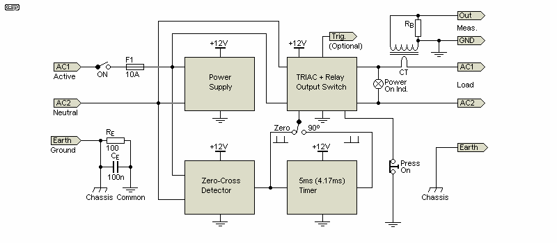
The block diagram shows the sections used. There are three main blocks, excluding the power supply. The zero-crossing detector (ZCD) is powered directly from the mains, using an optoisolator for safety. The output pulses trigger the timer, which produces a high output 5ms (or 4.17ms) after the zero-crossing. The output switch uses a TRIAC and a relay connected in parallel. Monitoring is provided by a current transformer, with a pair of terminals for an oscilloscope. All current transformers require a 'burden' resistance (usually 100Ω for small ones) indicated as RB on the drawing.
RE and CE are used to ensure that the electronics and accessible terminals aren't floating with respect to the mains safety earth. This prevents the likelihood of getting 'tingles' if you touch the CT output terminals or the optional trigger output, and the resistance is high enough to prevent ground loops that may induce hum into the measurement. The small switchmode supply suggested will have a 'floating' common output voltage of up to half the mains voltage, and the network prevents this.
For zero-voltage switching, the TRIAC and relay are turned on with the first zero-crossing pulse detected after the 'on' button is pressed. The 5ms (or 4.17ms for 60Hz) delay timer provides an output pulse at its output of about 250µs wide. This delayed pulse is used for 90° switching. The first pulse to arrive from either the zero-crossing detector or the timer (after the 'operate' switch is pressed) activates the TRIAC and relay. I suggest a momentary normally closed pushbutton, because there's no reason to keep the external device turned on once you've captured the inrush waveform. Selection is simply a switch to connect the impulse desired. There is a very good reason for having the output indicator LED powered directly from the switched output. This is discussed in detail below.
If you think you need it for some obscure reason, VR1 can be installed as a front-panel control, allowing you to set the phase angle to something other than the default 90°. If you were making a dimmer or power controller this might be seen as 'useful', but in this application it's not. The two phase angles needed for any inrush test are 0° (zero-crossing) and 90° (AC peak voltage). Other phase angles will give a result partway between the two, but that's rarely necessary or desirable. The circuit is designed to apply power only when the 'Operate' button is pressed, and it turns off again when the button is released.

The heart of the system is the ZCD, as this determines the timing of the output switch. An optocoupler (4N25, 4N28, LTV817, etc.) has its LED powered from the mains, via a resistor string and a bridge rectifier. The output is buffered by an emitter-follower (Q1) so it can provide enough current for the timer and latch circuits. See Fig. 2.3 or 2.4 for more accurate ZCDs, which will work better with optocouplers having a low CTR. Please note that the two brown terminals (active/ live) are joined, as are the two blue (neutral) terminals.
Note: R15 is shown as 10Ω and I've verified that the AC-1005 CT can handle up to 70A without saturation with that burden resistance. If you need to measure higher current, R15 should be reduced further (to 1Ω), and the output will be 1mV/A. Alternatively (and preferably), use a CT designed for higher current. I've tested to over 150A (the maximum I can achieve as a continuous current using Project 207 - High Current AC Source with a 10Ω burden (R15) with only minor signs of saturation. I'd expect linear output up to at least 200A, and probably more. R14 can be switched between 100Ω and 10Ω if you need to measure very high current.
The timer capacitor (C1) is shown as 1µF, and it must be a film cap. Don't use a multilayer ceramic or electrolytic cap, as they are not stable over time and temperature. Test equipment must be reliable and predictable, but the wrong type of capacitor will be neither. The exact value isn't critical, as VR1 has plenty of range to account for tolerance.
The first comparator (U2A) is the timer, which runs continuously and is reset by the zero-crossing signal. The second comparator (U2B) is configured as a latch. When the output switch is in the 'off' (not pressed) position, the latch is inhibited (zero volts output). When the switch is opened the first impulse to arrive turns on the latch, the relay and TRIAC. The impulse can be selected for 'zero' or '90°' as required with Sw1. The optional scope trigger output is derived from the output of the latch. Power is only supplied to the DUT while the 'Operate' button remains pressed. Note that you cannot substitute 'any old' opamp for the LM358. It was specifically selected because its outputs can get down to (close to) zero volts, so it can switch the transistors with the minimum of parts. You can use a dual comparator (e.g. LM393), but then you must add resistors from the outputs to +12V. A value of 1k will be fine.
The output from the ZCD and timer are positive-going pulses, at a 100Hz (or 120Hz) repetition rate. Because the timer is adjusted to 5ms (or 4.17ms), this corresponds to the AC waveform's peak voltage, which may be positive or negative. While it's not difficult to set up the circuit so that it will always trigger on (say) positive peaks or an initial positive half-cycle, this was considered to be unnecessary. In 'real life', switching phase angle and polarity are random, so at least the polarity is allowed to be random in this design. The trigger output will ensure that the scope always triggers at the instant the mains is applied.
The suggested TRIAC is a BTA41, rated for 40A continuous or 400A peak (non-repetitive). You could use a 'lesser' TRIAC such as a BT139, but they are only rated for a peak current of 140A. As seen above (Fig. 1.2) this may be limiting. The TRIAC is turned on using an MOC3021 (~10mA trigger current). Any of the MOC302x series photo-TRIACs can be used, but you may need to adjust the LED current. These devices have been with us for a very long time, and are available from most suppliers. All wiring (including Veroboard traces if applicable) has to be capable of withstanding a peak current of at least 400A without vaporising.
The zero-crossing detector's optocoupler isn't critical, but some have a rather poor CTR. If you're prepared to modify the circuit a little, you can use whatever you have available. The CTR is simply the ratio of LED current to transistor current, so a CTR of 1 (or 100%) means 1mA through the LED will cause 1mA collector current. The relay shorts out the TRIAC, and they are activated at the same time. Most relays will close within around 10ms or so, and while I didn't test mine it's been used on a wide variety of products and hasn't missed a beat.

Note: Do not use a zero-crossing TRIAC driver (e.g. MOC303x or MOC306x series). The device used must be classified specifically as 'random phase' or 'non-zero crossing'. Zero-crossing optocouplers will not work in this circuit, because they cannot be triggered at the peak of the waveform. This should be obvious, but it's also easily missed.
One thing that's (surprisingly) important is that the 'Mains On' indicator is powered directly from the switched mains output. During some tests, I discovered that the TRIAC can 'self-trigger', so the output is still on, even after the relay and MOC are no longer powered. Capacitive loads are the most troublesome in this respect, and the 3.3µF capacitor I tested (see Fig. 1.2) would cause the TRIAC to re-trigger itself reliably. Had the indicator been powered from the DC control signal, there would have been no indication that something was amiss. It's a minor point, but IMO a fairly important one. Some transformers will also cause re-triggering, although most don't.
You may wonder why I specified 1N4148 small-signal diodes for what look like mains rectifiers. Because they come after the resistors (series strings to ensure there's no voltage breakdown), the maximum voltage across them is only a couple of volts, as determined by the LED forward voltage. These resistors should be ½W. For 120V operation, simply omit one resistor from each leg of the network. This reduces the total resistance from 40k to 20k.
One thing you'll almost certainly have to test thoroughly is the ZCD. With the values shown, peak LED current is 8.1mA. There's a balancing act with a simple ZCD, because we want the pulse to be as narrow as possible, but the LED current has to be as low as we can get, consistent with reliable operation. The optocoupler I used is an LTV-817C, which has a claimed CTR of 200-400%. This is much higher than the more common 4N25/8 which has a CTR of 1 (100%) at 10mA LED current.

The ZCD shown above is adapted from the ESP app. note AN005 - Zero Crossing Detectors and Comparators. It's a little more complex, but it does have the advantage (at least in theory) of a very narrow output pulse (less than 500µs). It's also more dependable than the simple version shown in Fig. 2.2, and is less likely to need any adjustment to get it right. Because the optocoupler you use will be different from the ones I've used, using a circuit that doesn't rely on a high CTR has many advantages. Having bench-tested this ZCD, I found that the minimum pulse width is about 650µs - not quite as good as a simulation indicates, but better than the simple version.
It also draws far less current from the mains, so you can use high-value input resistors. The 200k resistors shown will be 2 x 100k in series. For 120V operation, the total resistance needed is 100k on each 'leg', so omit 2 x 100k resistors. If you need a higher LED current (unlikely but possible), reduce the value of R4. As shown the LED current is about 9mA, and if R4 is reduced to 100Ω, the peak LED current is 12mA. The output is taken from the emitter of the optocoupler because the optocoupler is normally off, and it's turned on when the mains voltage passes through zero. This has the advantage of keeping the average LED current low, ensuring a long life.
It is possible to make a ZCD with a pulse-width less than 150µs, using a Schmitt trigger logic IC. It can be powered directly from the mains (no additional supply needed), but it's overkill for this application. The timing for the TRIAC for zero-cross switching is immaterial because it's the MOC and TRIAC that determine the switching point. For 90° switching, the timing is adjustable, so an ultra-high precision ZCD serves no purpose there either. This is definitely a case of not letting 'perfect' be the enemy of 'good'. The ZCD shown in Fig. 2.2 is quite sufficient.
Note: For what it's worth, my unit uses a BTU2540 TRIAC (long obsolete, but I have a bag full of them). This device is rated for 25A continuous and 250A peak, so it was severely overloaded when I did the 3.3µF capacitor test. It has managed to survive every abuse I've thrown at it in the 12 years or since it was built, so using a BT139 TRIAC is likely to be quite alright for the majority of tests. I leave it to the reader to decide if a peak current of 400A (BTA41 TRIAC) is really necessary. The BTU2540 finally blew up when subjected to a 1.5kVA toroidal transformer (a total series resistance of less than 2Ω).
The supply voltage must be regulated, as the timer relies on a consistent voltage for the comparator (U1A). The simplest is to 'cannibalise' a plug-pack/ 'wall wart' supply and extract the PCB from it. This must be mounted securely within the enclosure. I leave it to the constructor to work out the details, but it's not at all difficult. The current needed is minimal, and will be less than 100mA under all conditions. Test the supply to make sure that it maintains regulation at low current, as some are fairly poor with less than 12mA. That's roughly what you'll get when the tester is 'idle' (waiting to be activated). Once the relay is activated the current will be about 50mA.
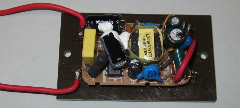
Using a supply such as that shown means that most of your circuit testing can be done safely, and you don't need switches rated for the mains voltage. Make sure that the supply board is securely mounted, and that any wiring below the acrylic (or other plastic) is protected. This style of mounting is very secure if done properly, but there are live terminals that are accessible. If possible, use an enclosure to house the PCB, to ensure that accidental contact with the mains is not possible.
Be very careful when running initial tests, because the ZCD is powered from the mains. Insulation between the control circuit and the mains switching devices is critical. I suggest the that mains side of the ZCD be assembled as a unit, and enclosed in heatshrink. Do the same for the output 'on' LED. Note that the LED leads are still regarded as being at a 'hazardous voltage', and contact with them may be fatal.
Note that the mains earth/ ground should not be directly connected to the common of the circuit. This allows you to use an oscilloscope without creating a ground loop which may cause false triggering in some cases. If the idea of 'floating' electronics doesn't appeal to you, you can use a 10Ω resistor between the mains/ chassis earth and the common. One side of the current transformer must be connected to the circuit common so there's a reference for the trigger output (if included).
The only thing needed for setup is to change the resistors feeding the optocoupler and 'Power On' LED. These circuits both use 4 x 10k resistors for 230V operation, or 2 x 10k for 120V. No other changes are needed, as the power supply will have been selected to suit the mains voltage applicable for where you live. The timer has plenty of adjustment range and will work with either 50Hz or 60Hz without changing any parts.
For calibration, you need a dual-trace oscilloscope. One channel monitors the zero-crossing pulse ('Zero' output to the switch) and should be set as the trigger channel. The second channel is used to monitor the output of the differentiator (the junction of C3 and R6). Adjust VR1 until the delay is exactly 5ms for 50Hz or 4.17ms for 60Hz. The 'Operate' switch should be pressed ('on') for this step). If the switch is closed (output off) the differentiator output is greatly reduced, but it should still be visible on the scope.
Make sure that you verify that the power supply's regulation is within about ±20mV or so over the full likely mains voltage range, as the voltage determines the current into C1 and therefore affects the timing. If the supply isn't good enough, use a 10V 1W zener diode to clamp the voltage at the 'top' of R1. You'll need a resistor between +12V and R1 of about 100Ω to get 20mA zener current. R1 will need to be reduced to 47k. This isn't shown in Fig. 2.2 but it's easily added if needs be. Most small SMPS are fairly good, but you can add the zener if you choose.

The simulation capture shows the voltages and timing you're looking for. Once this is set the tester will trigger the SCR and relay at the appropriate time. This can be verified using a small transformer at the output, and monitoring the secondary voltage. Because the mains voltage waveform is always subjected to some distortion (usually 'flat-topped') there is a little leeway for the 90° setting, but if necessary you can 'fine tune' VR1 to get the trigger point as close as possible to the actual (as opposed to theoretical) peak voltage. In real terms it makes little difference, but it's worth getting it to be as accurate as possible.
The latch will be turned on about 150µs early with the zero-crossing signal, because it's not a particularly narrow pulse. While this can be improved by using the Fig. 2.3 ZCD circuit, it makes no difference to the measurement. The zero-crossing turn-on point is controlled by the MOC3021 and the TRIAC, and these can't be changed. I originally experimented with the idea of using just the relay, with the timing adjusted to suit. Relay contact bounce caused far more problems than the TRIAC, so that approach was abandoned.
Because it's self-contained, this tester is very easy to use. The DUT is connected to the output socket (typically a standard mains outlet), ensure that the 'Operate' switch is off (if you use a toggle switch), and select the desired phase angle. Connect an oscilloscope to the 'Meas.' (measure) and GND terminals, and set it for single sweep. You'll need to set the scope's trigger appropriately to capture the waveform. If used, connect the 'Trig' output to the scope's trigger input and set the trigger input as needed (rising edge). Note that a digital scope is required so the trace will be displayed after it's been captured. You will almost always have to run some preliminary tests first so the scope is set to capture the entire start-up event. If you're testing a complete power supply ('linear' or SMPS), remember to either use a load or discharge the filter caps before each measurement (a load is much easier). You need to test with no residual charge in the filter caps, or the test results will not be accurate.
With the suggested current transformer, the output is 10mV/A, so a 100mV peak signal means a current of 10A. Ideally, you'll capture a number of 'events' to ensure that the waveform you see is representative and consistent. It is possible (although actually quite difficult to do even if you try) to switch the output 'on' part-way through a trigger pulse, and this may give an inaccurate reading. Normally, if the circuit doesn't trigger on the first impulse received, it will trigger on the next - the latch ensures that this occurs. The output is normally unambiguous, and the waveforms shown above were easily reproduced many times. There will often be minor variations in the peak current displayed, usually as a result of not waiting long enough before repeating the test (especially important with switchmode power supply testing).
Because the circuit operates with random phase, if you don't include the 'Trig' output you'll find that not all activations are shown on the scope, depending on its trigger settings. For example, if the scope trigger is set for positive-going pulses of greater than zero, you may not see negative-going activations. This is solved by using the optional 'Trig' (trigger) output. This is a positive-going signal that's synchronised to the mains switching point.
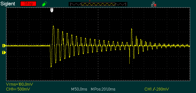
A test example is shown above. The power supply is a 1kVA transformer with 22,000µF filter caps for each rail (±90V) and a 1.2Ω primary resistance. Without an inrush limiter it will trip the circuit breaker for my workbench nearly every time, but it's normally only powered on via a Variac so the voltage is ramped up and there's no stress. The test waveform shown was obtained with zero-voltage switching, and only reached a bit under 10A peak. This is reduced to 7.5A peak with peak switching at 90° (also with 30Ω inrush limiting). The current is a bit less than the theoretical maximum due to added resistance in the test fixture I used. The current jumps up again after the bypass operates at ~350ms, but it only increases to about 6.5A and falls quickly after that.
This demonstrates both the tester and the inrush limiter in action with a real power supply, something you don't normally see at this level of detail. The effectiveness of both the tester and inrush limiter are quite obvious. Without inrush limiting, the power supply can draw over 100A when powered on, and the current 'surge' lasts long enough to trip my circuit breaker.
Unlike AC, DC inrush tests are easy. DC is continuous, and you can apply power whenever you like to measure the inrush. Consequently, there is no specific circuitry needed, just a switch and a means of measuring/ monitoring the peak current. You can't use a current transformer to measure steady-state DC because they only work with AC, although you can use one to measure inrush. I've tested this, and the results are pretty accurate.
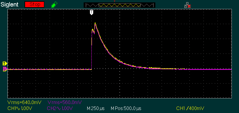
Lest you think I must be mistaken, the capture shows DC inrush measured using a 100mΩ resistor (yellow) and a current transformer (violet). Neither was calibrated and there's a small error, but even so it's minimal and not worthy of much comment. The capacitor used was 220µF 400V, charged via a switch from a 50V supply. The 'wobble' at the beginning of the trace is due to contact bounce in the switch. Note that the RMS voltages shown are not accurate, and should be ignored.
The only resistance used was in the test leads and 100mΩ resistor. Both traces show 100mV/A, so with a peak voltage of 3V, the peak current is 30A. That implies an effective series resistance of 1.67Ω. This was set up as a quick test, so I made no real effort to minimise resistance. However, it still shows the trend very clearly, and all switched DC circuits with a capacitor following the switch will do the same. Without external resistance (or peak current limiting), the only limitation is the ESR of the capacitor.
The benefit of using a current transformer is that there's no additional series resistance. It works with DC, but only to measure the inrush current, and any current drawn by the load is only registered if it changes suddenly. I suspect that few readers would have thought that this could work, but Fig. 6.1 shows that it displays the current change (Δi/Δt) very well indeed. If a larger capacitor were used with minimal series resistance, it's easy to see that the peak current can exceed 100A. DC inrush is a very real phenomenon, and regularly catches people unaware. It should come as no surprise that a simulation shows nearly identical results (but without the contact bounce).
In some cases it may be inconvenient to have to use an oscilloscope to measure the peak inrush. If this is the case, a sample and hold detector can be used, with a multimeter to measure the peak. Since we only have a single supply available, this is made harder than it would be otherwise, but a good reading is still possible within around 5 seconds after the 'event', while still using a budget dual opamp. There are limitations of course, but it should be easy enough to get a reading within 2% or so. Be aware that the circuit shown is not super-fast, so very short transient impulses may not be captured accurately. The output is only 10mV/A, so it won't capture and hold low current accurately.
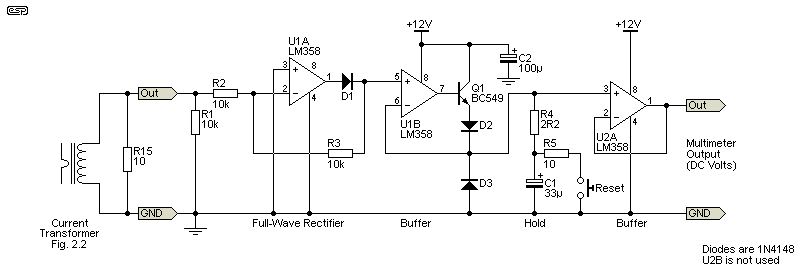
It's probably easy to look at the circuit and think "that can't possibly work", but it does. See the Precision Rectifiers application note, Fig 8. It's not much use with very low current, and with the suggested current transformer and 10Ω burden resistor (R15, Fig 2.2) the lower limit is around 10A (100mV peak output). Operation up to 900mV peak (90A) is possible with fairly good accuracy. The biggest issue is the LM358 opamp, which has a significant input current. This causes the hold capacitor (C1) to charge, so the voltage increases with time. If R15 is 10Ω, the minimum current is about 100A (1V = 100A). To improve low-level accuracy, R15 can be increased to 100Ω - you can use a switch to change the range.
Readings have to be taken fairly quickly (ideally within about 5 seconds) or the measured result may be incorrect. Within the 5 second 'window', you should get a reading that's well within 1%. The worst-case input current for an LM358 is 100nA, which will cause C1 to charge at a rate of 10mV/s. For the 'typical' value (45nA), the cap will charge (at least in theory) at a rate of 4.5mV/s. However, this is not a linear relationship, and it's hard to compensate accurately. However, a bench test showed that it's not likely to be an issue, largely due to the much larger than 'typical' hold capacitor.
By using a much larger cap than normal, the 'voltage creep' is minimised. To use this circuit, press the 'Reset' button, then trigger the inrush tester. The peak voltage will be held for long enough for you to read it, and the output is 10mV/A. If you read 3.5V on your multimeter, the peak current was 35A. Don't delay between the reset and operate processes, as C1 will start to charge as soon as the Reset button is released. If you're really lucky, the input current from the LM358 will match the leakage of the capacitor, but I think that's probably too much to ask for. 
D3 also has some (temperature dependent) leakage, and that helps to prevent voltage drift. Ideally, U2A would be a JFET input opamp (e.g. TL071), but they won't work properly in this role with a single supply. You can use a CMOS opamp (e.g. TLC277) which will maintain the peak measurement for a very long time, but it's an added part that probably isn't worth the extra trouble. If you were to use a TLC277 or similar, D3 should be removed.
I tested an LM358 as a buffer with a 33µF 25V cap, and it started at 6.4mV (the output can't get exactly to ground). It took 42 seconds for the voltage to rise to 50mV (1.2mV/s), much better than I expected. With the cap charged to 5V (equivalent to 50A), the voltage remained quite stable, so capacitor leakage and bias current were presumably balanced. Provided the measurement is taken fairly quickly, you can expect it to have more than acceptable accuracy. A scope is still the best of course, as it lets you see just how the inrush current progresses with time.

Something you'll see advertised is a clamp-meter, specifically for measuring current without having to break the wire. Many have a 'peak hold' function, which is alleged to let you measure inrush current. I have one, and it can't - despite the claims. Yes, it has 'Hold', 'Min' and 'Max' functions, but unless it samples at the exact moment the inrush surge occurs, it can't capture it. Try as I might, I couldn't get that to happen. I tested it with the same capacitor used for the Fig 6.1 capture, and it failed every time. My scope assured me that the full 30A was delivered, but the highest reading I obtained was 1.8A, well shy of reality. These meters will measure inrush for long-duration events (a motor starting for example), but they cannot (and do not) handle short-duration events at all.
Normally, this would be published as a project, because it includes a full schematic and lots of construction info. However, because it's so specialised I decided that it was more appropriate for it to be presented as both a project and an article. I don't expect that many people will actually want to build one of these testers, because it's not needed for any 'normal' hobbyist testing. However, I may be mistaken, and as it's not particularly expensive to build, it is educational to see just how much current some products draw when switched on. Whether this justifies construction or not is up to the reader.
It's also ideal for verifying that a soft-start circuit (aka inrush limiter) works properly, and has an acceptable delay. I've used mine both to test commercial products (mainly lighting) and to verify that the Project 39 soft-start circuit works properly with a variety of transformers and filter capacitors. I know that I can easily estimate (and/ or simulate) the results fairly easily, but being able to prove it on the workbench is always useful. It's also been used to show scope captures of transformer inrush in other articles and projects.
Without a tester like this, it's very difficult to capture the worst case inrush current. Most electronics are turned on with a manual switch, which is random. There are also connections and disconnections caused by contact bounce (which occurs with all mechanical switches, including relays). The TRIAC ensure that there is no 'bounce', because it turns on cleanly. If the relay is a bit slow to pick up it's theoretically possible for the TRIAC to cease conduction, but I've not seen any evidence of that happening when using my unit. The 5A current transformer may seem like it's a serious limitation, but as shown above I had no difficulty measuring 230A with a 3.3µF capacitor, and every measurement I've taken was well within expectations.
There's a likelihood that some people will be mislead by claims that clamp-meters can measure inrush. If they do manage to get a reading, it's at a random phase angle, and may underestimate the reading very badly. They do not capture the peak value accurately unless it occurs at the instant the meter takes a sample, something that's highly unlikely in most cases. The sample & hold circuit shown in Fig. 7.1 may come in handy, but an oscilloscope is needed to get a meaningful reading. Inrush testing isn't easy, but most of the time it's not essential either.
There are no references. Information on how to build your own inrush tester is virtually non-existent (I found nothing at all), and my tester was designed using basic principles. Although the original unit I built uses a PIC, the version shown here uses discrete parts throughout. The PIC I originally used required a delay loop determined by experiment, as it had an inherent delay that skewed the results. The discrete version uses a simple timer that can be set easily. There are a few references throughout this article, all from the ESP website.
 Main Index Main Index  Articles Index Articles Index  Projects Index Projects Index |